Table of Contents
Advertisement
Available languages
Available languages
Quick Links
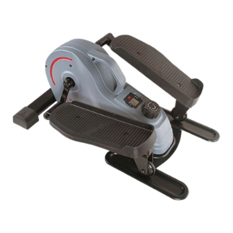
PORTABLE STAND UP ELLIPTICAL
English, Page 7~9
Español, Page 10~12
Français, Page 13~15
Deutsche, Seite 16~18
USER MANUAL
IMPORTANT! Please retain owner's manual for maintenance and adjustment instructions. Your satisfaction is
very important to us, PLEASE DO NOT RETURN UNTIL YOU HAVE CONTACTED US:
support@sunnyhealthfitness.com or 1- 877 - 90SUNNY (877-907-8669).
¡IMPORTANTE! Conserve el manual del propietario para las instrucciones de mantenimiento y ajuste. Su
satisfacción es muy importante para nosotros, NO DEVUELVA HASTA HABERNOS ONTACTADO:
support@sunnyhealthfitness.com ó 1- 877 - 90SUNNY (877-907-8669).
IMPORTANT! Veuillez conserver le manuel du propriétaire pour les instructions de réglage et d'entretien. Votre
satisfaction est très importante pour nous, VEUILLEZ NE PAS EFFECTUER DE RETOUR AVANT DE NOUS
AVOIR CONTACTÉ: support@sunnyhealthfitness.com ou 1- 877 - 90SUNNY (877-907-8669).
WICHTIG! Bitte bewahren Sie das Benutzerhandbuch für Wartungs- und Einstellanweisungen auf. Ihre
Zufriedenheit ist besonders wichtig für uns, BITTE SCHICKEN SIE DAS PRODUKT NICHT ZURÜCK, BEVOR
SIE SICH MIT UNS IN VERBINDUNG GESETZT HABEN: support@sunnyhealthfitness.com oder 1- 877 -
90SUNNY (877-907-8669).
SF-E3908
Advertisement
Table of Contents

Related Manuals for Sunny Health & Fitness SF-E3908


Summary of Contents for Sunny Health & Fitness SF-E3908
- Page 1 PORTABLE STAND UP ELLIPTICAL SF-E3908 USER MANUAL English, Page 7~9 IMPORTANT! Please retain owner’s manual for maintenance and adjustment instructions. Your satisfaction is very important to us, PLEASE DO NOT RETURN UNTIL YOU HAVE CONTACTED US: support@sunnyhealthfitness.com or 1- 877 - 90SUNNY (877-907-8669).
-
Page 2: Important Safety Information
IMPORTANT SAFETY INFORMATION We thank you for choosing our product. To ensure your safety and health, please use this equipment correctly. It is important to read this entire manual before assembling and using the equipment. Safe and effective use can only be achieved if the equipment is assembled, maintained, and used properly. -
Page 3: Informations De Sécurité Importantes
INFORMATIONS DE SÉCURITÉ IMPORTANTES Nous vous remercions d’avoir choisi notre produit. Pour votre santé et votre sécurité, veuillez utiliser correctement cet appareil. Il est important de lire entièrement le présent manuel avant d’assembler l’appareil et de l’utiliser. L’utilisation sûre et efficace n’est possible que si l’appareil est correctement assemblé, entretenu et utilisé. -
Page 4: Exploded Diagram
EXPLODED DIAGRAM... -
Page 5: Parts List
PARTS LIST Description Spec. Description Spec. Main Frame Bolt M6*12 Pedal Frame (R) Nylon Nut Pedal Frame (L) Belt Wheel Crank Belt J300 Magnetic Board C-clip Idler Wheel Shaft Bearing 6003 Axle for Crank Screw M5*15 Φ8.2*Φ16*1.5 7L/R Pedal Flat Washer Φ12*Φ10.2*6 8L/R Belt Cover... -
Page 6: Liste Des Éléments
LISTE DES ÉLÉMENTS Nº Description Spécification Qté Nº Description Spécification Qté Cadre Principal Boulon M6 × 12 Bloc Pédale (D) Écrou en Nylon Bloc Pédale (G) Roue de Courroie Manivelle Courroie J300 Panneau Magnétique Pince en C Arbre de la Roue Libre Roulement 6003 Axe de Manivelle... - Page 7 Ordering Replacement Parts (U.S. and Canadian Customers only) Please provide the following information in order for us to accurately identify the part(s) needed: The model number (found on cover of manual) The product name (found on cover of manual) ...
-
Page 8: Exercise Computer
EXERCISE COMPUTER SPECIFICATIONS SPEED--------------------------------------------0.0~999.9 MPH (Miles Per Hour) TIME-----------------------------------------------0:00~99:59MIN (Minutes) DIST (DISTANCE)-----------------------------0.0~9999ML (Miles) CAL (CALORIES)------------------------------0.0~9999KCAL (Kilocalories) FUNCTION KEYS: MODE: Press the red key repeatedly to select the desired value {TIME, SPEED, DIST (DISTANCE), CAL (CALORIES), SCAN}. Hold the key for 4 seconds to have all function values reset (total reset). -
Page 9: Adjusting The Tension
ADJUSTMENTS GUIDE ADJUSTING THE TENSION Adjust the tension by rotating the Tension Control Knob (No. 9) clockwise to increase the level of resistance. Rotate the Tension Control Knob (No. 9) counter-clockwise to decrease the level of resistance. Tension levels are set at Level 1 being the lowest and Level 8 being the highest. -
Page 10: Battery Replacement
BATTERY REPLACEMENT BATTERY PLASTIC CAP PLASTIC CAP LR44 BATTERY SEAT WIRE INSERTING HOLE 1. Remove the Meter (No. 10) from Main Frame (No. 1). Then disconnect the link wire of Inductor (No. 49) with the Meter (No. 10). 2. Remove the plastic cap from the back of Meter (No. 10). 3. -
Page 11: Especificaciones
COMPUTADORA DE EJERCICIOS ESPECIFICACIONES: SPEED (VELOCIDAD)----------------------0.0~999.9 MPH (Milla/Hora) TIME (TIEMPO)-------------------------------0:00~99:59 MIN DIST (DISTANCIA)---------------------------0.0~9999 ML (Milla) CAL (CALORÍAS)-----------------------------0.0~9999 KCAL (KCALORÍAS) FUNCIONES PRINCIPALES: MODE (MODO): Presione la tecla roja repetidamente para seleccionar el valor deseado {TIME (TIEMPO), SPEED (VELOCIDAD), DIST (DISTANCIA), CAL (CALORÍAS), SCAN (ESCANEO) }. -
Page 12: Guía De Ajustes
GUÍA DE AJUSTES AJUSTE DE LA TENSIÓN Ajuste la tensión al girar la Perilla de Control de Tensión (n.° 9) hacia la derecha para aumentar el nivel de resistencia. Gire la Perilla de Control de Tensión (n.° 9) hacia la izquierda para reducir el nivel de resistencia. Los niveles de tensión se establecen entre el Nivel 1, que es el más bajo, y el Nivel 8, que es el más alto. -
Page 13: Cambio De Pilas
CAMBIO DE PILAS PILA BATTERY TAPA DE PLASTIC TAPA DE PLASTIC PLASTIC CAP PLASTIC CAP LR44 COMPARTIMIEN ORIFICIO DE INSERCIÓN DE CABLE 1. Retire el Medidor (n.° 10) de la Estructura Principal (n.° 1). Luego, desconecte el cable de conexión del Inductor (n.° 49) con el Medidor (n.° 10). 2. -
Page 14: Spécifications
ORDINATEUR D’EXERCICE SPÉCIFICATIONS SPEED (VITESSE)----------------------0,0 à 999,9 MPH (milles à l’heure) TIME (DURÉE)---------------------------0:00 à 99:59 MIN (Minutes) DIST (DISTANCE)-----------------------0,0 à 9999 ML (milles) CAL (CALORIES)------------------------0,0 à 9999 KCAL (Kilocalories) TOUCHES DE FONCTION : MODE: Appuyer plusieurs fois sur la touche rouge pour sélectionner la valeur souhaitée {TIME (DURÉE), SPEED (VITESSE), DIST (DISTANCE), CAL (CALORIES), SCAN (BALAYAG)}. - Page 15 GUIDE DE RÉGLAGES RÉGLAGE DE LA RÉSISTANCE Régler la tension en tournant le Bouton de Contrôle de Tension (N dans le sens horaire pour augmenter le niveau de résistance. Tourner le Bouton de Contrôle de Tension (N 9) dans le sens antihoraire pour réduire le niveau de résistance.
-
Page 16: Remplacement Des Piles
REMPLACEMENT DES PILES PILES BATTERY COUVERCLE EN PLASTIQUE COUVERCLE EN PLASTIQUE PLASTIC CAP PLASTIC CAP LR44 COMPARTIMENT À PILES TROU D’INSERTION DU CÂBLE 1. Retirer le Compteur (N 10) du Cadre Principal (N 1). Débrancher ensuite le câble de raccordement de l’Inducteur (N 49) du Compteur (N 10). -
Page 17: Technische Daten
TRAININGSCOMPUTER TECHNISCHE DATEN SPEED (GESCHWINDIGKEIT)--------0.0~999,9MPH (Meile/Stunde) TIME (ZEIT)---------------------------------0:00~99:59MIN (Minuten) DIST (DISTANZ)---------------------------0.0~9999ML (Meile) CAL (KALORIEN)--------------------------0.0~9999KCAL (Kilokalorien) FUNKTIONSTASTEN: MODE: Drücken Sie wiederholt die rote Taste, um den gewünschten Wert auszuwählen {TIME (ZEIT), SPEED (GESCHWINDIGKEIT), DIST (DISTANZ), CAL (KALORIEN), SCAN}. Halten Sie die Taste 4 Sekunden lang gedrückt, um alle Funktionswerte zurückzusetzen (Totalreset). - Page 18 EINSTELLUNGSANLEITUNG EINSTELLEN DER SPANNUNG Stellen Sie die Spannung ein, indem Sie den Spannungseinstellknopf (Nr. 9) im Uhrzeigersinn drehen, um den Widerstand zu erhöhen. Drehen Sie den Spannungseinstellknopf (Nr. 9) gegen den Uhrzeigersinn, um den Widerstandsgrad zu reduzieren. Die Spannungsniveaus liegen zwischen Level 1 und Level 8, wobei Level 1 der niedrigste und 8 der höchste Widerstand ist.
-
Page 19: Austauschen Der Batterie
AUSTAUSCHEN DER BATTERIE BATTERIE BATTERY KUNSTSTOFFKAPPE KUNSTSTOFFKAPPE PLASTIC CAP PLASTIC CAP LR44 BATTERIEFACH DRAHTEINFÜHRUNGSÖFFNUNG 1. Entfernen Sie das Messgerät (Nr. 10) vom Hauptrahmen (Nr. 1). Trennen Sie dann das Verbindungskabel des Induktor (Nr. 49) vom Messgerät (Nr. 10). 2. Entfernen Sie den Kunststoffstreifen von der Rückseite des Messgerät (Nr. 10). 3.
Need help?
Do you have a question about the SF-E3908 and is the answer not in the manual?
Questions and answers