Advertisement
Quick Links
Quick Star t Guide
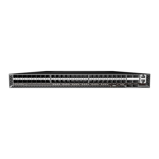
54-Port 25G/100G Fiber Ethernet Switch
AS7312-54XS | AS7316-54XS
1. Unpack the Switch and Check Contents
Rack Mounting Kit—2 front-post brackets, 2 rear-post
brackets, 20 screws, and 2 ear-locking screws
Power Cord (included with AC PSUs only)
Grounding Wire (included with DC PSUs only)
Console Cable—RJ-45 to DB-9
DC Power Cable (included with 48 VDC PSU only)
Dust Cover Kit—6 for QSFP port and 48 for SFP ports
Documentation—Quick Start Guide (this document)
and Safety and Regulatory Information
Note:
The switch has the Open Network Install
Environment (ONIE) software installer pre-loaded on the
switch, but no switch software image. Information about
compatible switch software can be found at
www.edge-core.com.
Caution:
The switch includes plug-in power supply (PSU)
and fan tray modules that are installed into its chassis. All
installed modules must have a matching airflow direction.
That is, if the installed power modules have a front-to-back
(F2B) airflow direction, all the installed fan tray modules
must also have a F2B airflow direction.
Note:
The switch drawings in this document are for
illustration only and may not match your particular switch
model.
2. Attach the Brackets
1
3
1
Attach each of the front- and rear-post brackets to the
switch using four of the included bracket screws.
www.edge-core.com
AS7312-54XS or
AS7316-54XS
1
2
2
Use an additional two screws to secure each of the rear-post
brackets at the mid-point on the sides of the switch.
3
Use the screws and cage nuts supplied with the rack to
secure the switch in the rack.
Caution:
Installing the switch in a rack requires two
people. One person should position the switch in the rack,
while the other secures it using the rack screws.
装置の吸排気に必要な領域を マニ ュ アル上に規定 し て
い る 。
3. Adjust Rear-Post Bracket Ears
1
Lock the position of the rear-post bracket ears using the
included position-locking screws.
You can also adjust the rear-post bracket ears to fit different
rack depths from 56 cm to 75 cm.
4. Ground the Switch
1
2
1
Ensure the rack is properly grounded and in compliance
with ETSI ETS 300 253. Verify that there is a good electrical
connection to the grounding point on the rack (no paint or
isolating surface treatment).
2
Attach the #14 AWG to the grounding point on the switch
rear panel. Then connect the other end of the wire to rack
ground.
For details on grounding the switch with a 12 VDC PSU in an
Open Rack, refer to the Edgecore ORSA-1U Open Rack Tray
Set Installation Guide.
Caution:
The earth connection must not be removed
unless all supply connections have been disconnected.
– 1 –
1
E062018-AP-R03
150200001566A
Advertisement

Related Manuals for Edge-Core AS7312-54XS


Summary of Contents for Edge-Core AS7312-54XS
- Page 1 Quick Star t Guide 54-Port 25G/100G Fiber Ethernet Switch AS7312-54XS | AS7316-54XS Use an additional two screws to secure each of the rear-post 1. Unpack the Switch and Check Contents brackets at the mid-point on the sides of the switch.
-
Page 2: Connect Power
Quick Start Guide 5. Connect Power 7. Perform Initial System Boot If the network operating system (NOS) installer is located on a network server, first connect the RJ-45 Management (Mgmt) port to the network using 100-ohm Category 5, 5e or better twisted-pair cable. (Not required if the NOS installer is located on attached storage.) Boot the switch. -
Page 3: Hardware Specifications
Hardware Specifications Switch Chassis Size (WxDxH) 438.4 x 473 x 44 mm (17.26 x 18.62 x 1.73 inches) Weight AS7312-54XS: 9.43 kg (20.78 lb), with two installed PSUs AS7316-54XS: 9.6 kg (21.164 lb), with two installed PSUs Temperature Operating: 0° C to 45° C (32° F to 123° F) Storage: -40°... - Page 4 快 速 入 门 指 南 54 端口 25G/100G 以太网交换机 AS7312-54XS | AS7316-54XS 使用机架随附的螺丝和卡式螺母将交换机固定到支架 1. 打开交换机的包装并检查内装物 上。 警告:将此交换机安装在机架中时需要两个人。一个人 AS7312-54XS 或 将交换机放置在机架中,同时另一个人用机架螺丝将其 AS7316-54XS 固定。 装置の吸排気に必要な領域を マニ ュ アル上に規定 し て い る 。 前柱支架 x2, 带可调节吊耳的后柱支架 x2, 支架螺丝 x20, 后支架吊耳位置 - 锁定螺丝 x2 3.
- Page 5 5. 连接电源 7. 执行初次系统启动 如果网络操作系统 (NOS) 安装程序位于网络服务器中, 应首先使用 5、5e 类或以上双绞线将 RJ-45 管理 (Mgmt) 端口连接到网络。 注意,RJ-45 Mgmt 管理仅支 持 1000 Mbps 模式。 (NOS 安装程序位于相连的存储装 置中时不需要。) 启动交换机。等待 ONIE 软件找到和执行 NOS 安装程 序,然后等待安装程序加载 NOS 软件映像。 以后交换机启动时将跳过 ONIE 而直接运行 NOS 软件。 注意: 有关 ONIE 软件位置选项和设置的详细信息,请 参见...
- Page 6 交换机机箱 尺寸 438.4 x 473 x 44 mm (17.26 x 18.62 x 1.73 英寸 ) ( 宽 x 深 x 高 ) 重量 AS7312-54XS: 9.43 kg (20.78 磅 ),含附带的两 个 PSU AS7316-54XS: 9.6 kg (21.164 磅 ),含附带的两 个 PSU 温度...
- Page 7 快速入門指南 54 埠 25G/100G 乙太網路交換器 AS7312-54XS | AS7316-54XS 額外使用兩個螺絲,將後柱托架各別固定在交換器側邊 1. 拆開交換器包裝並檢查內容物 中間處。 使用隨機櫃提供的螺絲及籠罩螺帽,將交換器固定在機 AS7312-54XS 或 櫃上。 AS7316-54XS 注意: 需要兩個人,將交換器裝到機櫃上。一人負責固 定交換器在機櫃上之位置,另一人負責用機櫃螺絲固 前柱托架 x2、後柱托架附可調固定片 x2、托架螺 定。 絲 x20、後托架固定片位置-定位螺絲 x2 装置の吸排気に必要な領域を マニ ュ アル上に規定 し て い る 。 電源線 (僅隨附於 AC PSU)...
- Page 8 5. 連接電源 7. 執行初次系統啟動 若網路作業系統 (NOS)安裝程式位於網路伺服器,先 使用 5-ohm 第 5 類、5e 類或更優之雙絞線電纜,連接 RJ-45 管理 (Mgmt)埠至網路。請注意,RJ-45 Mgmt 連接埠僅支援 1000 Mbps 模式。 (若 NOS 安裝程式位 於所附儲存設備中,則不需要。) 啟動交換器。等待 ONIE 軟體找尋並執行 NOS 安裝程 式,並等待安裝程式載入 NOS 軟體映像檔。 之後交換器啟動時,會跳過 ONIE,直接運行 NOS 軟 體。 關於詳細軟體選項及 ONIE 設定說明,請參閱網 說明:...
- Page 9 硬體規格 交換器機箱 438.4 x 473 x 44 mm (17.26 x 18.62 x 1.73 英吋 ) 尺寸 (WxDxH) AS7312-54XS: 9.43 kg (20.78 磅 ),含兩個安裝 重量 AS7316-54XS: 9.6 kg (21.164 磅 ),含兩個安裝 操作 : 0°C 至 45°C (32°F 至 123°F) 溫度 儲存 : -40°C 至 70°C (-40°F 至 158°F) 操作...
Need help?
Do you have a question about the AS7312-54XS and is the answer not in the manual?
Questions and answers