Advertisement
Available languages
Available languages
Quick Start Guide
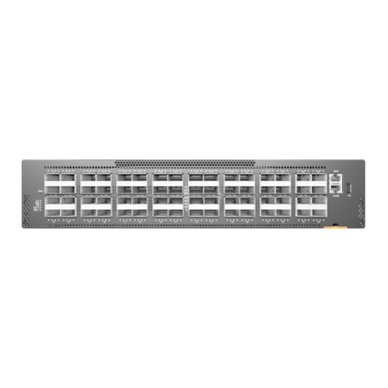
64-Port 100G Top-of-Rack Switch
AS7816-64X
1.
100G Top-of-Rack Switch AS7816-64X
2.
Rack mounting kit—2 front-post brackets, 2 rear-post
brackets, 20 screws, and 2 ear-locking screws
3.
AC power cord
4.
DC power cable included with 48VDC PSU only (optional)
5.
Console cable—RJ-45 to DB-9
Caution:
The switch includes plug-in power supply (PSU)
and fan tray modules that are installed into its chassis. All
installed modules must have a matching airflow direction.
That is, if the installed power modules have a front-to-back
(F2B) airflow direction, all the installed fan tray modules
must also have a F2B airflow direction.
Attention:
Le commutateur comprend des modules
d'alimentation et de bac de ventilateurs installés sur son
châssis. Tous les modules installés doivent avoir une
direction de circulation d'air correspondante. C'est-à-dire
que tous les modules doivent avoir la même direction de
circulation d'air: avant vers arrière (F2B), ou arrière vers
avant (B2F).
Note:
The switch has the Open Network Install
Environment (ONIE) software installer preloaded on the
switch, but no switch software image. Information about
compatible switch software can be found at
www.edge-core.com.
Note:
The switch drawings in this document are for
illustration only and may not match your particular switch
model.
1
Attach the Brackets
3
1.
Attach each of the front- and rear-post brackets to the switch
using four of the included bracket screws.
2.
Use an additional two screws to secure each of the rear-post
brackets at the mid-point on the sides of the switch.
3.
Use the screws and cage nuts supplied with the rack to secure
the switch in the rack.
Package Contents
1
2
1
2
1
3
4
6.
Grounding kit—One grounding lug, 2 M5 screws and 2
washers (for AC PSU)
7.
Grounding kit—One grounding lug, 4 ring lugs, 2 M5 screws
and 2 washers (for DC PSU)
8.
Documentation—Quick Start Guide (this document) and
Safety and Regulatory Information
2
Adjust Rear-Post Bracket Ears
1.
Lock the position of the rear-post bracket ears using the included
position-locking screws.
You can also adjust the rear-post bracket ears to fit different rack
depths from 56 cm to 75 cm.
3
Ground the Switch
1
1.
Ensure the rack is properly grounded and in compliance with
ETSI ETS 300 253. Verify that there is a good electrical
connection to the grounding point on the rack (no paint or
isolating surface treatment).
2.
Attach a #10 AWG grounding wire (not included) to the
grounding point on the switch rear panel. Then connect the
other end of the wire to rack ground.
– 1 –
www.edge-core.com
5
6
7
1
2
8
E032024-CS-R06
150200002012A
Advertisement
Table of Contents

Related Manuals for Edge-Core AS7816-64X


Summary of Contents for Edge-Core AS7816-64X
- Page 1 Quick Start Guide 64-Port 100G Top-of-Rack Switch www.edge-core.com AS7816-64X Package Contents 100G Top-of-Rack Switch AS7816-64X Grounding kit—One grounding lug, 2 M5 screws and 2 washers (for AC PSU) Rack mounting kit—2 front-post brackets, 2 rear-post brackets, 20 screws, and 2 ear-locking screws Grounding kit—One grounding lug, 4 ring lugs, 2 M5 screws...
-
Page 2: Verify Switch Operation
Quick Start Guide Verify Switch Operation Caution: The earth connection must not be removed unless all supply connections have been disconnected. Attention: Le raccordement à la terre ne doit pas être retiré sauf si toutes les connexions d’alimentation ont été débranchées. -
Page 3: Hardware Specifications
Quick Start Guide As connections are made, check the port status LEDs to be sure the links are valid. Each QSFP28 port has four LEDs that indicate valid links in the following modes: 1 LED Blue — 100 Gbps mode ... -
Page 4: Краткое Руководство
64-портовый коммутатор 100G в верхней части стойки www.edge-core.com AS7816-64X Стоечный коммутатор верхнего уровня 100G AS7816-64X Консольный кабель RJ-45 - DB-9 Комплект для монтажа в стойке – 2 кронштейна с передними опорами, Комплект заземления— Один наконечник заземления, 2 винта M5 и 2 2 кронштейна... - Page 5 Quick Start Guide Проверка работоспособности коммутатора Внимание! Удаление заземляющего соединения допускается только в случае полного разъединения всех подключений к блоку питания. Подключите питание Чтобы проверить основные функции коммутатора, проверьте работу индикаторов системы. При работе в нормальном режиме индикаторы PSU1/PSU2, Diag (Диагностика) и...
- Page 6 Quick Start Guide После подключения всех устройств проверьте правильность установки связи по индикаторам состояния портов. Каждый из портов QSFP28 оснащен четырьмя индикаторами, которые показывают действующие соединения в следующих режимах: 1 синий индикатор – режим 100 Гбит/с 1 оранжевый индикатор – режим 40 Гбит/с ...
Need help?
Do you have a question about the AS7816-64X and is the answer not in the manual?
Questions and answers