
Related Manuals for Edge-Core AS4600-54T


Summary of Contents for Edge-Core AS4600-54T
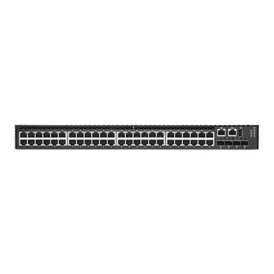
- Page 1 AS4600-54T 48 GE port with 4*10G SFP+ with 2 Expansion Slots I n s t a l l a t i o n G u i d e Data Center Switch www.edge-core.com.au...
- Page 2 Installation Guide AS4600-54T 48 GE port with 4*10G SFP+ with 2 Expansion Slots Data Center Switch with 48 10/100/1000BASE-T (RJ-45) Ports, 4 10GBASE SFP+ Ports, 2 Slots for Optional Single-Port 40GBASE QSFP+ Modules 2 Power Supply Units, and 2 Fan Trays (F2B or B2F Airflow)
-
Page 3: How To Use This Guide
How to Use This Guide This guide includes detailed information on the switch hardware, including network ports, power, cabling requirements, as well as plug-in modules and transceivers. This guide also provides general installation guidelines and recommended procedures. To deploy this switch effectively and ensure trouble- free operation, you should first read the relevant sections in this guide so that you are familiar with all its hardware components. - Page 4 How to Use This Guide ◆ Chapter 5 - Port Connections—Includes information on network interfaces, installing optional transceivers, and cabling specifications. ◆ Chapter 6 - Switch Management—Connecting to the switch for management, and information on the system status LEDs. ◆ Appendix A - Troubleshooting—Information for troubleshooting switch installation and operation.
-
Page 5: Table Of Contents
Contents How to Use This Guide Contents Figures Tables 1 Switch Description Overview Key Hardware Components Key Technical Specifications Data Center Deployment Rack Cooling 2 Installation Overview Package Contents Switch Installation Tasks 3 Switch Chassis General Installation Guidelines How to Install the Switch in a Rack Rack-Mounting Items Rack-Mount Procedure Switch Cooling Requirements... - Page 6 Contents Grounding the Chassis How to Connect to AC Power 5 Port Connections Cable Labeling and Connection Records Understanding the Port Status LEDs How to Install an SFP/SFP+/QSFP+ Transceiver How to Connect to Twisted-Pair Copper Ports Copper Cabling Guidelines 10/100BASE-TX Pin Assignments 1000BASE-T Pin Assignments Connection Procedure How to Connect to SFP/SFP+ Fiber Optic Ports...
-
Page 7: Figures
Figures Figure 1: Front Panel Figure 2: Rear Panel Figure 3: Cloud Data Center Deployment Figure 4: Converged Ethernet Data Center Deployment Figure 5: F2B Airflow Cooling Figure 6: B2F Airflow Cooling Figure 7: Installing the Switch in a Rack Figure 8: Grounding Terminal Figure 9: Connecting AC Power Figure 10: System LEDs... - Page 8 Figures Figure 30: System Status LEDs Figure 31: Console Port Figure 32: Console Port Connection Figure 33: Management Port – 8 –...
-
Page 9: Tables
Tables Table 1: Key Technical Specifications Table 2: AC Power Supply Unit Specifications Table 3: Power Supply Unit LED Table 4: Port Status LEDs Table 5: Maximum Twisted-Pair Copper Cable Lengths Table 6: 10/100BASE-TX MDI and MDI-X Port Pinouts Table 7: 1000BASE-T MDI and MDI-X Port Pinouts Table 8: Maximum 10 Gigabit Ethernet Fiber Cable Lengths Table 9: Maximum Gigabit Ethernet Fiber Cable Lengths Table 10: Maximum 40 Gigabit Ethernet Fiber Cable Lengths... - Page 10 ◆ “Data Center Deployment” on page 14 Overview Thank you for choosing the AS4600-54T switch system. This switch is built with leading-edge technology to deliver reliable high-performance connectivity for your data network. The AS4600-54T switch is a high-performance top-of-rack switch, designed for data center operating environments.
-
Page 11: Switch Description Overview
Chapter 1 | Switch Description Overview Key Hardware The switch consists of several key hardware components. This manual describes each specific component, or related components, together with their installation Components requirements and procedures in each chapter. To understand each component in detail, refer to the relevant section. -
Page 12: Figure 2: Rear Panel
Chapter 1 | Switch Description Overview Console Port The RJ-45 connector on the front panel labeled “Console” provides an out-of-band serial connection to a terminal or a PC running terminal emulation software. The port can be used for performing switch monitoring and configuration. For more information, see “How to Connect to the Console Port”... -
Page 13: Key Technical Specifications
Chapter 1 | Switch Description Key Technical Specifications 40G QSFP+ Slots (Optional) The switch contains four Quad Small Form Factor Pluggable Plus (QSFP+) transceiver slots that operate up to 40 Gbps full duplex. For more information, see “How to Connect to QSFP+ Fiber Optic Ports” on page Power Supply Units The switch supports dual hot-swappable AC power supply units (PSUs). -
Page 14: Data Center Deployment
Chapter 1 | Switch Description Data Center Deployment Table 1: Key Technical Specifications Item Specification Temperature Operating: 0 °C to 50 °C (32 °F to 122 °F) Storage: -40 °C to 70 °C (-40 °F to 158 °F) Humidity Operating: 10% to 90% (non-condensing) Out-of-Band Management RS-232 RJ-45 console port Ethernet RJ-45 Management port... -
Page 15: Rack Cooling
Chapter 1 | Switch Description Data Center Deployment In many data center configurations, Ethernet connections link servers and data networks, and Fibre Channel connections link servers to storage networks. This switch enables the creation of a converged network, which employs lossless Ethernet connections between FCOE storage, servers, and other data network switches. -
Page 16: Figure 5: F2B Airflow Cooling
Chapter 1 | Switch Description Data Center Deployment Figure 5: F2B Airflow Cooling Hot Aisle Cool Aisle ToR Switch Servers Front of Rack Rear of Rack When mounted in a rack with other network equipment that may have a back-to- front (B2F) airflow direction, the top-of-rack switch includes two fan trays that reverse the airflow direction through the switch. -
Page 17: Installation Overview
After unpacking the switch, check the contents to be sure you have received all the components. ◆ AS4600-54T Top-of-Rack Switch equipped with either one or two PSUs ◆ Rack Mounting Kit containing two standard brackets and eight screws for attaching the brackets to the switch ◆... -
Page 18: Figure 7: Installing The Switch In A Rack
Chapter 2 | Installation Overview Switch Installation Tasks Task 1 Unpack Package and Check Contents Unpack your switch and check the package contents to be sure you have received all the items. See “Package Contents” on page Task 2 Install the Chassis The switch is designed to be installed in a standard 19-inch equipment rack. -
Page 19: Figure 8: Grounding Terminal
Chapter 2 | Installation Overview Switch Installation Tasks Task 3 Ground the Switch Before powering on the switch, ground the switch to earth. Ensure the rack in which the switch is to be mounted is properly grounded and in compliance with ETSI ETS 300 253. -
Page 20: Figure 9: Connecting Ac Power
Chapter 2 | Installation Overview Switch Installation Tasks Figure 9: Connecting AC Power Install one or two universal AC power Connect an external AC power source supply units in the switch. to the power supply units. Task 5 Verify Switch Operation Verify basic switch operation by checking the system LEDs. -
Page 21: Figure 10: System Leds
Chapter 2 | Installation Overview Switch Installation Tasks Figure 10: System LEDs System Status LEDs. Task 6 Make Initial Configuration Changes At this point you may need to make a few basic switch configuration changes before connecting to the network. It is suggested to connect to the switch console port to perform this task. -
Page 22: Figure 12: Making A Connection To An Sfp+ Port
Chapter 2 | Installation Overview Switch Installation Tasks For information on initial switch configuration: Refer to the Administrator’s Guide. Task 7 Install Transceivers and Connect Cables Install SFP+ or QSFP+ transceivers and connect network cables to port interfaces: ◆ For RJ-45 ports, use 100-ohm Category 3, 5 or 5e twisted-pair cable for 10BASE- T connections, or Category 5, 5e or better cable for 100/1000BASE-T connections. -
Page 23: Figure 13: Making A Connection To An Qsfp+ Port
Chapter 2 | Installation Overview Switch Installation Tasks Figure 13: Making a Connection to an QSFP+ Port Install QSFP+ transceivers. Connect fiber optic cabling to the ports. – 23 –... -
Page 24: Switch Chassis
Switch Chassis The switch is designed to be installed in a standard 19-inch equipment rack. Before continuing with switch installation, first review the general guidelines and switch cooling requirements in this chapter. This chapter includes these sections: ◆ “General Installation Guidelines” on page 24 ◆... -
Page 25: How To Install The Switch In A Rack
Chapter 3 | Switch Chassis How to Install the Switch in a Rack How to Install the Switch in a Rack When rack mounting the switch, pay particular attention to the following factors: ◆ Rack Types: You can use any standard EIA 19-inch equipment rack with either two or four posts. -
Page 26: Figure 14: Attaching The Brackets
Chapter 3 | Switch Chassis How to Install the Switch in a Rack Attach the brackets to the device using the screws provided in the Rack Mounting Kit. Figure 14: Attaching the Brackets Use the screws provided in the Rack Mounting Kit. -
Page 27: Switch Cooling Requirements
Chapter 3 | Switch Chassis Switch Cooling Requirements If installing multiple switches, repeat steps 1 to 4 to mount the switches following your rack plan. Switch Cooling Requirements Wherever the switch is located, be sure to pay close attention to switch cooling requirements. -
Page 28: Rack Cooling
Chapter 3 | Switch Chassis Switch Cooling Requirements Rack Cooling When mounting the switch in an enclosed rack or cabinet, be sure to check the following guidelines to prevent overheating: ◆ Make sure that enough cool air can flow into the enclosure for the equipment it contains. -
Page 29: How To Replace A Fan Tray
Chapter 3 | Switch Chassis Switch Cooling Requirements The following figure shows a fan tray being installed in the switch. Figure 17: Fan Tray Label indicates airflow direction How to Replace a Fan The switch system is shipped with two fan trays installed. If a fan failure is detected Tray (see “Understanding the System Status LEDs”... -
Page 30: Optional Expansion Module
Chapter 3 | Switch Chassis Optional Expansion Module Optional Expansion Module The switch supports two optional hot-swappable, single-port 40G QSFP+ media expansion modules that install in the rear of the switch chassis. The module’s QSFP+ port supports standard 40G QSFP+ transceivers. The 40GBASE transceivers can operate at 40 Gbps or 4x10 Gbps full duplex, with support for flow control. -
Page 31: Figure 19: Installing An Optional Module
Chapter 3 | Switch Chassis How to Install an Optional Expansion Module Figure 19: Installing an Optional Module Module Slot Expansion Module Holding the module level, guide it into the carrier rails on each side and gently push it all the way into the slot, ensuring that it firmly engages with the connector. -
Page 32: Power And Grounding
Power and Grounding This chapter focuses on the switch power supplies, how to install them, and how to power-on the switch. Connecting the switch to ground is also covered. This chapter includes these sections: ◆ “Power Supply Units” on page 32 ◆... -
Page 33: Figure 20: Ac Power Supply Unit
Chapter 4 | Power and Grounding Power Supply Units Figure 20: AC Power Supply Unit AC Power Socket Release Lever Power Supply Unit LED Table 2: AC Power Supply Unit Specifications Item Description AC Input 100-240 VAC, 50-60 Hz, 3.5 A DC Output 5 VDC @ 0.5 A 12 VDC @ 25 A... -
Page 34: Grounding The Chassis
Chapter 4 | Power and Grounding Grounding the Chassis Grounding the Chassis The switch chassis must be connected to ground to ensure proper operation and to meet electromagnetic interference (EMI) and safety requirements. The rear panel of the switch chassis includes a single-screw grounding terminal. It must be connected to ground to ensure proper operation and to meet electromagnetic interference (EMI) and safety requirements. -
Page 35: How To Connect To Ac Power
Chapter 4 | Power and Grounding How to Connect to AC Power Caution: The earth connection must not be removed unless all supply connections have been disconnected. How to Connect to AC Power To supply AC power to the switch, first verify that the external AC power supply can provide the power requirement as listed in Table 2 for each PSU installed. - Page 36 Chapter 4 | Power and Grounding How to Connect to AC Power Plug the power cord into a grounded, 3-pin, AC power source. Note: For international use, you may need to change the AC power cord. You must use a cord set that has been approved for the socket type in your country. Insert the plug on the other end of the power cord directly into the socket on the AC PSU.
-
Page 37: Port Connections
Port Connections This chapter focuses on making connections to switch network interfaces, including how to install optional transceivers, and details on network cable specifications. This chapter includes these sections: ◆ “Cable Labeling and Connection Records” on page 38 ◆ “Understanding the Port Status LEDs” on page 39 ◆... -
Page 38: Cable Labeling And Connection Records
Chapter 5 | Port Connections Cable Labeling and Connection Records Cable Labeling and Connection Records When planning a network installation, it is essential to label the opposing ends of cables and to record where each cable is connected. Doing so will enable you to easily locate inter-connected devices, isolate faults and change your topology without need for unnecessary time consumption. -
Page 39: Understanding The Port Status Leds
Chapter 5 | Port Connections Understanding the Port Status LEDs Understanding the Port Status LEDs The switch includes LED indicators for each port to indicate link status and network activity. The port LEDs are shown below and described in the following table. Figure 23: Port Status LEDs Management Port 10/100 Mbps Link/ Port 1-48 1000 Mbps Link/Activity LEDs... -
Page 40: How To Install An Sfp/Sfp+/Qsfp+ Transceiver
Chapter 5 | Port Connections How to Install an SFP/SFP+/QSFP+ Transceiver Table 4: Port Status LEDs (Continued) Condition Status 10G SFP+ Ports (49-52) Link/Activity On/Blinking Green Port has a valid 10 Gbps link. Blinking indicates (1/10 Gbps) activity on the port. On/Blinking Amber Port has a valid 1000 Mbps link. -
Page 41: How To Connect To Twisted-Pair Copper Ports
Chapter 5 | Port Connections How to Connect to Twisted-Pair Copper Ports ◆ 1000BASE-LX ◆ 100BASE-FX ◆ 1000BASE-T Note: SFP/SFP+/QSFP+ transceivers are hot-swappable. The switch does not need to be powered off before installing or removing a transceiver. Note: SFP/SFP+/QSFP+ transceivers are not provided in the switch package. Note: Transceiver slots used for 10G or 40G DAC connections are described in the section... -
Page 42: Copper Cabling Guidelines
Chapter 5 | Port Connections How to Connect to Twisted-Pair Copper Ports Table 5: Maximum Twisted-Pair Copper Cable Lengths (Continued) Cable Type Maximum Cable Length Connector 10BASE-T Category 3 or better 100-ohm UTP 100 m (328 ft) RJ-45 Copper Cabling To ensure proper operation when installing the switch into a network, make sure Guidelines that the current cables are suitable for 10BASE-T, 100BASE-TX, or 1000BASE-T... -
Page 43: 1000Base-T Pin Assignments
Chapter 5 | Port Connections How to Connect to Twisted-Pair Copper Ports Table 6: 10/100BASE-TX MDI and MDI-X Port Pinouts MDI Signal Name MDI-X Signal Name Transmit Data plus (TD+) Receive Data plus (RD+) Transmit Data minus (TD-) Receive Data minus (RD-) Receive Data plus (RD+) Transmit Data plus (TD+) Receive Data minus (RD-) -
Page 44: Connection Procedure
How to Connect to SFP/SFP+ Fiber Optic Ports The AS4600-54T switch includes 4 slots for 10 Gigabit Ethernet SFP+ or Gigabit Ethernet SFP fiber-optic transceivers. -
Page 45: Connection Procedure
Chapter 5 | Port Connections How to Connect to SFP/SFP+ Fiber Optic Ports Table 8: Maximum 10 Gigabit Ethernet Fiber Cable Lengths (Continued) Fiber Size Fiber Bandwidth Maximum Cable Length Connector 62.5/125 micron multimode 200 MHz/km 2-33 m (7-108 ft.) 50/125 micron multimode 400 MHz/km 2-66 m (7-216 ft.) -
Page 46: Figure 26: Making Connections To An Sfp+ Transceiver
Chapter 5 | Port Connections How to Connect to SFP/SFP+ Fiber Optic Ports Check that the fiber terminators are clean. You can clean the cable plugs by wiping them gently with a clean tissue or cotton ball moistened with a little ethanol. -
Page 47: How To Connect To Qsfp+ Fiber Optic Ports
Chapter 5 | Port Connections How to Connect to QSFP+ Fiber Optic Ports How to Connect to QSFP+ Fiber Optic Ports The switch includes two slots for expansion modules that support 40G QSFP+ fiber- optic transceivers. Note that 40G fiber optic ports can provide either one 40 Gbps full-duplex link, four independent 10G fiber optic links. -
Page 48: Figure 27: Connecting To A Qsfp+ Transceiver
Chapter 5 | Port Connections How to Connect to QSFP+ Fiber Optic Ports Connect one end of the cable to the QSFP+ port on the switch and the other end to the QSFP+ port on the other device. Since QSFP+ connectors are keyed, the cable can only be attached in the correct orientation. -
Page 49: Dac Connections
Chapter 5 | Port Connections DAC Connections DAC Connections Direct Attach Cable (DAC) is a method of connecting two SFP+/QSFP+ interfaces without using optics and fiber cable. A fixed length of twinax copper cable is terminated at each end with physically-compliant SFP+/QSFP+ transceivers that do not include all their normal electronic and optical components. -
Page 50: Figure 28: Making Dac Connections (10G)
Chapter 5 | Port Connections DAC Connections Figure 28: Making DAC Connections (10G) 10G SFP+ DAC Cable Figure 29: Making DAC Connections (40G) 40G SFP+ DAC Cable Plug the other end of the twinax cable into an SFP+/QSFP+ slot on the switch. Check that the Link LED on the switch turns on green to indicate that the connection is valid. -
Page 51: Switch Management
Switch Management The switch includes a management agent that allows you to configure or monitor the switch using its embedded management software. To manage the switch, you can make a direct connection to the console port (out-of-band), or you can manage it through a network connection (in-band) using Telnet, Secure Shell (SSH), a web browser, or SNMP-based network management software. -
Page 52: Understanding The System Status Leds
Chapter 6 | Switch Management Understanding the System Status LEDs Understanding the System Status LEDs The switch includes a display panel of key system LED indicators. The LEDs, which are located on the front panel, are shown below and described in the following table. -
Page 53: How To Connect To The Console Port
Chapter 6 | Switch Management How to Connect to the Console Port How to Connect to the Console Port The RJ-45 Console port on the switch’s front panel is used to connect to the switch for out-of-band console configuration. The console device can be a PC or workstation running a VT-100 terminal emulator, or a VT-100 terminal. -
Page 54: Figure 32: Console Port Connection
Chapter 6 | Switch Management How to Connect to the Console Port ◆ Stop bit—One ◆ Data bits—8 ◆ Flow control—none Figure 32: Console Port Connection Follow these steps to connect to the Console port: Attach one end of the included RJ-45-to-DB-9 serial cable to a DB-9 COM port connector on a management PC. -
Page 55: How To Connect To The Mgmt Port
Chapter 6 | Switch Management How to Connect to the Mgmt Port How to Connect to the Mgmt Port The port on the switch’s front panel labeled “Mgmt” provides an out-of-band network connection to the management agent of the switch using TCP/IP over Ethernet. -
Page 56: A Troubleshooting
Troubleshooting Diagnosing LED Indicators Table 15: Troubleshooting Chart Symptom Action ◆ Pwr 1/Pwr 2 LED is Off Check connections between the PSU, the power cord and the wall outlet. ◆ Contact your dealer for assistance. ◆ Pwr 1/Pwr 2 LED is on Power cycle the PSU to try and clear the condition. -
Page 57: Power And Cooling Problems
Chapter A | Troubleshooting Power and Cooling Problems Power and Cooling Problems If a power indicator does not turn on when the power cord is plugged in, you may have a problem with the power outlet, power cord, or PSU. However, if the switch powers off after running for a while, check for loose power connections, power losses or surges at the power outlet. -
Page 58: Index
Index Numerics installation power requirements 10/100 PIN assignments site requirements 1000BASE-SX fiber cable Lengths installation troubleshooting 1000BASE-T PIN assignments introduction 10GBASE fiber cable lengths 10GBASE-LR fiber cable lengths laser safety LC port connections air flow requirements LED indicators DIAG port power brackets, attaching buffer size... - Page 59 Index specifications environmental status LEDs surge suppressor, using web-based management – 59 –...
- Page 60 Declaration of Conformity (DoC) can be obtained from www.edge-core.com -> support -> download -> declarations & certifications AS4600-54T E122013-AP-R01 150200000566...
Need help?
Do you have a question about the AS4600-54T and is the answer not in the manual?
Questions and answers