Table of Contents
Advertisement
Quick Links
Quick Start Guide
Ethernet Switch
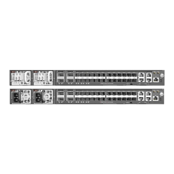
AS7535-28XB
1.
AS7535-28XB (includes 2 PSUs and 6 fan trays)
2.
Rack Mounting Kit—2 brackets and 8 screws
3.
Grounding kit—grounding lug, 2 screws, and 2 washers
1
2
3
1.
2 x DC or AC PSUs
2.
2 x 100G QSFP28 ports
3.
2 x 400G QSFP-DD ports
4.
24 x 25G SFP28 ports
5.
Product tag
6.
Management I/O: 1000BASE-T RJ-45, RJ-45 console,
Micro-USB console, reset button
1
1.
PSU LED: Green (OK), Amber (fault)
2.
QSFP-DD Port LEDs: Blue (400G), Cyan (200G), Green (100G),
Yellow (50G)
3.
QSFP28 Port LEDs: Green (100G), Cyan (50G), Magenta (40G),
Blue (25G), Yellow (10G)
4.
SFP28 Port LEDs: Blue (25G), Green (10G), Cyan (1G)
FRU Replacement
PSU Replacement
1.
Remove the power cord.
2.
Press the release latch and
remove the PSU.
3.
Install replacement PSU.
4
6
5
4
2
5
3
Fan Tray Replacement
1.
Loosen the fan tray screw.
2.
Pull out and remove the fan
tray.
3.
Install replacement fan tray.
Package Contents
1
2
4.
(Optional) AC power cord
5.
Documentation—Quick Start Guide (this document) and Safety
and Regulatory Information
Overview
8
7
9
10
11
7.
BITS/ToD RJ-45 timing ports
8.
10MHz/1PPS I/O
9.
GNSS antenna
10.
USB Type C storage port
11.
RJ-45 alarm port
12.
6 x fan trays
13.
Grounding screw
Status LEDs
5.
System LEDs:
PSU1/2 — Green (OK), Amber (fault)
DIAG — Green (OK), Orange (fault detected)
FAN — Green (OK), Orange (fault)
LOC — Blinking Blue (OK)
ALARM — Green (OK), Red (alarm)
6.
RJ-45 Management Port LEDs: Left (link), Right (activity)
7.
BITS/ToD LEDs: Green (valid BITS), Blinking Green (1PPS ToD)
– 1 –
www.edge-core.com
3
4
12
6
7
5
13
E052022-CS-R01
150200002489A
Advertisement
Table of Contents

Related Manuals for Edge-Core AS7535-28XB


Summary of Contents for Edge-Core AS7535-28XB
- Page 1 Quick Start Guide Ethernet Switch www.edge-core.com AS7535-28XB Package Contents AS7535-28XB (includes 2 PSUs and 6 fan trays) (Optional) AC power cord Rack Mounting Kit—2 brackets and 8 screws Documentation—Quick Start Guide (this document) and Safety and Regulatory Information Grounding kit—grounding lug, 2 screws, and 2 washers...
- Page 2 (ONIE) software installer preloaded, but no software image. surface treatment). Information about compatible software can be found at Attach Grounding Wire www.edge-core.com Attach the grounding wire (#14 AWG/1.5 mm , green with yellow stripe) Note: The drawings in this document are for illustration only to the grounding point on the device’s rear panel or side panel.
- Page 3 Quick Start Guide The following transceivers are supported in the QSFP28 ports: Caution: Before connecting power supply cables to the 100GBASE-SR4, PSM4, LR4, ER4, ZR4, CR4, AOC device, ensure that power to the feed lines is turned off at the 40GBASE-SR4, PSM4, LR4 ...
- Page 4 UL (CSA 22.2 No 62368-1 & UL 62368-1) CB (IEC/EN 60950-1 & IEC/EN 62368-1) Warranty Information and Technical Support Registering your product enables you to receive a more efficient warranty service. Be sure to register at www.edge-core.com. – 4 –...
Need help?
Do you have a question about the AS7535-28XB and is the answer not in the manual?
Questions and answers