SteppIR 4 Element Yagi Instruction Manual
Hide thumbs
Also See for 4 Element Yagi:
- Instruction manual (42 pages) ,
- Installation instructions manual (20 pages)

Related Manuals for SteppIR 4 Element Yagi


Summary of Contents for SteppIR 4 Element Yagi
- Page 1 4 Element Yagi Instruction Manual REV 3.0 September 2012 2112 116TH AVE NE SUITE 1-5, BELLEVUE WA, 98004 WWW.STEPPIR.COM TEL: (425)-453-1910 FAX: (425)-462-4415...
- Page 2 Install the OPTIONAL 6m passive element kit 25-26 Install the boom truss assembly 26-27 SteppIR Performance 28-30 Options for your SteppIR Yagi 31-32 Limited Warranty Specifications 2112 116TH AVE NE SUITE 1-5, BELLEVUE WA, 98004 WWW.STEPPIR.COM TEL: (425)-453-1910 FAX: (425)-462-4415...
- Page 3 SteppIR Antennas - 4 Element 2112 116TH AVE NE SUITE 1-5, BELLEVUE WA, 98004 WWW.STEPPIR.COM TEL: (425)-453-1910 FAX: (425)-462-4415...
- Page 4 SteppIR Antennas - 4 Element Assembly Kit Bill of Materials 4E Boom Assembly Hardware Kit 72-0004-01 PART NUMBER DESCRIPTION 60-0004-21 2” LONG U-BOLT WITH SADDLE 60-0006 2-1/2” U-BOLT WITH SADDLE 60-0029 3” x 1/4” BOLT 60-0030 1/4” NYLOCK NUT 60-0046 5/16”...
- Page 5 SteppIR Antennas - 4 Element Assembly Kit Bill of Materials 4E Terminal Strip / EHU Pack 72-0008-01 PART NUMBER DESCRIPTION 09-0001 ELECTRICAL TAPE 60-6000-40 4” HOSE CLAMP 70-1102-21 1-1/2” ELECTRICAL ENCLOSER 10-1029-01 CONNECTOR PROTECTOR (bulb grease CP-1) 20-6020-8 8 – POSITION CONNECTOR 20-6020-1 1 –...
- Page 6 SteppIR Antennas - 4 Element Abbreviations Element Support Tube Element Housing Unit Quick Disconnect Boot (rubber)
-
Page 7: Steppir - Why Compromise
SteppIR to be a commercially feasible product. The current and future SteppIR products should produce the most potent single tower antenna systems ever seen in Amateur Radio! We thank you for using our SteppIR antenna for your ham radio endeavors. -
Page 8: Steppir Design
Optimal perform- ance is then possible on all frequencies with a lightweight, compact antenna. Also, since the SteppIR can control the element lengths, a long boom is not needed to achieve near optimum gain and front to back ratios on 20 - 10 meters. -
Page 9: Assembling The Antenna
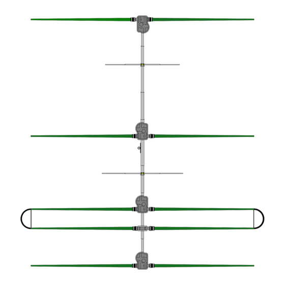
At a minimum, read the directions for each step before starting it. There will be a replacement in antenna parts if there is a 40/30m adder option, refer to that manual for those changes. Building your SteppIR™ is a straightforward process. It entails: Building the boom ... - Page 10 SteppIR Antennas - 4 Element Figure 1.5 7 Piece Boom Foward Drawing 1 shows the layout of the boom for assem- bly. Note that the lengths shown for each boom piece are overall lengths, the actual finished length of Reflrctor Mast the boom will be 32 feet.
- Page 11 SteppIR Antennas - 4 Element Locate and position the seven sections of boom tubing, and the respective fasteners. Figure 2 Rub a thin film of connector protector around the circumference of all male boom pieces BEFORE sliding the female sections over them (Figure 2). Also, do not twist the aluminum tubing excessively as that can cause binding.
- Page 12 SteppIR Antennas - 4 Element Locate: Two boom-to-mast plates (Figure 5) One 3/8 x 4” fully threaded bolt (EZeye™ bolt) Three 3/8 x 16x Nylok nut Two 3/8 flat washer Four 2” U-bolts with saddles & Nylok nuts ...
- Page 13 SteppIR Antennas - 4 Element...
- Page 14 SteppIR Antennas - 4 Element CONNECTING THE CONTROL CABLE TO THE D25 SPLICE...
- Page 15 SteppIR Antennas - 4 Element...
- Page 16 SteppIR Antennas - 4 Element...
- Page 17 SteppIR Antennas - 4 Element Proper EHU orientation is critical to operation of the antenna. Make sure they are installed on top of the element-to-boom brackets exactly as shown in Drawing 3 (looking down on the boom). Drawing 3 Refer to Figures 13, 14 and 15. Attach each EHU in place using eight #10-32 x 3/4” Phillips machine screws, flat washers and Nylok nuts.
- Page 18 (8 pairs of wires, each pair with one colored wire and one black wire) going to the shack is connected. Warning: Do NOT connect the 16 conductor cable to the SteppIR™ controller until instructed to do Carefully review Figures 17 and Drawing 4 before proceeding. First complete the reflector, direc-...
- Page 19 SteppIR Antennas - 4 Element NOTE - It is strongly recommended that you run the “Test Motor” function (Ref the Operators Manual) at this point to insure that all your wiring is correct and the element housing units are operating correctly.
- Page 20 SteppIR Antennas - 4 Element NOTE: If you are upgrading to a 4 element from a SteppIR™ 3 element Yagi, you will need to use the included 35 foot roll of 4 conductor cable to extend the control cable on each antenna housing to accommodate the longer boom length.
- Page 21 SteppIR Antennas - 4 Element Prepare the Fiberglass Element Support Tubes (standard poles) Note: If you have ordered the optional 40m - 30m Dipole Kit you need to refer to the section on preparing the poles (ESTs) in that specific manual. The 4 special poles for this option have some differences from the standard poles.
- Page 22 SteppIR Antennas - 4 Element Heat shrink tube instruction sheet On all elements we now include double wall polyolefin heat shrink, part number #03630. Each tele- scoping pole uses 3 pieces of the 1.5” x 3” long heat shrink, which forms an adhesive bond that is heat activated.
- Page 23 SteppIR Antennas - 4 Element 70-1007-01 FOAM PLUG ASSEMBLY Each 20m-6m element tip requires a breathable foam plug to be inserted onto the tip end of it so that the element is allowed to vent, but not let any non-liquid enter into the antenna. The foam plug assembly is NOT required for 40/30 elements.
- Page 24 SteppIR Antennas - 4 Element Attach the Fiberglass Telescoping Poles to the Element Housing Units The butt ends of the green fiberglass telescoping poles may vary slightly in outside diameter. Some of them may have been sanded, while others were not. The colors at the ends will be either natural, or black. The difference in colors has no affect on performance.
- Page 25 SteppIR Antennas - 4 Element 3. Insert the butt end of that FTP into one of the EST’s on an EHU, as shown in Figure 29. It is very important to ensure that the butt end of the EST firmly bottoms out inside the EST. Then push the quick disconnect boot firmly onto the EST until the hose clamp is past the aluminum ring and will clamp down onto the fiberglass telescoping pole (FTP).
- Page 26 SteppIR Antennas - 4 Element Note: Verify that the long element measures 110.5” and the short element measures 104.5”. Securely fasten the pieces together with the 6-32x3/4” machine screws and Nylok nuts and install the U- bolt on the center bracket as shown in Picture 32.5.
- Page 27 SteppIR Antennas - 4 Element Attach the cable clips to the Phillystran, with the first one as close to the end of the thimble as possible, so the cable will be “locked” in, and the next three approximately 1” apart (Figure 35). Figure 35.6 is a sample cable made up for the picture only to show what a finished cable will look like.
-
Page 28: Steppir Performance
It is this ability to move the performance peak that makes the SteppIR actually outperform a mono-bander over an entire band – even when the boom length isn’t what is classically considered "ideal". Bear in mind that a Yagi rarely has maximum gain and maximum front to back at the same time, so it is always a compromise between gain and front to back. - Page 29 Balun / Matching System The SteppIR has a matching system that is included in all Yagi antennas (a balun is available as an op- tion on the dipole). Our antenna designs are all close to 22 ohms at all frequencies, so we needed a broadband matching system that would transform 22 ohm to 50 ohm.
- Page 30 Yagi Gain / Front to Back Modeling SteppIR antenna designs are all close to 22 ohms at all frequencies, so we needed a broadband match- ing system. We found an excellent one designed by Jerry Sevick, that is described in his book “Building and Using Baluns and Ununs”.
- Page 31 SteppIR Antennas - 4 Element SteppIR Antennas - 3 Element SteppIR Options 40m - 30m Dipole (loop) “Y” Cable Transceiver Interface cable (Rig Specific) 6m Passive Element ...
- Page 32 SteppIR Antennas - 4 Element Voltage Suppressor & RF Bypass Unit ( 16 Conductor) * Connector Junction Box Element Expansion Kit Dipole 2 Element 2 Element 3 Element 3 Element 4 Element...
- Page 33 SteppIR will pay for standard shipping back to the buyer. The manufacturer assumes no further liability beyond repair or re-...
- Page 34 SteppIR Antennas - 4 Element...
- Page 36 2112 116TH AVE NE SUITE 1-5, BELLEVUE WA, 98004 WWW.STEPPIR.COM TEL: (425)-453-1910 FAX: (425)-462-4415...
Need help?
Do you have a question about the 4 Element Yagi and is the answer not in the manual?
Questions and answers