
Related Manuals for SteppIR BigIR


Summary of Contents for SteppIR BigIR
- Page 1 BigIR Antenna Assembly Manual REV 5.24 10/23/2023 13406 SE 32nd St. Bellevue, WA 98005 | consumer.steppir.com | 425.453.1910 | sales@steppir.com...
-
Page 2: Table Of Contents
Section 6: Mounting the BigIR 35-36 Counterpoise/Radial system overview - Ground mounted or elevated? 37-38 PTT lockout Tuning Relay (included) Optional 1:1 Balun Optional voltage/surge suppressor How to tune your vertical (Mandatory) 42-44 Product warranty claim Tech Support: consumer.steppir.com/support | 425.453.1910 | support@steppir.com... -
Page 3: Steppir-Why Compromise
STEPPIR—WHY COMPROMISE? The SteppIR antenna was originally conceived to solve the problem of covering the six ham bands (20m, 17m, 15m, 12m, 10m and 6m) on one tower without the performance sacrifices caused by interaction be- tween all of the required antennas. -
Page 4: Preparing For Assembly
“off” on your controller, there is still a very small amount of power feeding to the stepper motors, to effectively “lock” them in place. This leads to less need for calibration of the antenna. Tech Support: consumer.steppir.com/support | 425.453.1910 | support@steppir.com... -
Page 5: Antenna Specifications
Adjustable elements Power rating 3.0 kW (1500W limit on 60/80m bands) Feed points Frequency coverage 3.4-55 MHz with loading coil, 7.0- 54MHz without Control cable 2 x 4 conductor with coil, 1x without Tech Support: consumer.steppir.com/support | 425.453.1910 | support@steppir.com... -
Page 6: Antenna Overview
ANTENNA OVERVIEW The BigIR is a vertical antenna that can be adjusted for resonance on the 40, 30, 20, 17, 15, 12, 10 and 6 meter ham bands, including frequencies in between. With the addition of the 80 meter coil accessory, the BigIR/80 will also provide coverage on 80 and 60 meters, including frequencies in between. -
Page 7: Parts Checklist
10-1013-02 Telescoping Pole, 18 foot 4 section BigIR EST extension with aluminum coupler - Lower 70-2019-01 BigIR EST extension with aluminum coupler and ring - Upper 70-2020-01 CPVC Liner for BigIR, 89"x3/4", with coupler 70-2021-01 CPVC Liner for BigIR, 89" x 3/4", w/o coupler... - Page 8 72-0044-04 or –05 Kit, BigIR Mark IV Hardware/Heat Shrink DESCRIPTION ✓ PART # QUICK DISCONNECT, 1-1/2" to 1-1/4", Fernco 60-1006-22 Hose Clamp, 1.16" to 2" ID, Used for BigIR, S/S 60-6000-20 10-1104-11 O-Ring, 1-3/4" x 2", EP DM 72-0009-03 Kit, Glue 10-1029-01 Connector Protector Cat, 0.14 oz, (silicon goop for terminals)
- Page 9 PARTS CHECKLIST PARTS CHECKLIST 72-0044-11 Kit, BigIR EHU Wind Reinforcing Kit/ Mark IV Hardware ✓ PART # DESCRIPTION Coax Seal, 12' x 1/2" 8” 09-1022 10-1021-54 Reinforcing Plate, for High wind kit EHU, 10-7/16" x 4-1/4" x 1/4" Anti-seize single packets, TMP-1 10-1028-01 Saddle, 1-3/4"...
- Page 10 60-0027 Bolt, 1/4"-20 x 1", S/S 60-0030 Nut, 1/4"-20, Nylock, S/S Quick Link, 3/16", S/S 60-0094 06021 80M Base loading Coil for the BigIR PART # DESCRIPTION ✓ 70-2101-01 Coil, 80m, BigIR 72-0044-20 Kit, BigIR Mark IV 80m Coil Hardware...
-
Page 11: Vertical Mounting Post Overview
1/4” wall. One end of the tube has been turned down to an outer diameter of 1.48” such that it will fit into the EHU assembly. Note that most 1.5” OD tubes/pipes will not fit in the SteppIR EHU due to the tight fiberglass tolerances, so it is recommended to use ours. - Page 12 Elevated mounting: For those who are experienced with tuning elevated vertical antenna radial systems (more info on pg. 37-38) it is possible to mount the BigIR with its base raised off of the ground. This can be done in a number of ways, however it is crucial that the vertical mounting post (if conductive) is electri- cally disconnected from the radials/counterpoise to prevent arcing.
-
Page 13: Ehu Overview
EHU OVERVIEW Figure 1.05 provides an overview of a SteppIR EHU (the specific model shown is a 20m driven). Element Support Tube (EST) EHU terminal header Sprocket/Stepper motor Platen Balun (yagi driven EHU only) Spool with copper tape SO-239 (driven EHU only) Control cable routing tray Figure 1.05... -
Page 14: Section 1: Wiring And Ehu/Coil Assembly
Figure 1.12 shows a blue line crossing out the text in question. The orange circle shows the correct wiring sequence. 0.25 1.5” Figure 1.10 Figure 1.11 Figure 1.12 4 Pin Header Wiring Sequence BLACK GREEN WHITE Figure 1.13 Tech Support: consumer.steppir.com/support | 425.453.1910 | support@steppir.com... - Page 15 EHU. Repeat this process to the remaining areas of the wire tray as shown in figure 1.19. 12. When finished, the EHU will be secured to the high wind reinforcing kit and optional loading coil. Figure 1.15 Figure 1.16 Figure 1.17 Figure 1.18 Figure 1.19 Tech Support: consumer.steppir.com/support | 425.453.1910 | support@steppir.com...
- Page 16 Do not install if using 80m coil Use anti-seize on all SS hardware! Part Number Description EHU, BigIR (with control cable & coax seal) 10-1501-22 Cover for EHU, no drain hole 10-1502-12 EHU Gasket 60-0017 Pan Screw, 10-32 x 3/4”...
- Page 17 Washer, 5/16", Flat, S/S 10-1613-11 AL Spacer, 1/4" X 5/16" ID X 3/4" OD 60-0046 Nut, 5/16" -18, Nylock, S/S 60-0071 Screw, 10-32 x 1", Panhead, Phillips, S/S 60-0018 Washer, 10-32, Flat 60-0019 Nut, 10-32, Nylock Tech Support: consumer.steppir.com/support | 425.453.1910 | support@steppir.com...
- Page 18 Use anti-seize on Do not install if using loading coil all SS hardware! Part Number Description Plastic Saddle, 1.75" medium - BigIR/ 10-1611-31 StealthIR 10-1611-51 Plastic Saddle, 2" - BigIR/StealthIR 10-1021-54 Reinforcing Plate, for High wind kit EHU...
- Page 19 Part Number Description 60-0095 Screw, 10-32 x 2", Panhead, Phillips, S/S 60-1004-01 Spacer, 1/2", Nylon 10-1613-11 AL Spacer, 1/4" X 5/16" ID X 3/4" OD 60-0018 Washer, 10-32, Flat 60-0019 Nut, 10-32, Nylock Tech Support: consumer.steppir.com/support | 425.453.1910 | support@steppir.com...
- Page 20 Section 1.3 (continued): 80m Base Coil Installation (skip if 80m coil is not pur- chased) EHU ground lug Keep all radials/ cables clear of high voltage cable! Use a dielectric grease on the center conductor and threads, and coax seal for the exterior of the connection. Tech Support: consumer.steppir.com/support | 425.453.1910 | support@steppir.com...
- Page 21 5. A small piece of coax seal should be used to seal the outer insulation of the 4 conductor control cable as well (figure 1.45). Figure 1.41 Figure 1.42 Figure 1.43 Figure 1.44 Figure 1.45 Figure 1.46 Tech Support: consumer.steppir.com/support | 425.453.1910 | support@steppir.com...
- Page 22 Once the antenna is mounted and your radial set- up is prepared, the radials can then be attached to the ground lug on the coil, and coax seal can be applied to all external electrical connections on the EHU/coil. Tech Support: consumer.steppir.com/support | 425.453.1910 | support@steppir.com...
- Page 23 For first time setups it is common for this to be only partially installed, resulting in fault codes on the controller. 0.25” 2.75” Figure 1.20 Figure 1.30 Figure 1.31 Tech Support: consumer.steppir.com/support | 425.453.1910 | support@steppir.com...
- Page 24 *Ensure that the shield wire for both the EHU and loading coil connect to the “G” terminal on the DB25 connector, and trim them at the EHU/ coil so they are not connected to anything. Shield Coil Tech Support: consumer.steppir.com/support | 425.453.1910 | support@steppir.com...
-
Page 25: Section 2: Ehu/Coil Wiring Tests
For example: if you don’t have the loading coil, meas- ure the pin pairs associated with the BigIR EHU only. You should read between about 15 ohms to 30 ohms depending on cable length between the pins listed below. Record your results in the “Results” column. (100’... - Page 26 EHU/COIL WIRING TESTS Section 2.2: BigIR Open Circuit Test (mandatory) Step 4: Next make sure there is an open circuit between the following pins. Record your results in the “Results” column. (Any reading < 100 K ohms is bad) Open Circuit Test Table...
- Page 27 9. If the tape extends properly, press the retract button to retract the elements and proceed to the next as- sembly step. Figure 2.31 3.75” 2.95” OptimizIR (extended) SDA100 (inset) Tech Support: consumer.steppir.com/support | 425.453.1910 | support@steppir.com...
-
Page 28: Section 3: Prepare The Telescoping Pole
7. The heat shrink will want to slide as it is heated so wear gloves and reposition the heat shrink to keep it centered on the joint as needed. Caution: The heat shrink will be HOT, wear insulated gloves! 1.1”x6” 1.5”x6” 1.5”x6” Tech Support: consumer.steppir.com/support | 425.453.1910 | support@steppir.com... - Page 29 • Insert the plastic housing onto the telescoping pole tip as shown in figure 3.2. Be sure that the telescop- ing pole bottoms out on the vent tube. Figure. 3.2 Tech Support: consumer.steppir.com/support | 425.453.1910 | support@steppir.com...
-
Page 30: Section 4: Prepare The Cpvc Liner
CPVC glue. • Be sure to save some glue for later, as this will be used to install the CPVC liner onto the BigIR EHU dur- ing final assembly. Tech Support: consumer.steppir.com/support | 425.453.1910 | support@steppir.com... -
Page 31: Section 5: Prepare The Est Extension Assembly
Polyolefin Heat Shrink 2.05” x 4” 10-1104-11 O-ring, 1-3/4” x 2” 60-6000-20 Hose Clamp, 1.16” to 2“ ID, SS 60-1006-22 Quick Disconnect, 1-1/2” to 1-1/4” 10-1105-11 Vertical Pole Rain Cap 72-0046-01 BigIR Guy Kit Tech Support: consumer.steppir.com/support | 425.453.1910 | support@steppir.com... - Page 32 From the pole box, identify the upper and lower EST extensions (PN 70-2019-01 & 70-2020-01 respec- tively) and set on a clean and dry surface. • From the BigIR Mark IV Hardware/Heat Shrink kit (PN 72-0044-04) remove the following components: Part Number Description 10-1104-11 O-Ring, 1-3/4"...
- Page 33 EST extension assembly. Note: press the hose clamp firmly to be butted against the O-ring/coupler. Figure 5.6 • The completed assembly should look like figure 5.7 below: Figure 5.7 Tech Support: consumer.steppir.com/support | 425.453.1910 | support@steppir.com...
- Page 34 At this point the CPVC liner assembly can be slid into the EST extension assembly, and the telescoping fiberglass pole assembly can be affixed to the top of the upper EST extension assembly with the use of the provided quick disconnect boot (PN 60-1006-22). See pg. 35-36 for additional reference. Tech Support: consumer.steppir.com/support | 425.453.1910 | support@steppir.com...
-
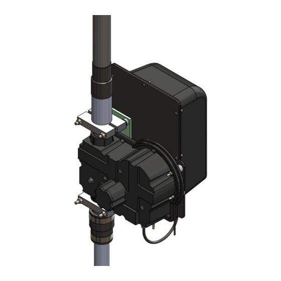
Page 35: Section 6: Mounting The Bigir
Work quickly as the glue will dry quickly and become less effective. 2) Insert the EST extension assembly’s aluminum coupler over the BigIR EHUs EST. Once it is fully seated, place the 2” aluminum saddles (or plastic) evenly onto the aluminum coupler and tighten the hardware until secure. - Page 36 EHU ground lug Note: If using radial distribution plate, be sure to use a thick braided or solid ground strap between the EHU/Coil ground lug and radial plate (coil ground lug shown on pg. 22). Tech Support: consumer.steppir.com/support | 425.453.1910 | support@steppir.com...
-
Page 37: Counterpoise/Radial System Overview - Ground Mounted Or Elevated
Elevating lowers the impedance so radials results in much lower losses even on 80m, so 5 might need up to a 30° downward slope to get a feet is just fine for 80m good match Tech Support: consumer.steppir.com/support | 425.453.1910 | support@steppir.com... - Page 38 0.48 0.54 Radil Length in Wave length Radial length in wavelength For more detailed information on ground mounted and elevated mounted radial setups, please read our complete white paper on radials: https://consumer.steppir.com/wp-content/uploads/2018/11/Radial-Systems-for-Elevated-and-Ground -Mounted-Antennas-2.2-12_2018.pdf Tech Support: consumer.steppir.com/support | 425.453.1910 | support@steppir.com...
-
Page 39: Ptt Lockout Tuning Relay (Included)
PTT LOCKOUT TUNING RELAY (INCLUDED) To prevent application of unintended, excessive RF power while the SteppIR antenna is tuning, the OptimizIR controller provides an isolated pair of contacts from a 3.5 mm stereo jack to interrupt the PTT relay signal to a linear amplifier. -
Page 40: Optional 1:1 Balun
There are numerous options for mounting the balun—by far the most popular is to mount the balun on an ad- jacent post or similar structure via the 2 mounting holes molded in its housing. There are 2 locations SteppIR recommends installing the 1:1 balun. If you have one balun then install it just outside of the radial field. If you have 2 baluns available to you then do both locations shown in figure 8.1. -
Page 41: Optional Voltage/Surge Suppressor
8. We recommend sealing up the connections by either using silicone tape or electrical tape to wrap the entire Voltage/Surge Suppressor and cable connections so that they do not corrode from moisture. Figure 9.2 Figure 9.1 Tech Support: consumer.steppir.com/support | 425.453.1910 | support@steppir.com... -
Page 42: How To Tune Your Vertical (Mandatory)
SteppIR antenna tunes are broken up into “segments” which we use to create an ideal antenna at a specific frequency. Each segment consists of a frequency, element lengths, coil switch command, and some miscellaneous display settings like gain, F/R, and beam width. - Page 43 9900 10100 6900 7150 5200 5350 3750 3875 3600 3675 3500 3550 3400 3450 Please refer to the create/modify section of the controller manual for more information on tuning SDA 100 Manual: https://consumer.steppir.com/wp-content/uploads/2020/10/SDA100-Operators-Guide-MUSTANG.pdf Tech Support: consumer.steppir.com/support | 425.453.1910 | support@steppir.com...
- Page 44 5200 5250 4100 4150 4000 4050 3750 3875 3600 3675 3500 3550 3400 3450 Please refer to the create/modify section of the controller manual for more information on tuning OptimizIR Manual: https://consumer.steppir.com/wp-content/uploads/2018/05/SDA-2000-OptimizIR-Manual-Version-1_4-April-17 -2018.pdf Tech Support: consumer.steppir.com/support | 425.453.1910 | support@steppir.com...
-
Page 45: Product Warranty Claim
SteppIR Communication System’s responsibility is strictly limited to repair or replacement of defective components, at SteppIR’s discretion. SteppIR will not be held responsible for any installation or removal costs, costs of any ancillary equipment damage or any other costs incurred as a result of the failure of our products. - Page 46 Tech Support: consumer.steppir.com/support | 425.453.1910 | support@steppir.com...
Need help?
Do you have a question about the BigIR and is the answer not in the manual?
Questions and answers