SteppIR 3 Element Yagi Instruction Manual
Hide thumbs
Also See for 3 Element Yagi:
- Instruction manual (34 pages) ,
- Troubleshooting manual (5 pages) ,
- Instruction manual (42 pages)

Related Manuals for SteppIR 3 Element Yagi


Summary of Contents for SteppIR 3 Element Yagi
- Page 1 3 Element Yagi Instruction Manual Revision 3.81 05/22/2023 13406 SE 32nd St, BELLEVUE WA, 98005 WWW.STEPPIR.COM TEL: (425)-453-1910...
- Page 2 SteppIR to be a commercially feasible product. The current and future SteppIR products should produce the most potent single tower antenna systems ever seen in Amateur Radio! We thank you for using our SteppIR antenna for your ham radio endeavors.
- Page 3 All of these methods have one thing in common–they significantly compromise performance. The SteppIR™ antenna system is our answer to the problem. Yagi antennas must be made a specific length to operate optimally on a given frequency.
- Page 4 Improper specification of an antenna or rotator to a tower can result in product failure, injury or death. SteppIR is not an expert on tower or rotator sizing and for this reason will never offer any recommendation – this specification process is meant for industry professionals such as a structural engineer, tower manufacturer or rotator manufac- turer.
- Page 5 14-19 Mounting the EHU’s to antenna boom 20-21 Preparation of the telescoping poles 22-30 Attach the poles to the EHU 6m passive element Element truss (40/30 Loop) 33-38 Attach the boom to the mast 39-41 SteppIR Performance Information 42-45 Warranty...
- Page 6 BILL OF MATERIALS— as shipped 00243-SPS 3 ELEMENT Qty Per Antenna Box (61” x 13” x 10”) 09-0001 Electrical tape 3/4" PVC MERCO 307 09-1025 conical grinding stone, 3/4", (ENCO) 10-1013-02 Telescoping Pole, 18 foot 4 section 10-1028-21 TM-1 Thread Magic Anti-seize sticks 10-1054-02 Truss Support, 30m/40m, 36"...
- Page 7 BILL OF MATERIALS (continued) 00243-SPS 3 ELEMENT Sweep Box (32” x 24” x 7”) 10-1153-01 Poly Sweeps (100psi) 10-1511-01 Sweep Diverter 10-1059-21 Polyolefin Heat Shrink 1.1” x 6” 10-1503-21 Fiberglass rod, 3/8" x 31-3/4" long, black 72-0008-11 Kit, 30/40m Return Hardware 72-0014-01 Kit, 2E/3E 6 m Hardware 72-0018-31...
- Page 8 BILL OF MATERIALS— KITS Item 72-0008-01 ELEMENT RETURN HARDWARE KIT Qty Per 09-0001 Electrical tape 3/4" PVC MERCO 307 10-1029-01 Connector Protector Cat, No CP-1, .14 oz, (silicon goop for terminals) 20-6020-01 Terminal Block, 1 position 60-0061 Screw, 10-32 7/8", Panhead, S/S 60-6000-40 Hose Clamp, 4.0", #56, S/S, (4 el term hosing clamp) 60-1009-01 Plug, 1-1/2", ABS Threaded, ADWVCOPJ 20-6020-08 Terminal Block, 8 position...
- Page 9 7. Do a complete inventory of every part, nut and bolt. Yes it takes time, but it also allows you to noti- fy SteppIR if anything is missing and allow time to get it to you before you start assembly of the antenna.
- Page 10 STAINLESS STEEL FASTENER INFORMATION From time to time, we get complaints from customers regarding galling of stainless steel fasteners. Thread galling seems to be Here is an excerpt from the Industrial Fastener Institute's Standards Book: the most prevalent with fasteners made of stainless steel, aluminum, titanium and other alloys which self-generate an oxide surface film for corrosion protection.
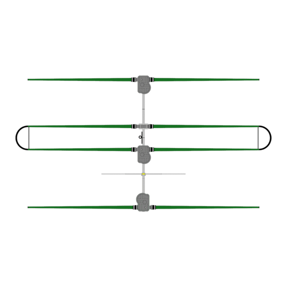
- Page 11 ANTENNA DIRECTION CONFIGURATION REVERSE DIRECTION FORWARD DIRECTION (Normal) (180 deg) 40m-6m Director 40m-6m Reflector Passive Element 40m-6m Driven 40m-6m Driven The driven element is a dipole when on 40 and 30 meters 40m-6m Reflector 40m-6m Director...
- Page 12 BOOM INSTALLATION The 3 element SteppIR Yagi boom consists of four sections of aluminum tubing that are 4 feet long x 1- 3/4” OD x 1/8” wall, along with three aluminum element mounting brackets as shown in Figure 1. The element mounting brackets are pre-installed at the factory.
- Page 13 BOOM INSTALLATION (continued) Connect the boom by sliding the respective sections together and align the pre-drilled holes (Figure 3 and 4). Refer to Figure 6 and figure 7 for correct configuration. It is advisable to apply a thin film of anti-zeize (included) or Naolox (not included) to the joints before mating them. Do not twist the aluminum excessively, as this can cause binding - the lubricant will help keep the two pieces from seizing together.
- Page 14 ELEMENT HOUSING UNIT (EHU) WIRING Figure 8 gives an overview of the inside of a SteppIR EHU. Wiring of each EHU will be covered in de- tail on the following pages. NEVER ATTEMPT ANY WIRING WHILE THE ELECTRONIC CONTROLLER IS CONNECTED TO THE CONTROL CABLE.
- Page 15 EHU WIRING (continued) Trim approximately 1.5 inches of the outer jacket of the control cable (4 wire). Remove the shield material, the support thread and cut the ground wire off as shown in figure 9. Attach electrical tape at the end of the trimmed control cable jacket so that there is no chance for a short.
- Page 16 EHU WIRING (continued) Check to be sure the terminal plug is firmly inserted into the terminal header. Lay the control cable wire inside the wire tray of the EHU as shown in figure 14. This trough acts as a strain relief so that the cable will not be pulled out of the EHU. It is a good idea to leave a small amount of slack between the plug and the point which the tray starts as shown in figure Using the coax seal and cut into 1 inch strips as shown in...
- Page 17 The DB25 Field replaces the standard connector with a convenient solder-less connection of the control cable to the SteppIR controller. Follow the steps below to connect it to your control cable. 1. Apply dielectric grease to the exposed copper portion of each wire.
- Page 18 25 PIN DSUB SPLICE INSTALLATION 25 PIN DSUB FIG. 23 FIELD SPLICE TERMINAL STRIPS (3) 12 WIRE CONTROL CABLE BLACK BROWN ORANGE YELLOW GREEN BLUE VIOLET GREY WHITE PINK ...
- Page 19 CONNECTOR JUNCTION BOX WIRING LAYOUT FIGURE 42 FIGURE 43...
- Page 20 MOUNTING THE EHU TO THE BOOM Attaching the EHU to the boom is a two step procedure. The first step involves attaching the lid and gas- ket with the three screws shown in figure 31. The second step is to attach the EHU to the element mount- ing plate on the boom with the remaining seven screws as shown in figure WARNING: When assembling the lid to the housing and the housing to the boom, make sure that the...
- Page 21 MOUNTING THE EHU TO THE BOOM Attach the antenna housing to the element-to-boom bracket Figure 33 shows the element boom bracket. Place the flat side of the element housing unit (EHU) on top of the element boom brackets (Figure 34). If the mounting holes for the element housing do not line up with the holes in the element bracket it may be necessary to loosen the two horizontal bolts that hold the element bracket to the boom .
- Page 22 PREPARING THE TELESCOPING POLES 1. Extend the telescoping poles (PN 10-1013-02) to full length by firmly locking each section of the pole in place. A good methodology is to position each half of the joint so that they are several inches apart (while still within each other), and then pull quickly and firmly.
- Page 23 ATTACHING SWEEPS AND DIVERTERS TO FIBERGLASS 8. Use the glue kit (PN 72-0009-03) from the glue/tape kit to attach the sweep diverters (PN 10-1511-01) to the tips of the fiberglass telescoping poles. ONLY APPLY GLUE TO THE FIBERGLASS. Slowly rotate the sweep diverter as you slide it onto the pole to let the glue cover the most surface area possible.
- Page 24 ATTACHING SWEEP COUPLERS TO SWEEP TUBES • Refer to figure 6.06 during the following steps for an overview of the assembly process. • Each of the sweep coupler halves (PN 10-1155-01) will have a notch in the mold on one side marked with silver sharpie.
- Page 25 MOUNTING THE FIBERGLASS SPREADERS 17. Mount the black fiberglass sweep spreaders (PN 10-1503-21) to the sweep couplers. There is a concave mounting area on each side of the plastic couplers. Position the fiberglass spreader so that the holes align with the clam shell couplers as shown in figure 6.10.
- Page 26 FINAL TIGHTENING 21. Finish tightening the four screws on the outside corners of the plastic coupler. Tighten evenly, in an automobile X type pattern as shown in figure 6.14. If you do not tighten evenly, you may break the fastener. Once the outsides are firmly tight, tighten the two screws that hold the fiberglass spreader in place.
- Page 27 ATTACH FOAM PLUGS TO NON LOOP ELEMENT TIPS Each 20m-6m telescoping pole tip requires a breathable foam plug to allow for venting of the EHU. The foam plug assembly (PN 70-1007-01) consists of a special UV resistant foam plug material, and a plastic housing as shown in figure 6.30.
- Page 28 ATTACH THE ELEMENTS TO THE EHU’s PREPARE THE CPVC INNER-GUIDE TUBE & DIVERTER CONE The 40/30 loops on the DB18E Yagi use a plastic tube and a diverter cone located inside the telescoping pole, to guide the copper strip out of the EHU. Note that the straight elements do not use this inner tube, only the 40/30 loops.
- Page 29 ATTACH THE ELEMENTS TO THE EHU’s (continued) SECURING THE ELEMENT SUPPORT TUBE (EST) TO THE EHU When the CPVC inner guide tubes are completed, they will need to be inserted into the telescoping poles and secured to each EHU. Figure 7.10 below gives an overview of this procedure, with detailed instructions following on the next page.
- Page 30 ATTACH FOAM PLUG HOUSINGS TO TELESCOPING POLES Each 20m-6m telescoping pole tip requires a breathable foam plug to allow for venting of the EHU. The foam plug assembly (PN 70-1007-01) consists of a special UV resistant foam plug material, and a plastic housing as shown in figure The foam plug is installed inside the plastic housing at the factory.
- Page 31 Attach the non-loop Fiberglass Element Support Tubes to the Element Housing Units The butt ends of the green fiberglass poles may very slightly in outside diameter. Some of them may have been sanded, while others were not. The colors at the ends will be either natural, or black. The difference in colors has no affect on performance.
- Page 32 6 Meter Passive Element The 6 meter passive element comes in 3 pieces. The main body with a 1/2” x 58” element section at- tached to it, and two 3/8” element sections (Figure 58). The overall length of the element is approxi- mately 112”...
- Page 33 ELEMENT TRUSS OVERVIEW...
- Page 34 ELEMENT TRUSS SUPPORT Check and inventory that you received all the parts for the 39 ft 40M/30M truss option. • Be sure to use anti-seize on all of the stainless steel fasteners in this step. Failure to do so will potentially •...
- Page 35 ELEMENT TRUSS SUPPORT CONT. 2. Attach each of the 4” stainless steel turnbuckles (PN 60-0083) using the 1/4” x 1-1/4” hex head bolt (PN 60-0110), two of the 5/16” stainless steel flat washers (PN 60-0033) and 1/4” Nylock nuts (PN 60-0030) as shown in figure 14.04 and figure 14.05.
- Page 36 ELEMENT TRUSS COUPLER 1. Each element truss coupler consists of 2 halves as shown in figure 2.01. The element truss couplers (PN 10-1510-01) are used for fastening the Dacron rope to the last section of the telescoping poles. Figure 2.12 on page 8 provides an expanded view of a truss element assembly. 2.
- Page 37 ELEMENT TRUSS COUPLER (CONTINUED) 4. The Dacron rope is provided in a single piece. You will need to trim the pieces to length as you proceed in installing each half-portion of the truss. Melt the end of the rope with a lighter as shown in figure 2.09 to insure it does not fray.
- Page 38 ELEMENT TRUSS SUPPORT (CONTINUED) 3. Loop 1/8” Dacron rope (PN 21-7001-01) around each thimble as shown in Figure 2.18. 4. Secure each rope length together with two 1/8” Wire Clips (PN 60-0157). There should be about 3” be- tween each clip as shown in Figure 2.19. Figure 2.18 Figure 2.19 5.
- Page 39 INSTALL THE MAST SADDLES QTY Part Number Description 10-1021-43 Mast Plate 10-1601-22 Saddle Clamp, 2” 60-0066 Hex Bolt, 5/16” x 4” 60-0046 Nylock Nut, 5/16 60-0017 Pan Screw, 10-32 x 3/4” 60-0112 Set Screw, 10-32 x 1/4”, Cup Point...
- Page 40 INSTALL THE FULLY THREADED BOLT KEY QTY Part Number Description 60-0085 Hex Bolt, 3/8” x 4”, Fully Threaded 60-0051 Lockwasher, 3/8”, Split 60-0049 Nut, 3/8” 60-0050 Nylock Nut, 3/8”...
- Page 41 HIGH WIND KIT • Remove the vertical 1/4-20 bolt from the #2 splice. • Drill out the hole with the included “N” (.320”) drill bit. • Use the exploded view drawing below to install the mast plate. • Adjust the two Nylock nuts on the EZ-Eye stud to make sure the boom is level. •...
- Page 42 It is this ability to move the performance peak that makes the SteppIR actually outperform a mono-bander over an entire band – even when the boom length isn’t what is classically considered "ideal". Bear in mind that a Yagi rarely has maximum gain and maximum front to back at the same time, so it is always a compromise between gain and front to back.
- Page 43 Balun / Matching System The SteppIR has a matching system that is included in the 2 element, 3 element, 4 element and MonstIR Yagi (a balun is available as an option on the dipole). Our antenna designs are all close to 22 ohms at all frequencies, so we needed a broadband matching system that would transform 22 ohm to 50 ohm.
- Page 44 Yagi Gain / Front to Back Modeling SteppIR antenna designs are all close to 22 ohms at all frequencies, so we needed a broadband match- ing system. We found an excellent one designed by Jerry Sevick, that is described in his book “Building and Using Baluns and Ununs”.
- Page 45 It is this ability to move the performance peak that makes the SteppIR actually outperform a mono-bander over an entire band – even when the boom length isn’t what is classically considered "ideal". Bear in mind that a Yagi rarely has maximum gain and maximum front to back at the same time, so it is always a compromise between gain and front to back.
- Page 46 Shipping instructions will be issued to the buyer for defective compo- nents, and shipping charges to the factory will be paid for by the buyer. SteppIR will pay for stand- ard shipping back to the buyer. The manufacturer assumes no further liability beyond repair or re- placement of the product.
- Page 47 13406 SE 32nd St, BELLEVUE WA, 98005 WWW.STEPPIR.COM TEL: (425)-453-1910...
Need help?
Do you have a question about the 3 Element Yagi and is the answer not in the manual?
Questions and answers