Table of Contents
Advertisement
DB18 Yagi
Assembly Manual
EA3PW
This assembly manual is intended to be
COLOR
printed in full
. If the manual is
printed in
black and
white, many im-
portant details could be lost.
REV 10.2
02/25/2014
Page 1
2112 116th Ave NE #1-5, Bellevue, WA 98004 Tel: 425.453.1910 email: sales@steppir.com
Tech Support: www.steppir.com/support Tel: 425.891.6134 support@steppir.com
Advertisement
Chapters
Table of Contents

Related Manuals for SteppIR DB18 Yagi


Summary of Contents for SteppIR DB18 Yagi
- Page 1 . If the manual is printed in black and white, many im- portant details could be lost. REV 10.2 02/25/2014 Page 1 2112 116th Ave NE #1-5, Bellevue, WA 98004 Tel: 425.453.1910 email: sales@steppir.com Tech Support: www.steppir.com/support Tel: 425.891.6134 support@steppir.com...
-
Page 2: Preamble
PREAMBLE DB18 Yagi Specifications DB18 Yagi w / 6m passive option Specifications DB18 Yagi Boom length 19 ft / 5.79 m Boom outside diameter 1.75 in—2 in / 4.45—5.08 cm Longest element 39 ft / 11.9 m Turning radius 21.58 ft / 6.57 m Weight 96 lb / 43.5 kg... -
Page 3: Table Of Contents
Attach the boom to the mast plate CHAPTER THREE—MAST PLATE AND TRUSS ASSEMBLY 27-39 Section 3.0: Element housing unit (EHU) placement EHU center-to-center spacing measurements Section 3.1: EHU wiring overview EHU wiring 30-31 Page 3 Tech Support: www.steppir.com/support Tel: 425.891.6134 support@steppir.com... - Page 4 CHAPTER FIVE—WIRING THE CONNECTOR JUNCTION BOX 44-53 Section 5.0: Mount the connector junction box onto boom Section 5.1: Wiring the connector junction box 45-47 Connecting the control cable from coax switch to junction box Page 4 Tech Support: www.steppir.com/support Tel: 425.891.6134 support@steppir.com...
- Page 5 61-62 CHAPTER EIGHT—OPTIONAL 40/30 END ELEMENT TRUSS KIT 63-66 Section 8.0: Installing the truss support mast Section 8.1: Attach the truss couplers Section 8.2: Routing the Dacron truss cord 65-66 Page 5 Tech Support: www.steppir.com/support Tel: 425.891.6134 support@steppir.com...
- Page 6 Secure the cables to the boom Section 11.1: Mount the DB18 onto the tower mast 74-75 CHAPTER TWELVE—TROUBLESHOOTING TIPS 76-78 Section 12.0: Troubleshooting tips 76-77 SteppIR product warranty Contact information Page 6 Tech Support: www.steppir.com/support Tel: 425.891.6134 support@steppir.com...
- Page 7 3. Do a complete inventory of every part, nut and bolt. Yes it takes time, but it also allows you to notify SteppIR if anything is missing and allow time to get it to you before you start assembly of the antenna.
- Page 8 PREAMBLE OK - - - NOW WHAT? (continued) (Sage advise from Jim Streible, K4DLI—SteppIR Technical Support Guru) Your Antenna Has Arrived! What is the first thing to do? (continued) 5. When you have finished working with the controller be sure the display indicates “Elements Home”...
- Page 9 The items in blue represent options available for the DB18 Yagi—you will need to check these items off only if you purchased them. Part # Description...
- Page 10 16 pin voltage suppressor 40/30 Loop Element Truss Kit OPTION 72-0018-31 Loop element truss kit 10-1054-02 40/30 truss support arm Boom Truss OPTION 72-0043-01 Boom truss kit 10-1618-11 Boom support mast Page 10 Tech Support: www.steppir.com/support Tel: 425.891.6134 support@steppir.com...
- Page 11 1/4” Stainless steel washer 60-0037-21 5/16” x 4” Eyebolt S/S 60-0046 5/16” Nylock nut 60-0030 1/4” - 20 Nylock nut 60-0103 3” x 5/16” Hex head bolt 60-0033 5/16” Flat washer Page 11 Tech Support: www.steppir.com/support Tel: 425.891.6134 support@steppir.com...
- Page 12 10-32 X 3/4” Stainless steel machine screw 60-0018 # 10 SS washer 60-0019 10-32 Nylock nut 60-0046 5/16” Nylock nuts 60-0065 5/16” X 3-1/2” Stainless steel hex head bolt 10-1601-22 2” Aluminum saddle half Page 12 Tech Support: www.steppir.com/support Tel: 425.891.6134 support@steppir.com...
- Page 13 (use one set screw per pair of saddles) Glue, Tape & Anti-Seize Kit 72-0041-01 PART NUMBER DESCRIPTION 72-0009-03 Glue kit 09-0001 66’ PVC electrical tape 10-1028-01 Anti-Seize 10-1509-02 Diverter cone Page 13 Tech Support: www.steppir.com/support Tel: 425.891.6134 support@steppir.com...
- Page 14 03122 3 ft length 4 conductor control *This kit is not in a bag. The kit consists of the jumpers and the control cable, wrapped together for ship- ping purposes. Page 14 Tech Support: www.steppir.com/support Tel: 425.891.6134 support@steppir.com...
- Page 15 PREAMBLE ASSEMBLY KITS- BILL OF MATERIALS (OPTIONAL ITEMS) END TRUSS KIT 72-0018-01 (Quantities below are for one complete element truss kit—there are two truss kits included for a DB18 Yagi.) PART NUMBER DESCRIPTION 10-1601-03 1 3/4” Aluminum saddle half...
- Page 16 5/16” Nylock Nut 60-0083 4” Stainless steel turnbuckle 60-0093 5/16” x 2-3/4” Hex head bolt 60-0033 5/16 Flat washer 12 FT 60-0035-00 Phillystran 1200i 10-1618-11 1-3/4” x 30” Boom Truss Mast Page 16 Tech Support: www.steppir.com/support Tel: 425.891.6134 support@steppir.com...
- Page 17 When the power is “off” on your controller, there is still a very small amount of power feeding to the stepper motors, to effectively “lock” them in place. This leads to less need for calibration of the antenna. Page 17 Tech Support: www.steppir.com/support Tel: 425.891.6134 support@steppir.com...
-
Page 18: Antenna Configuration Guide
PREAMBLE ANTENNA CONFIGURATION GUIDE The DB18 Yagi antenna uses loop elements for 30m and 40M performance. The loop elements used for 40m and 30m are 40% shorter than a full size element, with very little sacrifice in performance (-0.3dB). The DB18 uses an integral coax switch to select which one of the three elements are driven to give equal performance in forward and reverse directions. -
Page 19: Preamble
You can be assured that the stainless steel fasteners we provide with our products are manufactured of very high quality. Page 19 Tech Support: www.steppir.com/support Tel: 425.891.6134 support@steppir.com... -
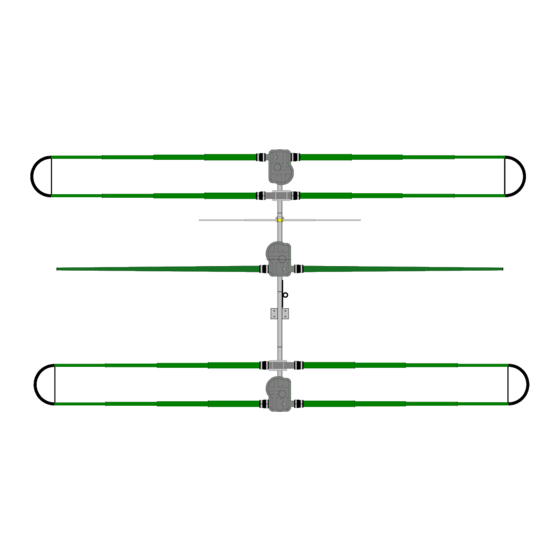
Page 20: Boom Layout
QTY 1: 60-0033 QTY 2: 60-0030 QTY 2: 60-0030 1/4” Nylock nut 5/16” Nylock nut 5/16” Flat washer 1/4” Nylock nut 1/4” Nylock nut (place between eye- bolt and aluminum tube) Page 20 Tech Support: www.steppir.com/support Tel: 425.891.6134 support@steppir.com... -
Page 21: Boom Bolt Detail
Always use anti-seize on stainless steel fasteners FIG. 1.03 5/16” Boom bolt configuration No Washers QTY 1: 60-0103 5/16” Hex head bolt QTY 2: 60-0033 5/16” Flat washers QTY 1: 60-0046 5/16” Nylock nut Page 21 Tech Support: www.steppir.com/support Tel: 425.891.6134 support@steppir.com... -
Page 22: Connecting The Ez-Eyebolt To The Boom
5/16”x3” Hex head bolt 60-0033 5/16” Flat washer 60-0046 5/16” Nylock nut 10-1203-01 1-3/4” x 12” Boom center-splice 60-0029 1/4” x 3” Hex head bolt 60-0041 1/4” Flat washer 60-0030 1/4” Nylock nut Page 22 Tech Support: www.steppir.com/support Tel: 425.891.6134 support@steppir.com... -
Page 23: Connecting The Ez-Eyebolt To The Boom
Align the eyebolt so that it is centered on the boom and tighten. Be sure that all the bolts are now tightened. Figure 1.15 shows the completed 2” boom piece with center-splice. FIG. 1.11 FIG. 1.12 FIG. 1.13 FIG. 1.14 FIG. 1.15 Page 23 Tech Support: www.steppir.com/support Tel: 425.891.6134 support@steppir.com... -
Page 24: Mast Plate-To-Boom Overview
3/8” Nylock nut 60-0034 3/8” Washer 60-0037 5/16” Stainless steel eyebolt 60-0114 5/16” x 3-3/4” Hex head bolt 60-0046 5/16” Nylock nut 10-1601-22 2” Aluminum saddle half 10-1610-22 11-1/2” Aluminum mast plate Page 24 Tech Support: www.steppir.com/support Tel: 425.891.6134 support@steppir.com... - Page 25 4 holes should be on the upper left side. FIG. 2.03 FIG. 2.02 FIG. 2.04 FIG. 2.06 FIG. 2.05 3/8 INCH Page 25 Tech Support: www.steppir.com/support Tel: 425.891.6134 support@steppir.com...
-
Page 26: Attach The Boom To The Mast Plate
Figure 2.16 shows the completed EZ-Eye assembly. FIG. 2.10 FIG. 2.12 FIG. 2.11 FIG. 2.13 FIG. 2.14 FIG. 2.15 FIG. 2.16 Page 26 Tech Support: www.steppir.com/support Tel: 425.891.6134 support@steppir.com... -
Page 27: Element Housing Unit (Ehu) Placement
ELEMENT HOUSING UNIT (EHU) PLACEMENT Each of the EHU’s on the DB18 Yagi are treated as a driven element, depending on what mode you are in or direction you are facing. The coax from the ham shack feeds into an integral coax switch, which seamlessly switches in and out the correct EHU behind the scenes. -
Page 28: Ehu Center-To-Center Spacing Measurements
MOUNTING THE EHU’S ON THE BOOM (continued) SECTION 3.0 EHU CENTER-TO-CENTER SPACING MEASUREMENTS It is critically important that the center-to-center spacing is correct when assembling your SteppIR Ya- gi. Use figure 3.02 for placement of each of the elements. Start from the left edge of the boom and measure from there. -
Page 29: Ehu Wiring Overview
ELEMENT HOUSING UNIT (EHU) WIRING OVERVIEW When wiring the EHU’s on the DB18 Yagi, it is important to know that there are two different types of EHU. The two end “loop” elements can function as either a passive element or a driven element, de- pending on what band or direction that antenna is in. -
Page 30: Ehu Wiring
6 Pin Header Wiring Sequence 4 Pin Header Wiring Sequence (EHU’s with Relays) (EHU’s without Relays) BLACK GREEN WHITE BLUE BROWN BLACK GREEN WHITE TERMINAL PLUG FIG. 3.14 TERMINAL HEADER Page 30 Tech Support: www.steppir.com/support Tel: 425.891.6134 support@steppir.com... -
Page 31: Ehu Wiring
Repeat wiring and coax seal preparation for each EHU. When finished, the EHU’s will be secured to the aluminum element mounting plates. This is covered in detail in the next chapter. FIG. 3.17 FIG. 3.15 FIG. 3.16 FIG. 3.18 FIG. 3.19 Page 31 Tech Support: www.steppir.com/support Tel: 425.891.6134 support@steppir.com... -
Page 32: Director Ehu & Return Tube Assembly Drawing
Director and Reflector EHU’s. Even though the installation of the boom truss does not take place until the DB18 Yagi is nearly completed, there are two truss attachment plates (PN 10-1607-01) that need to be installed while working in Chapter Three. - Page 33 EHU housing. Measure the proper distance from the edge of the boom to the center point of the element (5.0 inches) as (A tip from Adam Blackmer K7EDX, SteppIR operations manager— use the mold spline shown in figure 3.25.
-
Page 34: Return Tube Mounting—Director Ehu
If you did not purchase the boom truss op- tion, disregard this note. Figure 3.36 shows the completed director EHU and return bracket. FIG. 3.33 FIG. 3.31 FIG. 3.32 FIG. 3.30 FIG. 3.34 FIG. 3.35 FIG. 3.36 Page 34 Tech Support: www.steppir.com/support Tel: 425.891.6134 support@steppir.com... -
Page 35: Chapter Three Section
5/16”x3-1/2” Hex head bolt A (x10) 60-0046 5/16” Nylock nut B (x10) 70-3403-01 Driven Element EHU 10-1502-01 Element housing gasket 10-1015-11 Element mounting plate 10-1601-22 2” Aluminum saddle half C (x10) Page 35 Tech Support: www.steppir.com/support Tel: 425.891.6134 support@steppir.com... -
Page 36: Refer To The Center-To-Center Measurements In
Level the EHU as shown in figure 3.46 and tighten the aluminum saddles firmly. Figure 3.47 shows the completed Driven EHU. FIG. 3.41 FIG. 3.42 FIG. 3.43 FIG. 3.44 FIG. 3.45 FIG. 3.46 FIG. 3.47 Page 36 Tech Support: www.steppir.com/support Tel: 425.891.6134 support@steppir.com... -
Page 37: Reflector Ehu & Return Tube Assembly Drawing
Director and Reflector EHU’s. Even though the installation of the boom truss does not take place until the DB18 Yagi is nearly completed, there are two truss attachment plates (PN 10-1607-01) that need to be installed while working in Chapter Three. -
Page 38: (Pn 60-0019) As Shown In Figure
3.56 and tighten the aluminum saddles firmly. Figure 3.57 shows the com- pleted reflector EHU. FIG. 3.51 FIG. 3.52 FIG. 3.54 FIG. 3.53 FIG. 3.55 FIG. 3.56 FIG. 3.57 Page 38 Tech Support: www.steppir.com/support Tel: 425.891.6134 support@steppir.com... -
Page 39: As Shown In Figure
(one set screw per saddle pair). FIG. 3.62 FIG. 3.63 FIG. 3.60 FIG. 3.61 FIG. 3.64 FIG. 3.65 FIG. 3.66 Page 39 Tech Support: www.steppir.com/support Tel: 425.891.6134 support@steppir.com... -
Page 40: Fig. 4.01
MOUNTING THE COAX SWITCH HOUSING ASSEMBLY The DB18 Yagi offers high performance regardless of which band or direction the antenna is in. To do this, at any given time each EHU functions as a driven element. This is accomplished by using a single feed line, and switching in and out each driven element using a relay. -
Page 41: Section 4.1 Coax Switch Wiring
4.13. This will serve nicely as a strain relief. FIG. 4.10 FIG. 4.11 SHIELD BLACK DO NOT USE WHITE FIG. 4.12 FIG. 4.13 Page 41 Tech Support: www.steppir.com/support Tel: 425.891.6134 support@steppir.com... -
Page 42: Sealing & Securing The Coax Switch Housing
Figure 4.25 shows the completed coax switch housing. FIG. 4.20 FIG. 4.21 FIG. 4.22 FIG. 4.23 FIG. 4.24 FIG. 4.25 Page 42 Tech Support: www.steppir.com/support Tel: 425.891.6134 support@steppir.com... -
Page 43: Attach The Coax Jumpers And Feed Line
11 FT 6 IN OUT 3 COAX JUMPER TO DRIVEN EHU 4 FT FIG. 4.31 OUTPUT 3: DRIVEN; 4 FT OUTPUT 1: DIRECTOR; 8 FT OUTPUT 2: REFLECTOR; 11FT 6 IN INPUT: FEEDLINE Page 43 Tech Support: www.steppir.com/support Tel: 425.891.6134 support@steppir.com... -
Page 44: Mount The Connector Junction Box Onto Boom
Figure 5.05 shows the two #10 machine screws. Follow the instruc- tions in Chapter Eleven and then continue with Chapter Five. FIG. 5.02 FIG. 5.01 FIG. 5.04 FIG. 5.03 FIG. 5.05 Page 44 Tech Support: www.steppir.com/support Tel: 425.891.6134 support@steppir.com... - Page 45 NOT USED. COAX SWITCH 4 wire control cable; the green wire needs to be trimmed and HOUSING taped; R2 is NOT USED. 3 total wires used, plus shield wire. Page 45 Tech Support: www.steppir.com/support Tel: 425.891.6134 support@steppir.com...
- Page 46 W I R E C U T O U T S 4 wire control cable key 6 wire control cable key Coax switch wiring key SHIELD BLACK WHITE NOT USED Page 46 Tech Support: www.steppir.com/support Tel: 425.891.6134 support@steppir.com...
- Page 47 NOT USED NOT USED NOT USED NOT USED WHITE WITH RED STRIPE WHITE WITH BLACK STRIPE WHITE WITH GREEN STRIPE NOT USED Page 47 Tech Support: www.steppir.com/support Tel: 425.891.6134 support@steppir.com...
- Page 48 Be sure to trim the green wire on each end of the con- trol cable and tape over it to avoid potential electrical shorts. Page 48 Tech Support: www.steppir.com/support Tel: 425.891.6134 support@steppir.com...
- Page 49 CONNECTING CONTROL CABLE TO dSUB FIELD SPLICE The DB25 control cable splice allows for much more convenient connection of control cable to the SteppIR controller. By utilizing this connector splice, there is no need to cut the DB25 connector off and re-solder when running cable through conduit.
- Page 50 For the 25 pin connector installation, you would solder the ground wire to the case of the 25 pin connector and then put the backshell on. Page 50 Tech Support: www.steppir.com/support Tel: 425.891.6134 support@steppir.com...
-
Page 51: Wiring Test
11. When the controller indicates it is no longer trying to move the elements (the LED labeled “Tuning” will stop flashing) RECONNECT the control cable again. 12. Set your ohm meter to a low ohms scale (around 200 ohms or so). Page 51 Tech Support: www.steppir.com/support Tel: 425.891.6134 support@steppir.com... - Page 52 16. If any of these tests fail, Stop, Push Retract, Disconnect the controller cable and check your wiring and correct any mistakes. Then restart the test procedure at the beginning. 17. If all the tests results are good from step 15, DISCONNECT the control cable. Page 52 Tech Support: www.steppir.com/support Tel: 425.891.6134 support@steppir.com...
-
Page 53: Wiring Test
27. Push “POWER” and the controller will now turn off. DISCONNECT the control cable. 26. This concludes the tests and verifies the antenna is wired correctly and that all of the relays are switching correctly. Page 53 Tech Support: www.steppir.com/support Tel: 425.891.6134 support@steppir.com... - Page 54 Each line needs to change in color to ensure even adhesion temperatures . FIG. 6.01 TRIM THE TIP OF EACH POLE FOR AN OVERALL LENGTH OF 212.75 INCHES FIG. 6.02 FIG. 6.03 FIG. 6.04 FIG. 6.06 FIG. 6.05 FIG. 6.07 Page 54 Tech Support: www.steppir.com/support Tel: 425.891.6134 support@steppir.com...
- Page 55 – it should be fine from the factory but the OD of poles varies slightly, so if there is overlap, make sure you trim the tape so there is a gap, as shown in figure 6.08, Step FIG. 6.08 Page 55 Tech Support: www.steppir.com/support Tel: 425.891.6134 support@steppir.com...
- Page 56 These screws will be completely tightened later, tightening to this point provides a framework for the ensuing steps. FIG. 6.10 FIG. 6.11 Figure 1.07 FIG. 6.12 0.25” GAP Page 56 Tech Support: www.steppir.com/support Tel: 425.891.6134 support@steppir.com...
- Page 57 Tighten the Nylock nuts firmly. Be sure to use anti-seize on these screws or they very likely will gall and have to be replaced. FIG. 6.14 FIG. 6.15 FIG. 6.13 FIG. 6.16 Page 57 Tech Support: www.steppir.com/support Tel: 425.891.6134 support@steppir.com...
-
Page 58: Attach The Fiberglass Telescoping Poles To The Sweeps
When completely tightened, the sweep coupler halves should touch or almost touch. Similar to figure 6.23. Figure 6.16 shows a completed sweep. Repeat the same steps for the remaining sweeps. FIG. 6.21 FIG. 6.22 FIG. 6.20 FIG. 6.23 FIG. 6.24 FIG. 6.25 Page 58 Tech Support: www.steppir.com/support Tel: 425.891.6134 support@steppir.com... -
Page 59: Chapter Six Section
6.32. Be sure that the plastic housing bottoms out on the pole tip, as shown in figure 6.33. Repeat for the other telescoping pole tip. FIG. 6.30 FIG. 6.31 FIG. 6.32 FIG. 6.33 Page 59 Tech Support: www.steppir.com/support Tel: 425.891.6134 support@steppir.com... -
Page 60: Fig. 7.07
PREPARE THE CPVC INNER-GUIDE TUBE & DIVERTER CONE The 40/30 loops on the DB18 Yagi use a plastic tube and a diverter cone located inside the telescoping pole, to guide the copper strip out of the EHU. The plastic tube is off-white and is made of CPVC. There are 3 pieces that make up the guide tube assembly: The diverter cone (PN 10-1509-02), the 39-7/8”... -
Page 61: Fig. 7.10
Quick disconnect boot locking ring (these are molded into the base section of each telescoping pole and are used to keep the pole from sliding out of the quick disconnect boots in high wind situations) Page 61 Tech Support: www.steppir.com/support Tel: 425.891.6134 support@steppir.com... -
Page 62: Securing The Element Support Tube (Est) To The Ehu
They are exactly the same with the exception of the orientation of the EHU and return tube. FIG. 7.11 FIG. 7.12 FIG. 7.13 FIG. 7.14 FIG. 7.17 FIG. 7.15 FIG. 7.16 Page 62 Tech Support: www.steppir.com/support Tel: 425.891.6134 support@steppir.com... -
Page 63: Installing The Truss Support Mast
8.08 shows the orientation of the truss support to the boom. FIG. 8.02 FIG. 8.03 FIG. 8.04 FIG. 8.01 FIG. 8.05 FIG. 8.08 FIG. 8.06 FIG. 8.07 Page 63 Tech Support: www.steppir.com/support Tel: 425.891.6134 support@steppir.com... -
Page 64: Attach The Truss Couplers
Dacron rope is secured to the truss line as shown in figure 8.18. FIG. 8.10 FIG. 8.11 FIG. 8.12 FIG. 8.13 FIG. 8.14 FIG. 8.15 Dacron Rope FIG. 8.17 FIG. 8.16 FIG. 8.18 Page 64 Tech Support: www.steppir.com/support Tel: 425.891.6134 support@steppir.com... -
Page 65: Routing The Dacron Truss Cord
“stacked” one on top of the other as shown in figure 8.25. Tighten the wire clips firmly. FIG. 8.20 FIG. 8.22 FIG. 8.21 FIG. 8.23 FIG. 8.25 FIG. 8.24 Page 65 Tech Support: www.steppir.com/support Tel: 425.891.6134 support@steppir.com... -
Page 66: Routing The Dacron Truss Cord
When the position of the loops are as desired, tighten the quick disconnect boots firmly. Wait 30 minutes and tighten again. FIG. 8.26 FIG. 8.27 FIG. 8.28 FIG. 8.29 FIG. 8.30 FIG. 8.31 Page 66 Tech Support: www.steppir.com/support Tel: 425.891.6134 support@steppir.com... -
Page 67: Preparing The 6M Passive Element
Total 3/8” Aluminum length to Passive Element length reach total length element (per side) 112 inches / 284.5 cm 27 inches / 68.58 cm FIG. 9.02 FIG. 9.03 FIG. 9.04 Page 67 Tech Support: www.steppir.com/support Tel: 425.891.6134 support@steppir.com... - Page 68 FIG. 9.12 FIG. 9.11 FIG. 9.14 Center-to-center Saddle Hex head Passive measurement Driven Size bolt length element EHU to 6m passive 31 inches / 78.7 cm 2 inch 5/16” x 3.-1/2” Page 68 Tech Support: www.steppir.com/support Tel: 425.891.6134 support@steppir.com...
-
Page 69: Installing The Boom Truss Support
INSTALLING THE BOOM TRUSS SUPPORT The DB18 Yagi has a sturdy boom that is engineered to survive tough weather conditions without the need for a boom truss. However, for people in extreme areas of the world where ice and snow loading occur on a regu- lar basis, the optional boom truss is a great way to go. -
Page 70: Phillystran Truss Installation
60-0045 3/16” Wire rope clip 10-1607-01 Truss attachment plate 60-0083 4” Stainless turnbuckle 60-0044 Phillystran end cap 16 FT 21-8002 Phillystran 1200I (trim as you go) 60-0048 3/16” Wire thimble Page 70 Tech Support: www.steppir.com/support Tel: 425.891.6134 support@steppir.com... -
Page 71: Section 10.1
Figure 10.20 shows the completed truss end on the Reflector side. FIG. 10.15 FIG. 10.12 FIG. 10.13 FIG. 10.14 FIG. 10.16 FIG. 10.18 FIG. 10.17 FIG. 10.19 FIG. 10.20 Page 71 Tech Support: www.steppir.com/support Tel: 425.891.6134 support@steppir.com... -
Page 72: Phillystran Truss Installation
10.28. FIG. 10.21 FIG. 10.24 FIG. 10.22 FIG. 10.23 FIG. 10.25 FIG. 10.26 FIG. 10.28 FIG. 10.27 Page 72 Tech Support: www.steppir.com/support Tel: 425.891.6134 support@steppir.com... -
Page 73: Secure The Cables To The Boom
SECURE THE CABLES ONTO THE BOOM When the antenna assembly is completed, the last step before attaching the DB18 Yagi to the tower mast is the securing of cable and coax to the boom. Note that in many cases, the taping of the 16 wire control cable may be the last step, done after the antenna is mounted on the tower. -
Page 74: Mount The Db18 Onto The Tower Mast
11.10. In most cases the tower mast is 2 inches in diameter, but occasionally the mast size may be different, depending on the customers situation. SteppIR offers saddle sizes in 1-3/4”, 2”, 2-1/4”, 2- 1/2” and 3”. Since the vast majority of installations of the DB18 will be utilizing the standard 2 inch saddles, that is the verbiage used in the instructions that follow. -
Page 75: Mount The Db18 Onto The Tower Mast
11. Check to be sure that the elements are level with the boom— a level antenna looks much better when suspended in the air than one that is not! 12. Get the DB18 Yagi on that tower so you can work some good DX! Page 75... - Page 76 SECTION 12.0 TROUBLESHOOTING TIPS SteppIR antennas are all powered by stepper motors, hence the name. Stepper motors function by rotating the shaft a specific number of “steps” per revolution. The SDA 100 is simply counting the steps, of which for each step sequence there is a known length that the antenna is adjusting. If for some reason the an- tenna gets out of calibration, the method for recalibrating is pretty simple.
- Page 77 Again, be careful NOT to short the pins. Even if the controller is turned off, there is always voltage going to the pins with a SteppIR controller. We do this to “lock” the step- per motors, and minimize the need to calibrate the antenna on a regular basis.
- Page 78 SteppIR will pay for standard shipping back to the buyer. The manufacturer assumes no further liability beyond repair or replace- ment of the product.
-
Page 79: Contact Information
SteppIR Contact Information Email : New orders or questions about your current order: sales@steppir.com Existing customers requiring technical or product support services: support@steppir.com Information and questions about our products: sales@steppir.com Phone / Fax: Phone: 425-453-1910—9:30am to 4:30pm Pacific Standard Time Fax : 425-462-4415 Tech Support: 425-891-6134—10:00am to 5:00pm Eastern Standard Time... - Page 80 Page 80 Tech Support: www.steppir.com/support Tel: 425.891.6134 support@steppir.com...
Need help?
Do you have a question about the DB18 Yagi and is the answer not in the manual?
Questions and answers