SteppIR 2 Element Yagi Instruction Manual
40m-30m dipole kit, vertical
Hide thumbs
Also See for 2 Element Yagi:
- Instruction manual (20 pages) ,
- Instruction manual (54 pages) ,
- Instruction manual (55 pages)
Table of Contents
Advertisement
Quick Links
Advertisement
Table of Contents

Related Manuals for SteppIR 2 Element Yagi


Summary of Contents for SteppIR 2 Element Yagi
- Page 1 Yagi Dipole Vertical (Patent #6,677,914) 40m - 30m Dipole Kit Instruction Manual for the 2-3-4 Element Yagi SteppIR Antennas 2112 -116th Ave NE, Suite 2-5 , Bellevue, WA 98004 Tel: 425-453-1910 Fax: 425-462-4415 Tech Support: 425-891-6134 Rev: Q 01/16/08 www.steppir.com...
-
Page 2: Abbreviations
SteppIR Antennas 40m - 30m Dipole Kit Abbreviations Element Support Tube Element Housing Unit Fiberglass Telescoping Pole Quick Disconnect Boots (rubber) Element Return Tube SteppIR Antenna Information Web Sites (as of 8/03/06) http://steppir.com/ http://groups.yahoo.com/group/steppir/... -
Page 3: 40M - 30M Dipole Overview
SteppIR Antennas 40m - 30m Dipole Kit 40m - 30m Dipole Overview The 40m - 30m dipole is simply a driven element that functions as a dipole from 6.8 MHz to 13.8 MHz and as the driven element for the yagi array from 13.8 MHz to 54 MHz. It has no effect on the performance of the yagi. - Page 4 SteppIR Antennas 40m - 30m Dipole Kit B o o m E l e m e n t S u p p o r t T u b e S t e p p e r D r i v e M o t o r...
-
Page 5: Table Of Contents
SteppIR Antennas 40m - 30m Dipole Kit Topic Page Abbreviations 40m - 30m Dipole Overview Table of Contents Parts List For Upgrade of Existing Antenna Remove Existing Driven Element - 2 Element - 3 Element - 4 Element Install 40m - 30m Return Loop... -
Page 6: Parts List
SteppIR Antennas 40m - 30m Dipole Kit 40m - 30m Dipole Kit PARTS LIST (RETROFIT 3E) ITEM QTY PART # DESCRIPTION 72-0009-02 40M - 30M DIPOLE KIT DRIVEN ELEMENT KIT BOX 1 72-0027-01 ELEMENT HOUSING UNIT (DRIVEN) 72-0009-03 PVC GLUE PACK... -
Page 7: Remove Existing Driven Element - 2 Element
SteppIR Antennas 40m - 30m Dipole Kit Remove Existing Driven Element: (For Retrofit Installation ONLY) • Retract all elements: • Using the controller: • Go to “Setup” mode and press ‘Select’ • Using the ‘Up’ - ‘Dn’ buttons find “Retract Elements” and press ‘Select’... -
Page 8: Element
SteppIR Antennas 40m - 30m Dipole Kit Director Drawing 3 REMOVE Driven FTPs & EHU Driven 3 Element 20m - 6m Reflector Director Drawing 4 Driven New 40m - 30m Dipole Loop 3 Element 40m - 6m Reflector... -
Page 9: Element
SteppIR Antennas 40m - 30m Dipole Kit Reflector REMOVE Driven FTPs & EHU Drawing 5 Driven Director 1 4 Element 20m - 6m Director 2 Reflector New 40m - 30m Dipole Loop Driven Drawing 6 Director 1 4 Element 40m - 6m... -
Page 10: Install 40M - 30M Return Loop
SteppIR Antennas 40m - 30m Dipole Kit Install 40m - 30m Return Loop: Install the Element Return Mounting Bracket: (For Retrofit Kit ONLY) Note: The element return bracket comes installed when ordered with a new antenna. • Drilling instructions •... -
Page 11: Assemble The Return Mounting Kit
SteppIR Antennas 40m - 30m Dipole Kit Drawing 9 4 Element 7 2 . 0 0 2 5 . 0 0 R e f l e c t o r R e t u r n D r i v e n... -
Page 12: Install Boom Counter-Weights (4 Element Retrofit Only)
SteppIR Antennas 40m - 30m Dipole Kit Picture 3 Drawing 10 Install Boom Counter-weights (4 Element ONLY): On the 4 element antenna ONLY you will need to install a pair of counter-weights to the side of the Director 2 element mounting bracket (Picture 3B) to balance the boom after the in- stallation of the 40m - 30m dipole kit. - Page 13 SteppIR Antennas 40m - 30m Dipole Kit Director 2 - Element Mounting Bracket Counter-Weight Bar (2) Picture 3A 4 Element Counter-Weight Assembled for the 40m - 30m Dipole Option Counter-Weight Bars Installed Director 2 - Element Mounting Bracket Picture 3B...
-
Page 14: Install The Element Housing Unit
SteppIR Antennas 40m - 30m Dipole Kit Install the Element Housing Unit (EHU): Warning: (For a retrofit installation only) Mount the new 40m - 30m driven element hous- ing unit (EHU) in the SAME orientation as the old unit that you removed. Also refer to Drawing 2 - 4 or 6. - Page 15 SteppIR Antennas 40m - 30m Dipole Kit Note: You may need to prop up the CPVC until the glue sets. Warning: This will leave you with the two liner extensions sticking out. Be very careful not to hit or catch anything on these liners as this could damage the CPVC.
-
Page 16: Prepare The Fiberglass Telescoping Poles (Ftp)
SteppIR Antennas 40m - 30m Dipole Kit Prepare the Fiberglass Telescoping Poles Locate: • Four dark green fiberglass telescoping poles (Picture 13) • Four quick disconnect boots with clamps (Picture 5) • One roll of black vinyl electrical tape (Picture 11) •... - Page 17 SteppIR Antennas 40m - 30m Dipole Kit If you have trouble collapsing a pole try carefully striking one end on a piece of wood or other similar surface placed on the ground. If necessary you can use a hard plastic faced mallet to drive the sections in.
-
Page 18: Assemble The Sweeps To The Poles
SteppIR Antennas 40m - 30m Dipole Kit Picture 19 Assemble the Sweeps to the Poles: Locate: 2 Sweep Assemblies (Picture 19) 3/8 x 28” White Fiberglass Rods #4 x 3/4” Screws w/Nylok nuts #4 x 5/8” Screws w/Nylok nuts Picture 21 #6 x 7/8”... - Page 19 SteppIR Antennas 40m - 30m Dipole Kit Caution: Inserting the pole tip into the sweep fitting may be very tight. You may need to insert a screwdriver into the gap on the edge of the fitting (Picture 25) and pry it apart enough to push the pole home.
- Page 20 SteppIR Antennas 40m - 30m Dipole Kit Now, as seen in Picture 29, insert the four #6 screws and Nylok nuts in each of the fittings and tighten to secure the fitting to the green poles. Be sure to place the nut into the side of the fitting that is molded to capture the nut (Picture 28), Do not tighten yet.
-
Page 21: Attach The 40 - 30 Est's To The Est & Ert
SteppIR Antennas 40m - 30m Dipole Kit Attach the 40 - 30 FTPs to the EST & ERT: The butt (large) ends of the green fiberglass telescoping poles (FTPs) may vary slightly in outside di- ameter. Some of them may have been sanded, while others were not. The colors at the ends will be ei- ther natural, or black. -
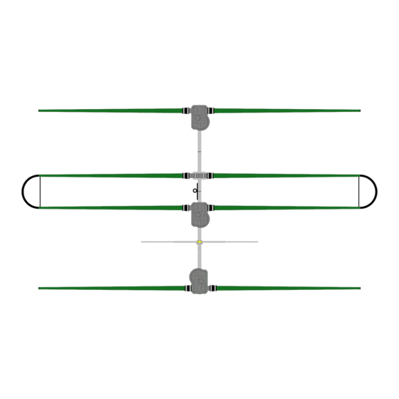
Page 22: Antenna Layout Drawing - 2 Element
SteppIR Antennas 40m - 30m Dipole Kit • Finally wrap each of the quick disconnect boots (rubber) between the clamps with two layers of the premium all weather electrical tape the same way as you wrap the joints on the FTP’s (Picture 15). Remember to stretch the tape tight and smooth it down while wrapping. -
Page 23: Element
SteppIR Antennas 40m - 30m Dipole Kit 3 E l e m e n t Y a g i S p a c i n g Drawing 17 a n d I n s t a l l a t i o n L a y o u t... -
Page 24: Element
SteppIR Antennas 40m - 30m Dipole Kit New Antenna Specifications With The 40m - 30m Dipole Installed → Specifications 2 Element Yagi 3 Element Yagi 4 Element Yagi W / 40m - 30m Weight → 37 lb / 16.8 kg 58 lb / 23.1 kg... -
Page 25: Appendix A - 6M Passive (Early 3 Element Reconfiguration)
SteppIR Antennas 40m - 30m Dipole Kit Appendix A: 6 Meter Passive Installation (3 Element) The use of the optional 6m passive element on 3 element antennas configured at the end of 2003 and later (Drawings 17) or earlier antennas modified to the new configuration do not present any problems working with the new 40m - 30m dipole kit. -
Page 26: Appendix B - Controller (Upgrade)
SteppIR Antennas 40m - 30m Dipole Kit Appendix B: Controller (Upgrade) Unless your firmware is version 6.704 or later you will need to update your controller firm- ware with the provided chip. If you do not know what version of firmware you have on your controller the version number will appear in the upper right hand corner of the controller dis- play (Picture A) when you first turn it on. -
Page 27: Appendix C - Cpu (Firmware Chip) Replacement Procedures
CPU (chip) Replacement Procedures Appendix C: Retract elements ● Press 'Mode' button until you see 'Setup Mode' (Setup light will also come on) ○ Press 'Select' button (within 4 seconds) ○ Press 'Up' or 'Dn' button to scroll to 'Retract Elements' ○... - Page 28 CPU (chip) Replacement Procedures Chip Extractor Chip Extractor Picture 2 Picture 3 Use a chip extractor (Picture 2 & 3) to carefully pull the chip out of its socket. The ● tiny “claws” on the extractor fit at the chip corners, and hook under the chip. Gently pull the chip upwards, rocking slightly as necessary until it is free.
- Page 29 CPU (chip) Replacement Procedures Picture 5 Firmware chip in its socket Center the chip in the socket and press the chip down vertically with your thumb ● (Picture 5). Press evenly until the chip is firmly seated on all sides. Reinstall the driver board to the display board (Picture 1) ●...
-
Page 30: Appendix D - Controller Firmware Version 6.7 Or Later
Version 6.7 or later In a effort to improve the operation of the Steppir antenna and to address the problems that can come up in the myriad of installations we have a new version of firmware for all of our Yagis. - Page 31 New SteppIR Controller Firmware General Freq Mode When the controller is in this mode there are several options: The Transceiver Interface sets the operating frequency. ● The Options menu is selectable in this mode. ● The Band buttons are programmable in this Mode.
- Page 32 New SteppIR Controller Firmware 3) 40/30 Dipole selection- Button #4 toggles between having the 40/30 Dipole option installed or not. The band LED needs to be lit when the Dipole option is present to use it. CAUTION do not enable this option if the Dipole is not installed, it may be possible to damage your driven element if you do.
-
Page 33: Appendix E - Troubleshooting Guide
Yagi Troubleshooting Guide Appendix E: The Most Common Problems (Read this First!) The antenna is out of calibration, perform the calibration as described in the manual. ● The factory defaults have been inadvertently changed, reset factory defaults “all”. There ● are two default modes, “all”... - Page 34 Yagi Troubleshooting Guide GENERAL: Be aware that just because the controller display says an element is a certain length there is no guarantee that it is, the motor could be running backwards due to a miss-wire, the element could have mechanical problems, or a broken wire in the control cable (the motor will run with only one winding driven in some cases) or a faulty driver board.
- Page 35 Yagi Troubleshooting Guide CABLE PROBLEMS: The control cable uses 4 wires per motor (one motor in each element housing). Each motor has two wires for each of its two motor windings. This test assumes the antenna is connected to one end of the control cable and the measurements are taken at the 25-pin connector that mates to the controller.
- Page 36 Yagi Troubleshooting Guide The 4 Element & MonstIR: (each have a driven, director 1, director 2 & reflec- tor) Pin Numbers Driven 1 – 2 20 ohms (approximately) 3 – 4 20 ohms Director 1 5 – 6 20 ohms 7 –...
- Page 37 Yagi Troubleshooting Guide Two or More Elements are Swapped: ● This is easy to do if you don’t mark the 4 conductor cables before you tape them along the boom. The SWR will usually be high on every band. Often by changing the controller frequency, while keeping the transmit frequency fixed, the SWR may go quite low at a higher or lower controller frequency.
- Page 38 Yagi Troubleshooting Guide Mechanical problems can range from an obstruction in the element, usually in the tip, such as packing material or in rare cases fiberglass bumps or imperfections. We check this by running a gauge in the tip but once in a great while that doesn’t catch it. DO NOT ever tape or block the end of the element tip, water can collect and freezing can cause a blockage or trap the element.
-
Page 39: Appendix F - Replacing The Driven Element Bracket
SteppIR Antennas - 3 Element Appendix F: Replacing the Driven Element Bracket (Original 3 element only) For customers who purchased a 3 element antenna before March 2003 your element housing brackets may have been of a different design (Figure 3-C). If you have the original style element housing bracket you will need to install a new style element housing bracket on your boom (Figure 3) before you can mount the new 40m - 30m driven element housing unit. - Page 40 SteppIR Antennas - 3 Element 4 8 . 0 0 4 8 . 0 0 4 . 2 5 4 8 . 0 0 2 . 2 5 4 8 . 0 0 3 0 . 0 0 5 0 . 2 5 9 4 .
-
Page 41: Steppir Warranty
(2) years from date of sale. Do not modify this product or change physical construction without the written permission of SteppIR Antennas Inc. This limited warranty is automatically void if the following occurs: improper installation, unauthorized modifications, physical abuse or damage from severe weather, beyond the manufacturer's control. - Page 42 40m - 30m Dipole Option www.steppir.com Yagi Dipole Vertical...
Need help?
Do you have a question about the 2 Element Yagi and is the answer not in the manual?
Questions and answers