SteppIR 2 Element Yagi Instruction Manual
Hide thumbs
Also See for 2 Element Yagi:
- Instruction manual (42 pages) ,
- Instruction manual (20 pages) ,
- Instruction manual (54 pages)
Table of Contents

Related Manuals for SteppIR 2 Element Yagi


Summary of Contents for SteppIR 2 Element Yagi
- Page 1 2 Element Yagi Instruction Manual 2 Element Yagi with 40/30 Loop (not to scale) 2 Element Yagi 20-6m (not to scale) Manual REV 3.52 February 22 2023 13406 SE 32nd St, BELLEVUE WA, 98005 WWW.CONSUMER.STEPPIR.COM TEL: (425)-453-1910...
- Page 2 Improper specification of an antenna or rotator to a tower can result in product failure, injury or death. SteppIR is not an expert on tower or rotator sizing and for this reason will never offer any recommendation – this specification process is meant for industry professionals such as a structural engineer, tower manufacturer or rotator manufac- turer.
-
Page 3: Table Of Contents
Stainless Steel Fastener Information Antenna Direction Configuration Antenna Overview and Diagram Section 1: 2 Element Yagi Boom Assembly Section 2: Connecting the Mast Plate and Return Tube to the Boom 17-21 Section 3: Control Cable, Connector Junction Box, and EHU Wiring... -
Page 4: Steppir - Why Compromise
SteppIR to be a commercially feasible product. The current and future SteppIR products should produce the most potent single tower antenna systems ever seen in Amateur Radio! We thank you for using our SteppIR antenna for your ham radio endeavors. -
Page 5: Preamble By Jim Streible
3. Do a complete inventory of every part, nut and bolt. Yes it takes time, but it also allows you to notify SteppIR if anything is missing and allow time to get it to you before you start assembly of the anten- na. - Page 6 SWR and resonant point. You don’t want to damage the an- tenna due to high power being applied with a large mismatch. 10. Enjoy the antenna! Jim Streible—K4DLI Jim passed away in early 2016, but his advice has enduring value. 13406 SE 32nd St, BELLEVUE WA, 98005 WWW.CONSUMER.STEPPIR.COM TEL: (425)-453-1910...
-
Page 7: Steppir Design
Al- so, since the SteppIR can control the element lengths, a long boom is not needed to achieve near optimum gain and front to back ratios on 20 - 10 meters. -
Page 8: Abbreviations
ABBREVIATIONS 13406 SE 32nd St, BELLEVUE WA, 98005 WWW.CONSUMER.STEPPIR.COM TEL: (425)-453-1910... -
Page 9: Parts Checklist
Kit, EHU Lid Hardware - 1 for Driven and 1 for Passive 72-0054-01 70-6002-01 2E 6m Passive element Kit, 2E/3E 6m hardware 72-0014-01 09607 High Wind Mast Kit; 2 or 3 element Yagi QR Code Sheet - Instruction Manuals 13406 SE 32nd St, BELLEVUE WA, 98005 WWW.CONSUMER.STEPPIR.COM TEL: (425)-453-1910... - Page 10 Kit, UrbanBeam/2E EHU Cable Assemblies and 16” Coax Seal DESCRIPTION ✓ PART # Control cable, 4 conductor EHU Cable Assembly, 13’ 2 ft 21-5001-01 16 in 09-1022 Coax seal, 1/2” width 13406 SE 32nd St, BELLEVUE WA, 98005 WWW.CONSUMER.STEPPIR.COM TEL: (425)-453-1910...
- Page 11 Kit, EHU Lid Hardware ✓ PART # DESCRIPTION 60-0019 Nut, 10-32, Nylock, S/S 60-0017-10 Screw, 10-32 x 7/8", Flathead, Phillips Screw, 10-32 7/8", Panhead, S/S 60-0061 Washer, 10-32, Flat, S/S (5c) 60-0018 13406 SE 32nd St, BELLEVUE WA, 98005 WWW.CONSUMER.STEPPIR.COM TEL: (425)-453-1910...
- Page 12 72-0014-01 Kit, 2E/3E 6m Hardware DESCRIPTION ✓ PART # 60-0003 U-BOLT & SADDLE, 1-3/4” Screw, 6-32 x 3/4", Panhead 60-0011 Nut, 6-32 Nylock 60-0014 60-0046 Nut, 5/16" -18, Nylock, S/S 13406 SE 32nd St, BELLEVUE WA, 98005 WWW.CONSUMER.STEPPIR.COM TEL: (425)-453-1910...
-
Page 13: Stainless Steel Fastener Information
Save yourself a lot of grief and always use a thread lubricant when working with stain- less steel fasteners. 13406 SE 32nd St, BELLEVUE WA, 98005 WWW.CONSUMER.STEPPIR.COM TEL: (425)-453-1910... -
Page 14: Antenna Direction Configuration
The driven element is a dipole when on 40 and 30 meters Passive Element 20m-6m Driven / 40m-30m Dipole 20m-6m Driven / 40m-30m Dipole Figure 1.01: 2 Element Yagi with 40/30 20m-6m Director 20m-6m Reflector Passive Element 20m-6m Driven 20m-6m Driven Figure 1.02: 2 Element Yagi 20-6m... -
Page 15: Antenna Overview And Diagram
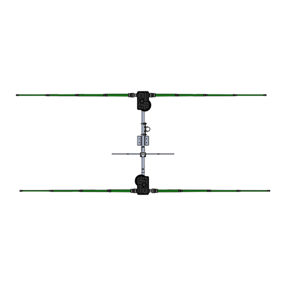
22 in. from center of driven element center of 6m to center of 6m passive element passive ele- ment 57 in. 57 in. Director Driven Director Driven *Not to scale Figure 1.04 13406 SE 32nd St, BELLEVUE WA, 98005 WWW.CONSUMER.STEPPIR.COM TEL: (425)-453-1910... -
Page 16: Section 1: 2 Element Yagi Boom Assembly
Section 1.1: Assemble the Boom The 2 element SteppIR Yagi boom consists of two sections of aluminum tubing that are 60 inch- es long x 1-3/4” OD x 1/8” wall, along with two aluminum antenna housing brackets as shown in Figure 1.11. -
Page 17: Section 2: Connecting The Mast Plate And Return Tube To The Boom
Hex Bolt, 5/16” x 4” 60-0046 Nylock Nut, 5/16 60-0017 Pan Screw, 10-32 x 3/4” 60-0112 Set Screw, 10-32 x 1/4”, Cup Point Figure 2.11 Use anti-seize on all stainless hardware! 13406 SE 32nd St, BELLEVUE WA, 98005 WWW.CONSUMER.STEPPIR.COM TEL: (425)-453-1910... - Page 18 Figure 2.22 Determining the Direction of the Antenna The SteppIR Yagi has three “directions” in which it can be used. Normal, 180 degree and Bi- directional. When the antenna is installed on its mast the passive element should be facing the direction the rotator indicates.
- Page 19 Although the EHUs are shown in the diagram, they should not be mounted to the boom yet—they are here for reference. Director Use anti-seize on all stainless hardware! Figure 2.32 Director Driven 13406 SE 32nd St, BELLEVUE WA, 98005 WWW.CONSUMER.STEPPIR.COM TEL: (425)-453-1910...
- Page 20 Figure 2.42 Director Use anti-seize on all stainless hardware! 1.75” SS U-bolts/ saddles for Boom Director Driven 2” SS U-bolts/ saddles for Boom Driven 13406 SE 32nd St, BELLEVUE WA, 98005 WWW.CONSUMER.STEPPIR.COM TEL: (425)-453-1910...
- Page 21 Figure 2.52. Key Qty Part # Description Figure 2.51 60-0003 U-Bolt & Saddle, 1-3/4" Nut, 5/16" -18, Nylock, 60-0046 Use anti-seize on all stainless hardware! Top view Figure 2.52 Driven Director 13406 SE 32nd St, BELLEVUE WA, 98005 WWW.CONSUMER.STEPPIR.COM TEL: (425)-453-1910...
-
Page 22: Section 3: Control Cable, Connector Junction Box, And Ehu Wiring
For first time setups it is common for this to be only partially installed, re- sulting in fault codes on the controller. 0.25” 2.75” Figure 3.11 Figure 3.21 Figure 3.22 Figure 3.23 13406 SE 32nd St, BELLEVUE WA, 98005 WWW.CONSUMER.STEPPIR.COM TEL: (425)-453-1910... - Page 23 WIRING THE CONTROL CABLE TO THE DB25 SPLICE SKIP TO NEXT PAGE IF YOU HAVE A PREWIRED CABLE FIGURE 3.24 Figure 3.25 13406 SE 32nd St, BELLEVUE WA, 98005 WWW.CONSUMER.STEPPIR.COM TEL: (425)-453-1910...
- Page 24 (different mast plates and connector junction box locations will vary the lengths)—it’s much easier to account for too long of a cable than too short! Figure 3.31 Since the 2 element Yagi does not have a reflector, the asso- ciated plug in the connector junction box is not used.
- Page 25 EHU OVERVIEW If you have a prewired EHU, you may skip to page 27. Figure 3.40 gives an overview of the inside of a SteppIR EHU. Wiring of each EHU will be cov- ered in detail on the following pages.
- Page 26 Figure 3.43 shows a red line crossing out the text in ques- tion. The orange circle shows the correct wiring sequence. 0.25 1.5” Figure 3.41 Figure 3.42 Figure 3.43 4 Pin Header Wiring Sequence BLACK GREEN WHITE Figure 3.44 13406 SE 32nd St, BELLEVUE WA, 98005 WWW.CONSUMER.STEPPIR.COM TEL: (425)-453-1910...
- Page 27 12. When finished, the EHU will be sealed with the gasket and lid, and secured to the EHU brackets on the boom. Figure 3.45 Figure 3.46 Figure 3.47 Figure 3.48 Figure 3.49 13406 SE 32nd St, BELLEVUE WA, 98005 WWW.CONSUMER.STEPPIR.COM TEL: (425)-453-1910...
-
Page 28: Section 4: Ehu Wiring Tests
Record your results in the “Results” column. (100’ is about 23 ohms). Resistance Test Table Pin Pair Antenna Element Expected Resistance Results (ohms) ~ 20 Ohms Driven ~ 20 Ohms ~ 20 Ohms Director ~ 20 Ohms 13406 SE 32nd St, BELLEVUE WA, 98005 WWW.CONSUMER.STEPPIR.COM TEL: (425)-453-1910... - Page 29 This is an open loop system and the controller has no way of knowing if the elements are really moving when commanded to. 13406 SE 32nd St, BELLEVUE WA, 98005 WWW.CONSUMER.STEPPIR.COM TEL: (425)-453-1910...
-
Page 30: Section 5: Attaching The Ehus To The Element Brackets
Note: The driven element and return tube will have the EST (offset tube) lined up so that the short side and long side of the EST/return tube are facing in the same directions. The director element EST configuration will be the opposite. This is normal. 13406 SE 32nd St, BELLEVUE WA, 98005 WWW.CONSUMER.STEPPIR.COM TEL: (425)-453-1910... - Page 31 ATTACHING THE EHUS TO THE ELEMENT BRACKETS Figure 5.12 Figure 5.11 Use anti-seize on all stainless hardware! 13406 SE 32nd St, BELLEVUE WA, 98005 WWW.CONSUMER.STEPPIR.COM TEL: (425)-453-1910...
-
Page 32: Section 6: Telescoping Poles, Sweeps, And Foam Plug Assemblies
SHOULD BE ABLE TO SEE LIGHT AT THE OTHER END IF THE POLE IS KEPT STRAIGHT. DEBRIS INSIDE THE TELESCOPING POLES CAN LEAD TO FAILURE OF THE EHU. 1.1” x 6” 1.5” x 6” 1.5” x 6” Figure 6.14 (PN 10-1059-01) (PN 10-1059-21) (PN 10-1059-01) 13406 SE 32nd St, BELLEVUE WA, 98005 WWW.CONSUMER.STEPPIR.COM TEL: (425)-453-1910... - Page 33 12. Remember, the heat shrink will want to slide as it’s heated. Reposition it as it cools to make sure the joint is fully covered. The heat shrink will be hot; wear insulated gloves. Figure 6.24 Figure 6.25 Old style sweep with shorter shoulder 13406 SE 32nd St, BELLEVUE WA, 98005 WWW.CONSUMER.STEPPIR.COM TEL: (425)-453-1910...
- Page 34 1.1” x 6” polyolefin heat shrink Sweep Clamp Notch Sweep Clamp Notch Figure 6.26 Figure 6.28 0.25” GAP Sweep Diverter Use anti-seize on Only turn the all stainless NUT when tight- hardware! ening! 13406 SE 32nd St, BELLEVUE WA, 98005 WWW.CONSUMER.STEPPIR.COM TEL: (425)-453-1910...
- Page 35 20. Repeat the previous steps on the other side of sweep tube. BOTTOM Use anti-seize on all stainless hardware! Only turn the NUT when tight- ening! Figure 6.31 Figure 6.32 13406 SE 32nd St, BELLEVUE WA, 98005 WWW.CONSUMER.STEPPIR.COM TEL: (425)-453-1910...
- Page 36 23. Figure 6.44 shows the completed sweep—repeat the process for each sweep. Fiberglass spreader rod Figure 6.42 Figure 6.41 Use anti-seize on Only turn the all stainless NUT when tight- hardware! ening! Figure 6.44 Figure 6.43 5/16” 13406 SE 32nd St, BELLEVUE WA, 98005 WWW.CONSUMER.STEPPIR.COM TEL: (425)-453-1910...
- Page 37 Insert the foam plug assembly onto the telescoping pole tip as shown in Figure 6.53. Be sure that the plastic housing bottoms out on the pole tip. Repeat for the other telescoping pole tip. Figure 6.51 Figure 6.53 Figure 6.52 13406 SE 32nd St, BELLEVUE WA, 98005 WWW.CONSUMER.STEPPIR.COM TEL: (425)-453-1910...
-
Page 38: Section 7: Cpvc Guide Tubes And Diverter Cones, Attaching Fiberglass Poles, And Trusses
SKIP TO THE NEXT PAGE IF YOU DO NOT HAVE THE 40/30 LOOP The 40/30 loop on the 2 Element Yagi uses a plastic tube and a diverter cone located inside the tele- scoping pole, to guide the copper strip out of the EHU. Note that the straight elements do not use this inner tube, only the 40/30 loops. - Page 39 Quick disconnect boot locking ring (these are molded into the base section of each telescoping pole and are used to keep the pole from sliding out of the quick disconnect boots in high wind situations) 13406 SE 32nd St, BELLEVUE WA, 98005 WWW.CONSUMER.STEPPIR.COM TEL: (425)-453-1910...
- Page 40 For the straight elements you only need to follow the steps concerning the telescoping pole and quick disconnect boot, there is no CPVC inner guide tube. Figure 7.22 Figure 7.23 Figure 7.24 Figure 7.25 Figure 7.26 Figure 7.27 Figure 7.28 13406 SE 32nd St, BELLEVUE WA, 98005 WWW.CONSUMER.STEPPIR.COM TEL: (425)-453-1910...
- Page 41 ELEMENT TRUSS OVERVIEW SKIP TO PAGE 46 IF YOU DO NOT HAVE THE 40/30 LOOP 13406 SE 32nd St, BELLEVUE WA, 98005 WWW.CONSUMER.STEPPIR.COM TEL: (425)-453-1910...
- Page 42 10-32 x 1/4” SS Set Screw 10-1054-02 30m / 40m truss support Figure 7.32—Side View Figure 7.31—Top View Use anti-seize on all stainless hardware! Figure 7.34 Figure 7.35 Figure 7.33 13406 SE 32nd St, BELLEVUE WA, 98005 WWW.CONSUMER.STEPPIR.COM TEL: (425)-453-1910...
- Page 43 Dacron rope is secured to the truss line. Figure 7.46 shows a tied truss line before electrical tape is applied. Use anti-seize on all stainless hardware! Figure 7.42 Figure 7.43 Figure 7.41 Figure 7.44 Figure 7.45 Figure 7.46 13406 SE 32nd St, BELLEVUE WA, 98005 WWW.CONSUMER.STEPPIR.COM TEL: (425)-453-1910...
- Page 44 “stacked” one on top of the other as shown in Figure 7.56. Tighten the wire clips firmly. Figure 7.51 Figure 7.52 Figure 7.54 Figure 7.53 Figure 7.55 Figure 7.56 13406 SE 32nd St, BELLEVUE WA, 98005 WWW.CONSUMER.STEPPIR.COM TEL: (425)-453-1910...
- Page 45 Figure 7.65 shows the loop being adjusted. Figure 7.66 shows the level and parallel half of the 40/30 element. Use anti-seize on all stainless hardware! Figure 7.62 Figure 7.61 Figure 7.63 Figure 7.64 Figure 7.65 Figure 7.66 13406 SE 32nd St, BELLEVUE WA, 98005 WWW.CONSUMER.STEPPIR.COM TEL: (425)-453-1910...
-
Page 46: Section 8: 6 Meter Passive Element (Included)
Part # Description 60-0003 U-Bolt & Saddle, 1-3/4" 60-0046 Nut, 5/16" -18, Nylock, S/S 60-0011 Screw, 6-32 x 3/4”, Panhead 60-0014 Nut, 6-32 Nylock Figure 8.03 Director Driven 13406 SE 32nd St, BELLEVUE WA, 98005 WWW.CONSUMER.STEPPIR.COM TEL: (425)-453-1910... -
Page 47: Ptt Lockout Tuning Relay (Included)
PTT LOCKOUT TUNING RELAY (INCLUDED) To prevent application of unintended, excessive RF power while the SteppIR antenna is tuning, the SDA 100 and OptimizIR controller provides an isolated pair of contacts from a 3.5 mm ste- reo jack to interrupt the PTT relay signal to a linear amplifier. The cable is provided, but any standard 3.5 mm stereo plug to two RCA plug cable sold for audio applications works well in... -
Page 48: Voltage/Surge Suppressor (Optional)
8. We recommend sealing up the connections by either using silicone tape or electrical tape to wrap the entire Voltage/Surge Suppressor and cable connections so that they do not corrode from moisture. Figure 9.02 Figure 9.03 13406 SE 32nd St, BELLEVUE WA, 98005 WWW.CONSUMER.STEPPIR.COM TEL: (425)-453-1910... -
Page 49: Grounding The Controller
Figure 9.04: Lug location for SDA100, OptimizIR, and OptimizIR 2.0 (early models) Figure 9.05: Lug location for OptimizIR 2.0 (stainless steel chassis) 13406 SE 32nd St, BELLEVUE WA, 98005 WWW.CONSUMER.STEPPIR.COM TEL: (425)-453-1910... -
Page 50: How To Tune Your Yagi (Mandatory)
SteppIR antenna tunes are broken up into “segments” which we use to create an ideal antenna at a specific frequency. Each segment consists of a frequency, element lengths, and some mis- cellaneous display settings like gain, F/R, and beam width. - Page 51 If tuning a 2E 20-6m (no 40/30m dipole) then segment 7 will be the last segment you tune. Please refer to the create/modify section of the controller manual and our Tech Support Video section on our website for more information on tuning. OptimizIR Manual: https://consumer.steppir.com/wp-content/uploads/2018/05/SDA-2000-OptimizIR-Manual-Version-1_4- April-17-2018.pdf Tech Support Videos: https://consumer.steppir.com/support/tech-support-videos/ 13406 SE 32nd St, BELLEVUE WA, 98005 WWW.CONSUMER.STEPPIR.COM...
- Page 52 If tuning a 2E 20-6m (no 40/30m dipole) then segment 7 will be the last segment you tune. Please refer to the create/modify section of the controller manual and our Tech Support Video section on our website for more information on tuning. SDA100 Manuals: Mustang Firmware: https://consumer.steppir.com/wp-content/uploads/2020/10/SDA100-Operators-Guide-MUSTANG.pdf Pinto Firmware: https://consumer.steppir.com/wp-content/uploads/2011/10/operations-manual-SDA-100-rev-2-dec-12.pdf Tech Support Videos: https://consumer.steppir.com/support/tech-support-videos/ 13406 SE 32nd St, BELLEVUE WA, 98005 WWW.CONSUMER.STEPPIR.COM...
-
Page 53: Steppir Options
STEPPIR OPTIONS 40m - 30m Dipole Retrofit • “Y” Cable • Transceiver Interface (Rig Specific) • Voltage suppressor (12 conductor) Element Expansion Kit Dipole 2 Element • 2 Element 3 Element 13406 SE 32nd St, BELLEVUE WA, 98005 WWW.CONSUMER.STEPPIR.COM TEL: (425)-453-1910... -
Page 54: Product Warranty Claim
Shipping instructions will be issued to the buyer for defective compo- nents, and shipping charges to the factory will be paid for by the buyer. SteppIR will pay for stand- ard shipping back to the buyer. The manufacturer assumes no further liability beyond repair or re- placement of the product. - Page 55 13406 SE 32nd St, BELLEVUE WA, 98005 WWW.CONSUMER.STEPPIR.COM TEL: (425)-453-1910...
Need help?
Do you have a question about the 2 Element Yagi and is the answer not in the manual?
Questions and answers