Table of Contents
Advertisement
Quick Links
ASSEMBLY MANUAL
This assembly manual is intended to be
COLOR
printed in full
. If the manual is
printed in
black and
white, many im-
portant details could be lost.
REV 1.24
8/12/2022
Page 1
13406 SE 32nd Street, Bellevue, WA 98005 l Tel: 425.453.1910 l email: sales@steppir.com
Support: steppir.com/support ⚫ Tel: 425.453.1910 ⚫ support@steppir.com
Advertisement
Table of Contents

Related Manuals for SteppIR YAGI URBAN BEAM


Summary of Contents for SteppIR YAGI URBAN BEAM
- Page 1 . If the manual is printed in black and white, many im- portant details could be lost. REV 1.24 8/12/2022 Page 1 13406 SE 32nd Street, Bellevue, WA 98005 l Tel: 425.453.1910 l email: sales@steppir.com Support: steppir.com/support ⚫ Tel: 425.453.1910 ⚫ support@steppir.com...
-
Page 2: Antenna Specifications
9.63 (F/S) 6.50 16.5 12.0 12.6 24.6 14.0 18.5 15.7 6.65 14.8 14.8 6.15 A full size dipole is referenced at 2.1dBi Measured SWR is 2.3:1 for this model on 30m Page 2 Support: steppir.com/support ⚫ Tel: 425.453.1910 ⚫ support@steppir.com... -
Page 3: Table Of Contents
Mast Plate-to-Boom Overview Drawing Attaching Boom to Mast Plate Wiring the Connector Junction Box Mounting the Connector Junction Box Section 3 — Boom Wiring & Initial Testing 29-31 Wiring the 25pin Dsub Wiring Test Page 3 Support: steppir.com/support ⚫ Tel: 425.453.1910 ⚫ support@steppir.com... - Page 4 Securing the element tubes to the EHU 39-40 Mounting the UrbanBeam to the Tower Mast Last Steps Section 6 — Troubleshooting 43-44 Troubleshooting tips 43-44 Section 7 — Miscellaneous 45-46 Warranty Contact Information Page 4 Support: steppir.com/support ⚫ Tel: 425.453.1910 ⚫ support@steppir.com...
-
Page 5: Youtube Assembly Instructions By Pascal Villenueve, Va2Pv
If typing these links in are laborious, simply go to www.youtube.com and then type in Pascal Villeneuve, Urban Beam, and the three links will appear. Special thanks to Pascal Villeneuve VA2PV for the time he spent making these in- credible 4K HD Videos! Page 5 Support: steppir.com/support ⚫ Tel: 425.453.1910 ⚫ support@steppir.com... -
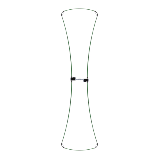
Page 6: Urban Beam Drawing
Page 6 Support: steppir.com/support ⚫ Tel: 425.453.1910 ⚫ support@steppir.com... -
Page 7: Preamble
3. Do a complete inventory of every part, nut and bolt. Yes it takes time, but it also allows you to notify SteppIR if anything is missing and allow time to get it to you before you start assembly of the antenna. - Page 8 When done enabling, troller off, and back on again 9. Enjoy the antenna! Jim Streible—K4DLI Jim passed away in early 2016, but his advice has enduring value. Page 8 Support: steppir.com/support ⚫ Tel: 425.453.1910 ⚫ support@steppir.com...
-
Page 9: Parts Checklist
8” x 8” x 0.25” Aluminum mast plate (for use with aluminum saddles) 70-2025-23 CPVC Liner 40” without coupler 70-2025-13 CPVC Liner 49” with coupler Instruction summary sheet with manual QR codes Page 9 Support: steppir.com/support ⚫ Tel: 425.453.1910 ⚫ support@steppir.com... - Page 10 Urban Beam Yagi has been selected and saved before you use the controller. Failure to do so can cause damage to your antenna. Page 10 Support: steppir.com/support ⚫ Tel: 425.453.1910 ⚫ support@steppir.com...
-
Page 11: Assembly Kits-Bill Of Materials
60-0065 5/16” x 3.5” Hex head bolt, SS 60-0114 5/16” x 3.75” Hex head bolt, SS 60-0046 5/16” -18 SS Nylock nut 60-0112 10-32 x 1/4” SS Set Screw cup point Page 11 Support: steppir.com/support ⚫ Tel: 425.453.1910 ⚫ support@steppir.com... - Page 12 #10 washer, SS 60-0019 10-32 Nylock nut, SS UrbanBeam Glue, Tape & Anti-Seize Kit 72-0041-21 PART NUMBER DESCRIPTION ✓ 72-0009-03 Glue kit 09-0001 66’ PVC electrical tape 10-1028-01 Anti-Seize Stick 10-1509-02 Diverter cone Page 12 Support: steppir.com/support ⚫ Tel: 425.453.1910 ⚫ support@steppir.com...
-
Page 13: Assembly Notes (Read Before You Start Assembly)
When the power is “off” on your controller, there is still a very small amount of power feeding to the stepper motors, to effectively “lock” them in place. This reduces the need for calibration of the antenna. Page 13 Support: steppir.com/support ⚫ Tel: 425.453.1910 ⚫ support@steppir.com... -
Page 14: A Word About Stainless Steel And The Potential For Galling
Save yourself a lot of grief and always use a thread lubricant when working with stainless steel fasteners. Page 14 Support: steppir.com/support ⚫ Tel: 425.453.1910 ⚫ support@steppir.com... -
Page 15: Antenna Overview
Prepare the Boom with EHUs, Mast Plate, and Connector Box • Prepare the Element Tubes & Loop Tubes • Final Assembly & Testing • FORWARD DIRECTION (Normal) REVERSE DIRECTION (180 deg) 20m-6m Director 40m, 20m-6m Driven Page 15 Support: steppir.com/support ⚫ Tel: 425.453.1910 ⚫ support@steppir.com... -
Page 16: Section 1 - Boom / Mast Plate Assembly
It’s important to pay attention to the orientation of the EHUs on the boom, making sure that the ESTs (where the loop elements attach) are positioned to be closest to the ends of the boom. Page 16 Support: steppir.com/support ⚫ Tel: 425.453.1910 ⚫ support@steppir.com... -
Page 17: Ehu Mounting Locations
PREPARING THE BOOM ASSEMBLY EHU Mounting Locations EHU CENTER-TO-CENTER SPACING MEASUREMENTS It is critically important that the center-to-center spacing is correct when assembling your SteppIR Ya- gi. Use Figure 1.00 for placement of each of the elements. Start from the left edge of the boom and measure from there. -
Page 18: Ehu Placement
All the drawings in this manual are oriented so that you are looking inward at boom with the director to the left and the driven to the right, as shown in Figure 1.01. 70-3420-01 70-3403-01 Director EHU Driven EHU FIG. 1.01 Page 18 Support: steppir.com/support ⚫ Tel: 425.453.1910 ⚫ support@steppir.com... -
Page 19: Ehu Overview
Even if the power is turned off of the controller, damage can occur. This is the number one cause of antenna installation failures, so please be sure to heed the advice. Figure 1.02 gives an overview of the inside of a SteppIR EHU. FIG. 1.02 Element support... -
Page 20: Ehu Wiring
The 4-conductor cable has black shielding, with only 4 conduc- tors. FIG. 1.11 FIG. 1.10 FIG. 1.13 FIG. 1.12 4 Pin Header Wiring Sequence BLACK GREEN WHITE TERMINAL PLUG TERMINAL HEADER FIG. 1.14 Page 20 Support: steppir.com/support ⚫ Tel: 425.453.1910 ⚫ support@steppir.com... - Page 21 Repeat wiring and coax seal preparation for all EHUs. When finished, the EHUs will be secured to the aluminum element mounting plates. This is covered in detail in the next chapter. Page 21 Support: steppir.com/support ⚫ Tel: 425.453.1910 ⚫ support@steppir.com...
-
Page 22: Director Ehu Drawing
60-0046 5/16” Nylock nut 70-3420-01 Director EHU 10-1502-01 Element housing gasket 10-1015-11 Element mounting plate 10-1601-03 1-3/4” Aluminum saddle half 60-0112 10-32 x 1/4” SS Set Screw cup point C (x10) Page 22 Support: steppir.com/support ⚫ Tel: 425.453.1910 ⚫ support@steppir.com... -
Page 23: Attaching Director Mounting Plate & Ehu To Boom
Level the EHU as shown in Figure 1.37, tighten the aluminum saddles firmly, and then tighten the set screws (PN 60-0112). FIG. 1.31 FIG. 1.32 FIG. 1.34 FIG. 1.33 FIG. 1.35 FIG. 1.36 FIG. 1.37 Page 23 Support: steppir.com/support ⚫ Tel: 425.453.1910 ⚫ support@steppir.com... -
Page 24: Driven Ehu Drawing
60-0046 5/16” Nylock nut 70-3420-01 Director EHU 10-1502-01 Element housing gasket 10-1015-11 Element mounting plate 10-1601-03 1-3/4” Aluminum saddle half 60-0112 10-32 x 1/4” SS Set Screw cup point C (x10) Page 24 Support: steppir.com/support ⚫ Tel: 425.453.1910 ⚫ support@steppir.com... -
Page 25: Attaching Driven Mounting Plate & Ehu To Boom
Level the EHU as shown in Figure 1.37, tighten the aluminum saddles firmly, and then tighten the set screws (PN 60-0112). Figure 1.50 shows the boom with two EHUs FIG 1.50 Page 25 Support: steppir.com/support ⚫ Tel: 425.453.1910 ⚫ support@steppir.com... -
Page 26: Mast Plate-To-Boom Overview Drawing
1.75” x .75” Aluminum Saddle Half 60-0065 5/16” x 3.5” Hex head bolt, SS 60-0065 5/16” -18 SS Nylock nut 60-0112 10-32 x 1/4” SS Set Screw cup point 70-2034 Connector junction box, 2E and 3E Page 26 Support: steppir.com/support ⚫ Tel: 425.453.1910 ⚫ support@steppir.com... -
Page 27: Attaching Boom To Mast Plate
10-32 x 5/16” SS buttonhead (makes attach- ing antenna to the mast much easier) FIG. 2.10 FIG. 2.12 FIG. 2.11 FIG. 2.13 FIG. 2.15 FIG. 2.14 Assembly of the Boom/Mastplate is now complete. Page 27 Support: steppir.com/support ⚫ Tel: 425.453.1910 ⚫ support@steppir.com... -
Page 28: Wiring The Connector Junction Box
Scanning the QR code below will take you directly to the manuals page. Manuals Page 28 Support: steppir.com/support ⚫ Tel: 425.453.1910 ⚫ support@steppir.com... -
Page 29: Mounting The Connector Junction Box
For more information on mounting the connector junction box, refer to the complete manual found on our site at steppir.com/manuals, or scan the QR code on the previous page (page 28) to go there di- rectly. -
Page 30: Wiring The 25Pin Dsub
The DB25 Field Splice replaces the standard connector with a convenient solder-less connection of the control cable to the SteppIR controller. Follow the steps below to connect it to your control cable. 1. Apply dielectric grease to the exposed copper portion of each wire. -
Page 31: Wiring Test
Verify that each element works correctly and then unplug the controller’s power supply be- • fore disconnecting the control cable. FIG. 3.20 Page 31 Support: steppir.com/support ⚫ Tel: 425.453.1910 ⚫ support@steppir.com... -
Page 32: Section 4 - Preparing Telescoping Poles And Loop Tubes
The heat shrink will want to slide as it is heated so wear gloves and reposition the heat shrink to keep it cen- tered on the joint as needed. Caution: The heat shrink will be HOT, wear insulated gloves! Page 32 Support: steppir.com/support ⚫ Tel: 425.453.1910 ⚫ support@steppir.com... - Page 33 Once this step is complete, the fiberglass pole should be connected to the sweep material with the di- verter in between, and the heat shrink should be holding it all together, as shown in Figure 4.10. FIG. 4.09 FIG. 4.08 SWEEP DIVERTER GLUE HEAT SHRINK SWEEP FIG. 4.10 Page 33 Support: steppir.com/support ⚫ Tel: 425.453.1910 ⚫ support@steppir.com...
-
Page 34: Sizing The Pole Tip Remnants For Loop Tubes
FIG. 4.11 grip tape “cut 2” “cut 1” Sweep Diverter chamfer chamfer fiberglass pole fiberglass pole Tube piece left over from Telescoping Tube Preparation 1.0” Section 4.0 41.5” thickest end thinner end Page 34 Support: steppir.com/support ⚫ Tel: 425.453.1910 ⚫ support@steppir.com... -
Page 35: Attaching Sweep Couplers To Sweep Tubes
Figure 4.15. FIG. 4.13 FIG. 4.12 Mark on sweep coupler Sweep tubing Fiberglass Telescoping Pole Sweep Diverter FIG. 4.14 FIG. 4.15 Page 35 Support: steppir.com/support ⚫ Tel: 425.453.1910 ⚫ support@steppir.com... -
Page 36: Connecting The Metal Loop Strut To The Sweep Couplers
• Figure 4.27 shows the completed sweep—repeat the process for each sweep. FIG. 4.22 FIG. 4.23 FIG. 4.21 FIG. 4.24 FIG. 4.25 FIG. 4.27 FIG. 4.26 5/16” Page 36 Support: steppir.com/support ⚫ Tel: 425.453.1910 ⚫ support@steppir.com... -
Page 37: Joining The Loop Halves Together
Loop Half. FIG. 4.31 FIG. 4.32 FIG. 4.33 .25” drain hole (must face the ground for water drainage) pole tip 3/4” (.75” FIG. 4.36 FIG. 4.35 FIG. 4.34 3/4” (.75”) 3/4” (.75”) Page 37 Support: steppir.com/support ⚫ Tel: 425.453.1910 ⚫ support@steppir.com... -
Page 38: Preparing The Cpvc Inner-Guide Tube & Diverter Cone
39-7/8” pipe GLUE GLUE FIG. 4.44 FIG. 4.43 FIG. 4.42 3/4” FIG. 4.46 FIG. 4.47 FIG. 4.45 Page 38 Support: steppir.com/support ⚫ Tel: 425.453.1910 ⚫ support@steppir.com... -
Page 39: Section 5 - Final Assembly
Description 10-1006-22 Quick disconnect boot 10-1013-02 Telescoping pole Inner guide tube assembly consisting of diverter cone , 39- 7/8” and 49” CPVC Plastic tube, glued together. (NOT USED FOR THE DIRECTOR) Page 39 Support: steppir.com/support ⚫ Tel: 425.453.1910 ⚫ support@steppir.com... - Page 40 FIG. 4.61 FIG. 4.62 FIG. 4.63 FIG. 4.64 FIG. 4.65 Page 40 Support: steppir.com/support ⚫ Tel: 425.453.1910 ⚫ support@steppir.com...
-
Page 41: Mounting The Urbanbeam To The Tower Mast
SteppIR offers saddle sizes in 1-3/4”, 2”, 2-1/4”, 2- 1/2” and 3”. Since all SteppIR antenna’s come with the standard 2 inch saddles, that is the verbiage used in the instructions that follow. -
Page 42: Last Steps
If you do not see an SWR dip STOP HERE and find the problem. 11. Get the UrbanBeam Yagi on that tower so you can work some good DX! Page 42 Support: steppir.com/support ⚫ Tel: 425.453.1910 ⚫ support@steppir.com... -
Page 43: Section 6 - Troubleshooting
TROUBLESHOOTING THE URBANBEAM YAGI TROUBLESHOOTING TIPS SteppIR antennas are all powered by stepper motors, hence the name. Stepper motors function by rotating the shaft a specific number of “steps” per revolution. The SDA 100 or OptimizIR directs the stepper motors to extend the elements a particular number of steps to the required length. - Page 44 3.0) when measuring the voltages, a suggestion would be to use a bare 25 pin D-Sub to plug into the SteppIR controller and then insert a paper clip to penetrate the pin hole. Usually about .75″ long will do the trick. One paper clip being longer than the other also helps.
-
Page 45: Section 7 - Miscellaneous
SteppIR will pay for standard shipping back to the buyer. The manufacturer assumes no further liability beyond repair or re- placement of the product. -
Page 46: Contact Information
Technical support videos can be found at steppir.com/videos, or by scanning the QR code to go there directly: If the support site does not have a fix, please contact us at support@steppir.com Information and questions about our products: sales@steppir.com Phone / Fax: Phone: 425-453-1910 —... - Page 47 13406 SE 32nd Street, Bellevue, WA 98005 l Tel: 425.453.1910 l email: sales@steppir.com...
Need help?
Do you have a question about the YAGI URBAN BEAM and is the answer not in the manual?
Questions and answers