
Related Manuals for SteppIR BigIR


Summary of Contents for SteppIR BigIR
- Page 1 BigIR Antenna Assembly Manual REV 5.1 09/30/2021 13406 SE 32nd St. Bellevue, WA 98005 | consumer.steppir.com | 425.453.1910 | sales@steppir.com...
-
Page 2: Table Of Contents
Section 4: Prepare the CPVC liner Section 5: Prepare the EST Extension assembly Section 6: Mounting the BigIR Counterpoise/Radial system overview - Ground mounted or elevated? How to tune your vertical (mandatory) Product warranty claim Tech Support: consumer.steppir.com/support | 425.453.1910 | support@steppir.com... -
Page 3: Steppir-Why Compromise
STEPPIR—WHY COMPROMISE? The SteppIR antenna was originally conceived to solve the problem of covering the six ham bands (20m, 17m, 15m, 12m, 10m and 6m) on one tower without the performance sacrifices caused by interaction be- tween all of the required antennas. -
Page 4: Preparing For Assembly
Even with power off, damage can occur. When the power is “off” on your controller, there is still a very small amount of power feeding to the stepper motors, to effectively “lock” them in place. This leads to less need for calibration of the antenna. Tech Support: consumer.steppir.com/support | 425.453.1910 | support@steppir.com... -
Page 5: Antenna Specifications
Adjustable elements Power rating 3.0 KW (1000W limit on 60/80m bands) Feed points Frequency coverage 3.4-55 MHz with loading coil, 7.0- 54MHz without Control cable 2 x 4 conductor with coil, 1x without Tech Support: consumer.steppir.com/support | 425.453.1910 | support@steppir.com... -
Page 6: Antenna Overview
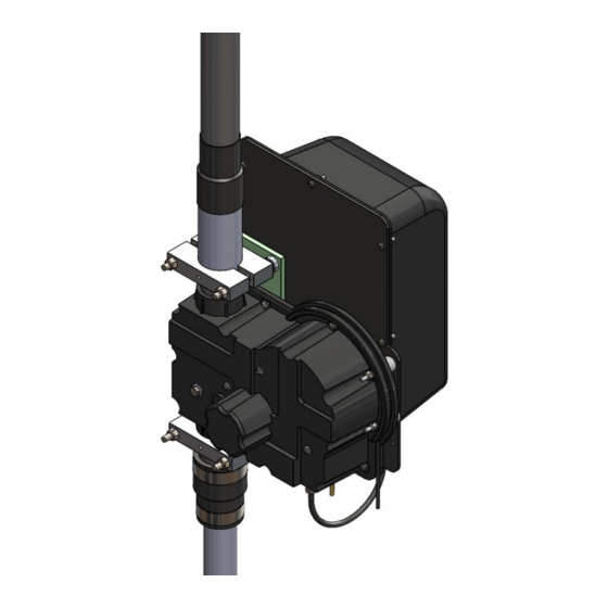
ANTENNA OVERVIEW The BigIR is a vertical antenna that can be adjusted for resonance on the 40, 30, 20, 17, 15, 12, 10 and 6 meter ham bands, including frequencies in between. With the addition of the 80 meter coil accessory, the BigIR/80 will also provide coverage on 80 and 60 meters, including frequencies in between. -
Page 7: Parts Checklist
10-1013-02 Telescoping Pole, 18 foot 4 section BigIR EST extension with aluminum coupler - Lower 70-2019-01 BigIR EST extension with aluminum coupler and ring - Upper 70-2020-01 CPVC Liner for BigIR, 89"x3/4", with coupler 70-2021-01 CPVC Liner for BigIR, 89" x 3/4", w/o coupler... - Page 8 72-0044-04 Kit, BigIR Mark IV Hardware/Heat Shrink DESCRIPTION ✓ PART # QUICK DISCONNECT, 1-1/2" to 1-1/4", Fernco 60-1006-22 Hose Clamp, 1.16" to 2" ID, Used for BigIR, S/S 60-6000-20 10-1104-11 O-Ring, 1-3/4" x 2", EP DM 72-0009-03 Kit, Glue 10-1029-01 Connector Protector Cat, 0.14 oz, (silicon goop for terminals)
- Page 9 60-0027 Bolt, 1/4"-20 x 1", S/S 60-0030 Nut, 1/4"-20, Nylock, S/S Quick Link, 3/16", S/S 60-0094 06021 80M Base loading Coil for the BigIR ✓ PART # DESCRIPTION 70-2101-01 Coil, 80m, BigIR 72-0044-20 Kit, BigIR Mark IV 80m Coil Hardware...
-
Page 10: Ehu Overview
EHU OVERVIEW Figure 1 provides an overview of a SteppIR EHU (the specific model shown is a 20m driven). Element Support Tube (EST) EHU terminal header Sprocket/Stepper motor Platen Balun (yagi driven EHU only) Spool with copper tape SO-239 (driven EHU only) -
Page 11: Section 1: Wiring And Ehu/Coil Assembly
Figure 1.12 shows a blue line crossing out the text in question. The orange circle shows the correct wiring sequence. 0.25 1.5” Figure 1.10 Figure 1.11 Figure 1.12 4 Pin Header Wiring Sequence BLACK GREEN WHITE Figure 1.13 Tech Support: consumer.steppir.com/support | 425.453.1910 | support@steppir.com... - Page 12 EHU. Repeat this process to the remaining areas of the wire tray as shown in figure 1.19. 12. When finished, the EHU will be secured to the high wind reinforcing kit and optional loading coil. Figure 1.15 Figure 1.16 Figure 1.17 Figure 1.18 Figure 1.19 Tech Support: consumer.steppir.com/support | 425.453.1910 | support@steppir.com...
- Page 13 Do not install if using 80m coil Use anti-seize on all SS hardware! Part Number Description EHU, BigIR (with control cable & coax seal) 10-1501-22 Cover for EHU, no drain hole 10-1502-12 EHU Gasket 60-0017 Pan Screw, 10-32 x 3/4”...
- Page 14 Washer, 5/16", Flat, S/S 10-1613-11 AL Spacer, 1/4" X 5/16" ID X 3/4" OD 60-0046 Nut, 5/16" -18, Nylock, S/S 60-0071 Screw, 10-32 x 1", Panhead, Phillips, S/S 60-0018 Washer, 10-32, Flat 60-0019 Nut, 10-32, Nylock Tech Support: consumer.steppir.com/support | 425.453.1910 | support@steppir.com...
- Page 15 Part Number Description 60-0095 Screw, 10-32 x 2", Panhead, Phillips, S/S 60-1004-01 Spacer, 1/2", Nylon 10-1613-11 AL Spacer, 1/4" X 5/16" ID X 3/4" OD 60-0018 Washer, 10-32, Flat 60-0019 Nut, 10-32, Nylock Tech Support: consumer.steppir.com/support | 425.453.1910 | support@steppir.com...
- Page 16 Section 1.3 (continued): 80M Base Coil Installation (skip if 80m coil is not pur- chased) EHU ground lug Use a dielectric grease on the center conductor and threads, and coax seal for the exterior of the connection. Tech Support: consumer.steppir.com/support | 425.453.1910 | support@steppir.com...
- Page 17 5. A small piece of coax seal should be used to seal the outer insulation of the 4 conductor control cable as well (figure 1.45). Figure 1.41 Figure 1.42 Figure 1.43 Figure 1.44 Figure 1.45 Figure 1.46 Tech Support: consumer.steppir.com/support | 425.453.1910 | support@steppir.com...
- Page 18 Once the antenna is mounted and your radial set- up is prepared, the radials can then be attached to the ground lug on the coil, and coax seal can be applied to all external electrical connections on the EHU/coil. Tech Support: consumer.steppir.com/support | 425.453.1910 | support@steppir.com...
- Page 19 7. Plug the DB25 splice into the back of the controller, ensuring that it is fully seated, and twist the thumb- screws to secure it. We have seen customers install these partially, resulting in fault codes on the control- ler. 0.25” 2.75” Figure 1.20 Figure 1.30 Figure 1.31 Tech Support: consumer.steppir.com/support | 425.453.1910 | support@steppir.com...
- Page 20 *Ensure that the shield wire for both the EHU and loading coil connect to the “G” terminal on the DB25 connector, and trim them at the EHU/ coil so they are not connected to anything. Shield Coil Tech Support: consumer.steppir.com/support | 425.453.1910 | support@steppir.com...
-
Page 21: Section 2: Ehu/Coil Wiring Test
9. If the tape extends properly, press the retract button to retract the elements and proceed to the next as- sembly step. Figure 2 3.75” 2.95” OptimizIR (extended) SDA100 (inset) Tech Support: consumer.steppir.com/support | 425.453.1910 | support@steppir.com... -
Page 22: Section 3: Prepare The Telescoping Pole
Each line needs to change color to en- sure even adhesion temperatures. • We recommend wearing heat-resistant gloves while doing this so that you can reposition the heat-shrink as needed (it will try to slide down the pole). Figure. 3.1 Tech Support: consumer.steppir.com/support | 425.453.1910 | support@steppir.com... - Page 23 • Insert the plastic housing onto the telescoping pole tip as shown in figure 3.2. Be sure that the telescop- ing pole bottoms out on the vent tube. Figure. 3.2 Tech Support: consumer.steppir.com/support | 425.453.1910 | support@steppir.com...
-
Page 24: Section 4: Prepare The Cpvc Liner
Work quickly as the glue will dry quickly and become less effective • Be sure to save some glue for later, as this will be used to install the CPVC liner onto the BigIR EHU during final as- sembly. -
Page 25: Section 5: Prepare The Est Extension Assembly
Polyolefin Heat Shrink 2.05” x 4” 10-1104-11 O-ring, 1-3/4” x 2” 60-6000-20 Hose Clamp, 1.16” to 2“ ID, SS 60-1006-22 Quick Disconnect, 1-1/2” to 1-1/4” 10-1105-11 Vertical Pole Rain Cap 72-0046-01 BigIR Guy Kit Tech Support: consumer.steppir.com/support | 425.453.1910 | support@steppir.com... - Page 26 From the pole box, identify the upper and lower EST extensions (PN 70-2019-01 & 70-2020-01 respec- tively) and set on a clean and dry surface. • From the BigIR Mark IV Hardware/Heat Shrink kit (PN 72-0044-04) remove the following components: Part Number Description 10-1104-11 O-Ring, 1-3/4"...
- Page 27 EST extension assembly. Note: press the hose clamp firmly to be butted against the O-ring/coupler. Figure 5.6 • The completed assembly should look like figure 5.7 below: Figure 5.7 Tech Support: consumer.steppir.com/support | 425.453.1910 | support@steppir.com...
- Page 28 At this point the CPVC liner assembly can be slid into the EST extension assembly, and the telescoping fiberglass pole assembly can be affixed to the top of the upper EST extension assembly with the use of the provided quick disconnect boot (PN 60-1006-22). See page 25 for additional reference. Tech Support: consumer.steppir.com/support | 425.453.1910 | support@steppir.com...
-
Page 29: Section 6: Mounting The Bigir
OD - 1/8” wall. One end of the tube has been swaged to an outer diameter of 1.48” such that it will fit into the EHU assembly. Note that most 1.5” OD tubes/pipes will not fit in the SteppIR EHU due to the tight fiberglass tolerances, so it is recommended to use ours. - Page 30 EHU, and the EST assembly will have to be clamped to the high wind kit. 1) Use the provided glue kit (PN 72-0039) to bond the CPVC liner to the BigIR EHUs CPVC stub.
- Page 31 EHU ground lug Note: If using radial distribution plate, be sure to use a thick braided or solid ground strap between the EHU/Coil ground lug and radial plate (coil ground lug shown on page 18). Tech Support: consumer.steppir.com/support | 425.453.1910 | support@steppir.com...
-
Page 32: Counterpoise/Radial System Overview - Ground Mounted Or Elevated
This counterpoise usually consists of a system of radial wires placed either on the ground or ele- vated above ground. This is not an in depth publication but simply a general guide on installing and using SteppIR verticals. There is much more information available in various publications if you need it. The ARRL Antenna Handbook is a good source for additional information. - Page 33 4. Skimping on radials just isn’t worth it, EVERTHING is improved with more radials, 25 – 30 is about where diminishing returns begin, the minimum recommended is 16. Graph 1 Number of Radials Number of radials Tech Support: consumer.steppir.com/support | 425.453.1910 | support@steppir.com...
- Page 34 4 Radials -1.2 0.06 0.12 0.18 0.24 0.36 0.42 0.48 0.54 Radil Length in Wave length Radial length in wavelength 0.48 0.32 Graph 3 0.24 0.16 0.08 Number of Radials (N) Number of radials Tech Support: consumer.steppir.com/support | 425.453.1910 | support@steppir.com...
- Page 35 To raise this low impedance closer to the desired 50 ohms you can angle the radials downward, this raises the impedance of the antenna as you increase the angle downward. Graph 4 (next page) shows the approximate relationship of radial angle to impedance: Tech Support: consumer.steppir.com/support | 425.453.1910 | support@steppir.com...
- Page 36 (3 ft x 3 ft is just enough to “connect” to salt water), you want to be certain that the metal does not cor- rode over time. For long term immersion, Monel is a good (but fairly expensive ) choice. Aluminum has been successfully used if you clean it periodically. Tech Support: consumer.steppir.com/support | 425.453.1910 | support@steppir.com...
-
Page 37: How To Tune Your Vertical (Mandatory)
SteppIR antenna tunes are broken up into “segments” which we use to create an ideal antenna at a specific frequency. Each segment consists of a frequency, element lengths, coil switch command, and some miscellaneous display settings like gain, F/R, and beam width. - Page 38 9900 10100 6900 7150 5200 5350 3750 3875 3600 3675 3500 3550 3400 3450 Please refer to the create/modify section of the controller manual for more information on tuning SDA 100 Manual: https://consumer.steppir.com/wp-content/uploads/2020/10/SDA100-Operators-Guide-MUSTANG.pdf Tech Support: consumer.steppir.com/support | 425.453.1910 | support@steppir.com...
- Page 39 5200 5250 4100 4150 4000 4050 3750 3875 3600 3675 3500 3550 3400 3450 Please refer to the create/modify section of the controller manual for more information on tuning OptimizIR Manual: https://consumer.steppir.com/wp-content/uploads/2018/05/SDA-2000-OptimizIR-Manual-Version-1_4-April-17 -2018.pdf Tech Support: consumer.steppir.com/support | 425.453.1910 | support@steppir.com...
-
Page 40: Product Warranty Claim
Shipping instructions will be issued to the buyer for defective components, and shipping charges to the factory will be paid for by the buyer. SteppIR will pay for standard shipping back to the buyer. The manufacturer assumes no further liability beyond repair or replacement of the product. - Page 41 Tech Support: consumer.steppir.com/support | 425.453.1910 | support@steppir.com...
Need help?
Do you have a question about the BigIR and is the answer not in the manual?
Questions and answers