SteppIR 2 Element Yagi Instruction Manual
Hide thumbs
Also See for 2 Element Yagi:
- Instruction manual (42 pages) ,
- Instruction manual (20 pages) ,
- Instruction manual (55 pages)

Related Manuals for SteppIR 2 Element Yagi


Summary of Contents for SteppIR 2 Element Yagi
- Page 1 2 Element Yagi Instruction Manual 2 Element Yagi with 40/30 Loop 2 Element Yagi Manual REV 3.5 January 4 2023 13406 SE 32nd St, BELLEVUE WA, 98005 WWW.STEPPIR.COM TEL: (425)-453-1910...
- Page 2 Improper specification of an antenna or rotator to a tower can result in product failure, injury or death. SteppIR is not an expert on tower or rotator sizing and for this reason will never offer any recommendation – this specification process is meant for industry professionals such as a structural engineer, tower manufacturer or rotator manufac- turer.
-
Page 3: Table Of Contents
TABLE OF CONTENTS SteppIR - Why Compromise? Preamble by Jim Streible SteppIR Design Abbreviations Parts Checklist 9-11 Stainless Steel Fastener Information Antenna Direction Configuration Antenna Overview and Diagram 15-16 Section 1: Connecting the Boom to the Mast Plate 17-21 Section 2: Control Cable, Junction Box, and EHU Wiring... -
Page 4: Steppir-Why Compromise
SteppIR to be a commercially feasible product. The current and future SteppIR products should produce the most potent single tower antenna systems ever seen in Amateur Radio! We thank you for using our SteppIR antenna for your ham radio endeavors. -
Page 5: Preamble By Jim Streible
3. Do a complete inventory of every part, nut and bolt. Yes it takes time, but it also allows you to notify SteppIR if anything is missing and allow time to get it to you before you start assembly of the antenna. - Page 6 PREAMBLE OK - - - NOW WHAT? (continued) (Sage advice from Jim Streible, K4DLI—SteppIR Technical Support Guru) Your Antenna Has Arrived! What is the first thing to do? (continued) 5. When you have finished working with the controller be sure the display indicates “Elements Home”...
-
Page 7: Steppir Design
Al- so, since the SteppIR can control the element lengths, a long boom is not needed to achieve near optimum gain and front to back ratios on 20 - 10 meters. -
Page 8: Abbreviations
ABBREVIATIONS... -
Page 9: Parts Checklist
PARTS CHECKLIST It is important that you do an inventory of the items that were shipped to you. Nothing is worse than discovering a day before a planned installation that there are missing parts! We do our very best to ensure that you receive everything needed for construction of your antenna, but better to be safe than sorry—inventory your parts well in advance of your installation. - Page 10 PARTS CHECKLIST What Comes in the Sweep Box DESCRIPTION ü PART # 09607 High Wind Mast Kit; 2 or 3 element Yagi Poly Sweeps (100psi) 10-1153-01 10-1511-01 Sweep diverter Polyolefin Heat Shrink 1.1” x 6” 10-1059-21 10-1503-21 Fiberglass rod, 3/8” x 31-3/4” long, black Kit, 30/40m Return Hardware 72-0008-11 72-0014-01...
- Page 11 PARTS CHECKLIST 09607 High Wind Mast Kit DESCRIPTION ü PART # 10-1021-43 Boom to Mast plate, 8", HIGH WIND with saddle holding holes Saddle, 2" x 3/4" 10-1601-22 Saddle, 1-3/4" x 3/4" 10-1601-03 Bolt, 5/16" x 3-1/2", S/S (1c) 60-0065 60-0066 Bolt, 5/16"...
- Page 12 PARTS CHECKLIST 72-0018-31 Kit, 39' Element Truss, 2E, 3E, DB18/18E/36/42 end Elements DESCRIPTION ü PART # 10-1510-21 Element Truss Coupler (sets) Dacron double braided poly rope, 1/8" 75ft 21-7001-01 Saddle, 1-3/4" x 3/4" 10-1601-03 Turnbuckle, 1/4" x 4", Eye to Eye, S/S 60-0083 60-0110 Bolt, 1/4"-20 x 1-1/4", S/S...
-
Page 13: Stainless Steel Fastener Information
STAINLESS STEEL FASTENER INFORMATION From time to time, we get complaints from customers regarding galling of stainless steel fasteners. Here is an excerpt from the Industrial Fastener Institute's Standards Book: Thread galling seems to be the most prevalent with fasteners made of stainless steel, aluminum, titanium and other alloys which self-generate an oxide surface film for corrosion protection. -
Page 14: Antenna Direction Configuration
ANTENNA DIRECTION CONFIGURATION REVERSE DIRECTION FORWARD DIRECTION (Normal) (180 deg) 20m-6m Director 20m-6m Reflector Passive Element 20m-6m Driven 20m-6m Driven 20m-6m Director 20m-6m Reflector The driven element is a dipole when on 40 and 30 meters Passive Element 20m-6m Driven / 40m-30m Dipole 20m-6m Driven / 40m-30m Dipole... -
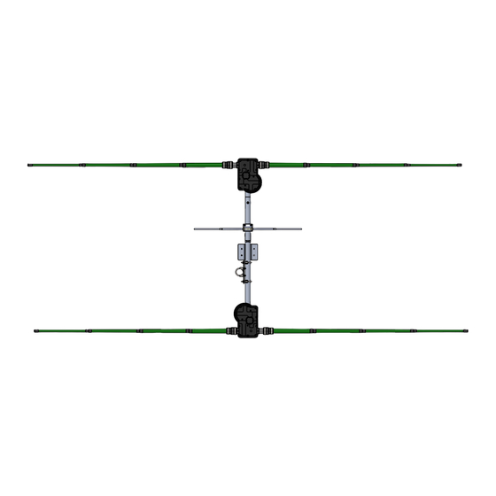
Page 15: Antenna Overview And Diagram
ANTENNA OVERVIEW AND DIAGRAM 2E Without 40m-30m Dipole Kit 2E With 40m-30m Dipole Kit (not to scale) (not to scale) Figure 1.00 Boom / Mast Plate Boom / Mast Plate 6m Passive 114 in. long 6m Passive 114 in. long Mast Mast Splice... - Page 16 2 ELEMENT YAGI INSTALLATION AND BOOM ASSEMBLY The 2 element SteppIR Yagi boom consists of two sections of aluminum tubing that are 60 inch- es long x 1-3/4” OD x 1/8” wall, along with two aluminum antenna housing brackets as shown in Figure 1.
-
Page 17: Section 1: Connecting The Boom To The Mast Plate
CONNECTING THE BOOM TO THE MAST PLATE Section 1.1: Install the Mast Clamp (High Wind Kit) Older antennas attach the mast plate differently. Skip to page 23 if you do NOT have the high wind kit. The mast plate is connected to the boom using hardware from the high wind kit (part number 09607). - Page 18 Nylock Nut, 3/8” Determining the Direction of the Antenna The SteppIR Yagi has three “directions” in which it can be used. Normal, 180 degree and bi- directional. When the antenna is installed on its mast the passive element should be facing the direction the rotator indicates.
- Page 19 CONNECTING THE BOOM TO THE MAST PLATE Section 1.3: Install the High Wind Kit · Position the high wind kit using the drawing below as reference. · Mark a hole on the top of the boom directly under the eyebolt stud, 24.40” from the bracket of the Di- rector EHU.
- Page 20 CONNECTING THE BOOM TO THE MAST PLATE Section 1.4: Install the Mast Clamp (No High Wind Kit) The mast plate has 8 pre-drilled holes. Four are used for the 2” stainless steel mast clamps, and four more are used for the 1-3/4” stainless steel boom clamps. Connect the boom to the mounting plate (figure 1.41), using the 1-3/4”...
- Page 21 INSTALL RETURN TUBE Section 1.5: Attach Return Tube to the Boom Skip if you do not have the 40/30 loop The return tube is installed next to the mast plate, as shown below. Make sure the U-bolts/ saddles are positioned over the reinforced rings on the return tube, and be careful not to over- tighten the nuts on the ends of the U-bolts.
-
Page 22: Section 2: Control Cable, Junction Box, And Ehu Wiring
WIRING/EHU/COIL ASSEMBLY Section 2.1: Preparing the control cable (skip if you have pre-wired cable) 1. Strip the jacket and aluminum shielding off of the control cable as shown in figure 2.10, approximate- ly 2.75” from end of control cable, being careful not to damage the individual wires. 2. - Page 23 WIRING THE CONTROL CABLE TO THE DB25 SPLICE SKIP IF YOU HAVE A PREWIRED CABLE FIGURE 2.22 Figure 2.23...
- Page 24 CONNECTOR JUNCTION BOX WIRING LAYOUT This drawing is here for your convenience—refer to the actual accessory Connector Junction Box instructions for more detail. If you have the pre-wired EHU cables, both EHUs will have around 13ft of cable and can just be plugged into the junction box.
- Page 25 EHU OVERVIEW If you have a prewired EHU, you may skip this section. Figure 2.24 gives an overview of the inside of a SteppIR EHU. Wiring of each EHU will be cov- ered in detail on the following pages. NEVER ATTEMPT ANY WIRING WHILE THE ELECTRONIC CONTROLLER IS CONNECTED TO THE CONTROL CABLE.
- Page 26 WIRING/EHU/COIL ASSEMBLY Section 2.3: Wiring the EHU (skip if you have pre-wired cable) 1. Trim approximately 1.5 inches of the outer jacket of the control cable. 2. Remove the outer foil shield, the support thread, and cut the shield wire off. 3.
- Page 27 WIRING/EHU/COIL ASSEMBLY 8. Check to be sure the terminal plug is firmly inserted into the terminal header. 9. Cut three 1-inch strips of coax seal for each EHU as shown in figure 2.34, and place them at each end of the wire tray of the EHU, as well as one in the center (figure 2.35). This trough acts as a strain relief so that the cable will not be pulled out of the EHU.
-
Page 28: Section 3: Ehu/Coil Wiring Tests
EHU/COIL WIRING TESTS Section 3.1: Resistance Test (mandatory) Figure 3.10 Figure 3.11 The control cable uses 4 wires per motor (one motor in each element housing unit (EHU)). Each motor has two wires for each of its two motor windings. This test assumes the antenna is connected to one end of the control cable and the measurements are taken at the 25-pin connector that mates to the controller (disconnected from controller). - Page 29 EHU/COIL WIRING TESTS Section 3.2: Open Circuit Test (mandatory) Step 4: Next make sure there is an open circuit between the following pins. Record your results in the “Results” column. (Any reading < 100 K ohms is bad) Open Circuit Test Table Results (Ohms or Open Load Expected Resistance (OL))
-
Page 30: Section 4: Mounting Ehus To The Boom
ATTACH THE ELEMENT HOUSING TO THE ELEMENT BRACKET Section 4.1: Mounting EHUs to the Boom Place the flat side of the element housing unit (EHU) on top of the element to boom brackets. The housing without the SO-239 coax connector is the director, the one with the SO-239 connector is the driven element (the balun is on the inside of this housing). - Page 31 ATTACHING THE ELEMENT HOUSING TO THE ELEMENT BRACKET 4.11 4.10 Use anti-seize on all stainless hardware!
-
Page 32: Section 5: Preparing Fiberglass Poles
PREPARING THE TELESCOPING POLE Section 5.1: Preparing the fiberglass pole 1. Extend the telescoping poles (PN 10-1013-02) to full length by firmly locking each section of the pole in place. A good methodology is to position each half of the joint so that they are several inches apart (while still within each other), and then pull quickly and firmly. - Page 33 PREPARING THE TELESCOPING POLE Section 5.2: Attaching sweeps and diverters to fiberglass 8. Use the glue kit (PN 72-0009-03) from the glue/tape kit to attach the sweep diverters (PN 10-1511-01) to the tips of the fiberglass telescoping poles. ONLY APPLY GLUE TO THE FIBERGLASS. Slowly rotate the sweep diverter as you slide it onto the pole to let the glue cover the most surface area possible.
- Page 34 ASSEMBLING SWEEPS · Refer to figure 5.20 during the following steps for an overview of the assembly process. · Each of the sweep coupler halves (PN 10-1155-01) will have a notch in the mold on one side marked with silver sharpie. IT IS CRITICAL THAT THESE NOTCHES ARE POINTING TOWARDS THE SWEEPS OR THEY WILL NOT WORK PROPERLY.
- Page 35 ASSEMBLING SWEEPS Section 5.3: Mounting the fiberglass spreaders 17. Mount the black fiberglass sweep spreaders (PN 10-1503-21) to the sweep couplers. There is a concave mounting area on each side of the plastic couplers. Position the fiberglass spreader so that the holes align with the clam shell couplers as shown in figure 5.23. When installing the fiberglass spreader, you will want the spreader to be underneath the plastic cou- pler as shown in figure 5.24.
- Page 36 ASSEMBLING SWEEPS Section 5.4: Final tightening 21. Finish tightening the four screws on the outside corners of the plastic coupler. Tighten evenly, in an automobile X type pattern as shown in figure 5.40. If you do not tighten evenly, you may break the fastener. Once the outsides are firmly tight, tighten the two screws that hold the fiberglass spreader in place.
-
Page 37: Section 6: Foam Plug Assemblies
ATTACHING FOAM PLUG HOUSING TO TELESCOPING POLE Section 6.1: Adding Foam Plug Assembly to the Telescoping Poles Each 20m-6m telescoping pole tip requires a breathable foam plug to allow for venting of the EHU. The foam plug assembly (PN 70-1007-01) consists of a special UV resistant foam plug material, and a plastic housing. -
Page 38: Section 7: Cpvc Guide Tubes And Diverter Cones, Attaching Fiberglass Poles
SKIP IF YOU DO NOT HAVE THE 40/30 LOOP The 40/30 loop on the 2 Element Yagi uses a plastic tube and a diverter cone located inside the tele- scoping pole, to guide the copper strip out of the EHU. Note that the straight elements do not use this inner tube, only the 40/30 loops. - Page 39 ATTACHING ELEMENTS TO THE EHUS Section 7.2: Securing the Element Support Tube (EST) to the EHUs When the CPVC inner guide tubes are completed, they will need to be inserted into the tele- scoping poles and secured to each EHU. Figure 7.20 below gives an overview of this proce- dure, with detailed instructions following on the next page.
- Page 40 ATTACHING ELEMENTS TO THE EHUS When attaching the telescoping fiberglass poles to each of the EHU’s, special care must be taken to en- sure that the rubber plugs that are in the base section of each pole are removed before placing the tele- scoping poles onto the EHU.
- Page 41 40/30 ELEMENT TRUSS KIT Section 7.3: Installing the Truss Support Mast SKIP IF YOU DO NOT HAVE THE 40/30 LOOP The great advantage of telescoping fiberglass poles are that they are both flexible and extremely strong. This is a significant advantage for such adverse weather situations as high winds, icing or snow accumu- lation.
- Page 42 40/30 ELEMENT TRUSS KIT Section 7.4: Attach the Truss Couplers SKIP IF YOU DO NOT HAVE THE 40/30 LOOP There are two pieces to the truss couplers (PN 10-1510-01) as shown in figure 7.40. The couplers are mounted on each side of the loop, located at the outer joint of the telescoping poles as shown in figure 7.41.
- Page 43 40/30 ELEMENT TRUSS KIT Section 7.5: Routing the Dacron Truss Cord SKIP IF YOU DO NOT HAVE THE 40/30 LOOP Before inserting the cord through the eyebolt of the 4” turnbuckle, unthread each eye so that there is approximately 3/8” thread remaining in the frame of the turnbuckle portion, as shown in figure 7.50. Locate the 1/8”...
- Page 44 40/30 ELEMENT TRUSS KIT Section 7.6: Leveling the elements When leveling the elements, use two adjustable wrenches as shown in figure 7.60. Be sure to ap- ply anti-seize to the threads of the eyebolts in the turnbuckle! The wrench that is placed on the thimble is held stationary, while the wrench that is on the frame of the turnbuckle is rotated.
-
Page 45: Meter Passive Element (Included)
6 METER PASSIVE ELEMENT (INCLUDED) The 6 meter passive element comes in 3 pieces. The main body with a 1/2” x 58” element section attached to it, and two 3/8” element sections (Figure 8.00). The overall length of the element is approximately 114” for the 2 element when assembled. The required fasteners will already be attached to each end of the 1/2”... -
Page 46: Ptt Lockout Tuning Relay (Included)
PTT LOCKOUT TUNING RELAY (INCLUDED) To prevent application of unintended, excessive RF power while the SteppIR antenna is tuning, the SDA 100 and OptimizIR controller provides an isolated pair of contacts from a 3.5 mm ste- reo jack to interrupt the PTT relay signal to a linear amplifier. The cable is provided, but any standard 3.5 mm stereo plug to two RCA plug cable sold for audio applications works well in... -
Page 47: Voltage/Surge Suppressor (Optional)
VOLTAGE/SURGE SUPPRESSOR (OPTIONAL) · The Voltage/Surge Suppressor is can be installed at the base of the tower, or on a well grounded structure (ground post or ground bus bar). · You will need to cut the control cable in order to install the Voltage/Surge Suppressor. MAKE SURE THAT THE POWER IS TURNED OFF AND UNPLUGGED ON THE CONTROLLER AS WELL AS THE CONTROL CABLE UNPLUGGED. -
Page 48: Grounding The Controller
GROUNDING THE CONTROLLER Make sure the controller is grounded. The ground lug locations are different for different controllers—the locations of the lugs for each type of controller are shown in the photos below. To ground, remove the yellow cap on the lug and take off the nut. Using a ring lug con- nect the grounding wire around the lug and secure it in place by screwing the nut back on, tight- en with a wrench. -
Page 49: How To Tune Your Yagi (Mandatory)
SteppIR antenna tunes are broken up into “segments” which we use to create an ideal antenna at a specific frequency. Each segment consists of a frequency, element lengths, and some miscellaneous display settings like gain, F/R, and beam width. - Page 50 7.85 8.85 8.35 6.95 7.85 7.15 40m (7.0-7.3) Please refer to the create/modify section of the controller manual and our Tech Support Video section on our website for more information on tuning. OptimizIR Manual: https://consumer.steppir.com/wp-content/uploads/2018/05/SDA-2000-OptimizIR-Manual-Version-1_4- April-17-2018.pdf Tech Support Videos: https://consumer.steppir.com/support/tech-support-videos/...
- Page 51 7.85 7.15 40m (7.0-7.3) Please refer to the create/modify section of the controller manual and our Tech Support Video section on our website for more information on tuning. SDA100 Manuals: Mustang Firmware: https://consumer.steppir.com/wp-content/uploads/2020/10/SDA100-Operators-Guide-MUSTANG.pdf Pinto Firmware: https://consumer.steppir.com/wp-content/uploads/2011/10/operations-manual-SDA-100-rev-2-dec-12.pdf Tech Support Videos: https://consumer.steppir.com/support/tech-support-videos/...
-
Page 52: Steppir Options
STEPPIR OPTIONS 40m - 30m Dipole (loop) · “Y” Cable · Transceiver Interface (Rig Specific) · Voltage suppressor (12 conductor) Element Expansion Kit Dipole 2 Element · 2 Element 3 Element... -
Page 53: Product Warranty Claim
Shipping instructions will be issued to the buyer for defective compo- nents, and shipping charges to the factory will be paid for by the buyer. SteppIR will pay for stand- ard shipping back to the buyer. The manufacturer assumes no further liability beyond repair or re- placement of the product. - Page 54 13406 SE 32nd St, BELLEVUE WA, 98005 WWW.STEPPIR.COM TEL: (425)-453-1910...
Need help?
Do you have a question about the 2 Element Yagi and is the answer not in the manual?
Questions and answers