Table of Contents
Advertisement
Quick Links
Advertisement
Table of Contents

Related Manuals for Lumel RP3


Summary of Contents for Lumel RP3
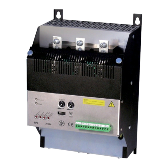
- Page 1 Three-phase power conTroller user’s manual...
-
Page 3: Table Of Contents
THREE-PHASE POWER CONTROLLER RP3 Type USER’S MANUAL CONTENTS 1. APPLICATION ....................5 2. BASIC REQUIREMEMNTS, OPERATIONAL SAFETY .......5 3. POWER CONTROLLER SET ...............6 4. INSTALLATION .....................6 4.1. Overall and assembly dimensions ............6 4.2. Electrical connections ................11 4.3. Selection of the control type ..............11 4.4. -
Page 5: Application
1. APPLICATION The RP3 power controller is a contactless three-phase power energy electronic device which includes a thyristor connector and an electronic gate triggering system. This power controller allows the control of the power delivered from a three- phase voltage source to an electrical energy load in function of the control signal input. -
Page 6: Power Controller Set
Remarks concerning the operator safety: 1. General - The RP3 power controller is destined to co-operate with other devices. - Non-authorized removal of the required housing, inappropriate use, incorrect installation or operation creates the risk of injury to personnel or damage to equipment. - Page 7 EMC legisla- tion. 5. Operation - Installations including RP3 power controllers must be equipped with protection devices according to the corresponding standard and regulations for prevention of accidents. - After the power controller has been disconnected from the supply voltage, live components and power connections must not be touched immediately because capacitors can be charged.
-
Page 8: Overall And Assembly Dimensions
4. INSTALLATION 4.1. Overall and assembly dimensions The RP3 power controller is destined to be mounted on a wall by means of holders. Power controller overall dimensions, spacing of assembly holes and the fixing way are presented on fig.1 and 2. - Page 9 4x M6 Terminals PE zaciski PE 2 holes M6x15 2otw. M6x15 Fuses Bezpieczniki B1, B2, B3 Osłona Panel Osłona Listwa zaciskowa Fig 4.1.b. The position of the power controller fuses for 40 A, Widok bez osłon 70 A and 125 A versions. (view after removing the cover) 4x M8 Cover Osłona...
- Page 10 Terminals PE 4x M8 zaciski PE Osłona 2 holes M10 2otw. M10 Fuses Bezpieczniki B1, B2, B3 Panel Listwa zaciskowa Fig. 4.2.b. he position of the power controller fuses for 200 A, 300A and 450 A Widok bez osłon Osłona versions (view after removing the cover) Fig.
-
Page 11: Electrical Connections
- wires of 16 mm cross-section, RP3-2x version; 70 A - wires of 25 mm cross-section, RP3-3x version; 125 A - wires of 50 mm cross-section, RP3-4x version; 200 A - rail of 100 mm cross-section, RP3-5x version; 300 A... - Page 12 Table 1. DIP switch section 0...5 V 0...10 V Input control signal 0...20 mA 4...20 mA Phase Kind of control Pulse - quick cycle Pulse - slow cycle On-Off (switching instantly) Load configuration Three-, six-wire* / four-wire 0 - open switch, 1 - shorted switch, - state resulting from other settings.
- Page 13 The control from a voltage or current control signal source or from the potentiometer Fig.4.6. Connection of control signals. is possible. In case of control from the potentiometer, the voltage input should be set on the 0...5 V range. b) by impulse signal One must connect the control signal (4...32 V) to terminals of the voltage input In-U, set on the 0...5 V range.
- Page 14 4.4.4. Analog outputs a) Output U = f (Io) 0...5 V/5 mA output voltage, proportional to the current value in the load circuit. Note: The measurement has a reference character. Fig.4.8. Analog outputs. 4.4.5. Relay outputs Semiconductor relays of MOSFET type. a) Output PK1.
-
Page 15: Connection Of Supply And Load
The supply of the strong-current circuit must be connected to U1, V1, W1 terminals, however the load circuit to U2, V2, W2 terminals (fig.1. and fig.2.) Fuses in version RP3 -1x , 2x and 3x are accessible after removing the protection cover, fig.4.1. -
Page 16: Power Control Service
4.5.2. Load connection in a 6-wire system. a) 6-wire load. 5. POWER CONTROLLER SERVICE „S-Start” and „Limit” potentiometers must be set on minimum, and the „Span” potentiometers, on maximum. In such settings, corresponding functions to them are inactive. One must carry out successively following operations: a) install the power controller, according to p.4.1. -
Page 17: Description Of Control Types
6. DESCRIPTION OF CONTROL TYPES 6.1. Control of ON-OFF type At the on-off control, the delivered power to the load is described by the following dependence: Where: Po - delivered power to the load, Xin - value of the input control signal. The power controller works in the semi-conductor relay mode. -
Page 18: Impulse Control
Fig. 6.2. Impulse control with a variable impulse frequency, runs of occurring signals . The RP3 power controller has following kinds of pulse control: Quick cycle, in which for X = 1/2 (X 25, 1 Hz,... -
Page 19: Phase Control
Runs of characteristic quantities for the impulse control are presented on the fig.6.3. The filling factor y is described by the following dependence: Fig.6.3. Runs of characteristic quantities for the impulse control with variable pulse frequency. 6.3. Phase control At phase control, a continuous change of delivered power to the load occurs, it is realised by the change of the load current turning on angle in the function of the analog control signal. -
Page 20: Limitation Of The Load Current
6.4. Limitation of the load current If the current value in the load circuit exceeds the boundary value set by means of the „Limit” potentiometer, then the current limitation operates regardless of the control signal value. It is possible to assign it from an external potentiome- ter, p. -
Page 21: Signalling Of Maximal Radiator Temperature Exceeding
6.9. Signalling of maximal radiator temperature exceeding The exceed of the 85C radiator temperature causes the automatic triggering stoppage and the display of signalling on the „Over Temp” diode, and the PK2 relay turning on, p.4.4.6b. The restart of the power controller is possible after the radiator cooling below 60C and the supply turning on to UWB again, p.4.5.1. -
Page 22: Specifications
7. SPECIFICATIONS Electrical parameters of the strong-current circuit. Table 2 Fuse parameters Max. Supply voltage Max. Lost output of the load load power in i Designation / manufacturer current circuit power thyristors at 415 V 50 A 50FE - Bussmann 3~400 V/50 Hz 30 kW <... - Page 23 EN 60947-4-2, EN 60947-4-3 - emission noise EN 60947-4-2, EN 60947-4-3 The RP3 power controller fulfils requirements of the EN 60947-4-3 standard. The power controller overload capacity is defined by parameters of the applied WARNING This product is an equipment of class A.
-
Page 24: Ordering Codes
..........7 other requirements ................X ORDERING EXAMPLE The code: RP3 - 3 - 8 means: RP3 - power controller of RP1 type, - maximal output current: 125 A, for the range of voltage: 3 - 400 V supplying the load circuit,... -
Page 25: Maintenance And Warranty
9. MAINTENANCE AND WARRANTY The RP3 power controller does not require any special periodical maintenance. In case of some incorrect operations: After the dispatch date and within the period stated in the warranty card One should return the power controller to the Manufacturer’s Quality Inspection Dept. - Page 28 LUMEL S.A. ul. Sulechowska 1, 65-022 Zielona Góra, POLAND tel.: +48 68 45 75 100, fax +48 68 45 75 508 www.lumel.com.pl Export department: tel.: (+48 68) 45 75 139, 45 75 233, 45 75 321, 45 75 386 fax.: (+48 68) 32 54 091...
Need help?
Do you have a question about the RP3 and is the answer not in the manual?
Questions and answers