Advertisement
Quick Links
Advertisement

Related Manuals for Lumel RP7


Summary of Contents for Lumel RP7
- Page 1 power controller user’s manual...
-
Page 3: Table Of Contents
POWER CONTROLLER RP7 TYPE USER’S MANUAL CONTENTS 1. APPLICATION ........................5 2. BASIC REQUIREMEMNTS, OPERATIONAL SAFETY ............5 3. POWER CONTROLLER SET ....................7 4. DESCRIPTION OF THE DESIGN and OPERATION ............7 5. INSTALLATION and SETTING TO WORK ................9 6. SPECIFICATIONS .......................10 7. ORDERING CODES ......................12... -
Page 5: Application
1. APPLICATION The RP7 power controller is destined to control the load power in function of the input control signal for following types of loads: resistance loads, resistance-inductance loads, and the control of induction motors and commutator motors at not high loads. - Page 6 Remarks concerning the operator safety: 1. General The RP7 power controller is destined to co-operate with other devices. Non-authorized removal of the required housing, inappropriate use, incorrect installation or operation creates the risk of injury to personnel or damage to equipment. For more detailed information please study the user’s manual.
-
Page 7: Power Controller Set
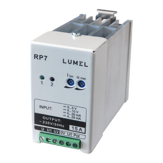
4. DESCRIPTION OF THE DESIGN AND OPERATION The RP7 power controller is destined to be mounted on a wall or on a rail (E-06292, DIN EN 50 022-35) by means of a special catch. - Page 8 - lighting green diode (1), signalling the exceeding over 70% of the set power, - lighting red diode (2), signalling the fuse damage. The RP7 power controller has a bidirectional thyristor switch, which is a link controlled by the gate triggering system. It also includes a fuse destined to protect semiconductor elements, an RC two-terminal network and a varistor, protecting against commutation or connection overvoltages.
-
Page 9: Installation And Setting To Work
Triggering delay of „Soft-start” type The „soft-start” type enables the change of the connection angle from to 0 rad in the time ca 1.5 s, after the supply connection (switch W, fig. 3). Detection and signalling of the load circuit current The 70% exceeding of the set current limitation value is signalled by the lighting of the green diode - 1 ... -
Page 10: Specifications
Table 1 Switch sections 0...5 V Control signal 0...10 V 0...20 mA 4...20 mA Kind of load Resistance Resistance-in- ductance 0 - switch in OFF position 1 - switch in ON position In case of assignment from the potentiometer, set the control signal on the range 0...10. The power controller setting to work includes: - The setting of the load current limitation (set the handwheel of the „... - Page 11 Supply voltage of the load circuit 195...230...253 V a.c Supply voltage frequency 47...50...53 Hz Power consumption of the gate 3.3 VA triggering system Minimal current output 100 mA Value of the output current in 15 mA (230 V) the locking state Power generated on the triac: Table 2...
-
Page 12: Ordering Codes
7. ORDERING CODES Code Description RP7 300 Power controller RP7 maximum output current 5A; documentation in English; test certificate... -
Page 13: Maintenance And Guarantee
8. MAINTENANCE AND GUARANTEE The RP7 power controller does not require any special periodical maintenance. In case of a fuse damage, the red diode (2) lights. To replace the fuse, one must: - disconnect the load circuit supply, - disconnect electrical connections from the terminal strip, - remove the power controller protection cover, - replace the fuse. - Page 14 LUMEL S.A. ul. słubicka 4, 65-127 Zielona Góra, poland tel.: +48 68 45 75 100, fax +48 68 45 75 508 www.lumel.com.pl Technical support: tel.: (+48 68) 45 75 143, 45 75 141, 45 75 144, 45 75 140 e-mail: export@lumel.com.pl Export department: tel.: (+48 68) 45 75 130, 45 75 132...
Need help?
Do you have a question about the RP7 and is the answer not in the manual?
Questions and answers