Table of Contents
Advertisement
Quick Links
Advertisement
Table of Contents

Subscribe to Our Youtube Channel
Related Manuals for THORLABS MLJ150


Summary of Contents for THORLABS MLJ150
- Page 1 MLJ150 Motorized Lab Jack Kinesis User Guide Original Instructions...
-
Page 2: Table Of Contents
Motorized Labjack Contents Chaper 1 Overview ....................1 1.1 Introduction ..................1 Chaper 2 Safety ......................5 2.1 Safety Information ................5 2.2 General Warnings ................5 Chaper 3 Mechanical Installation ................6 3.1 Unpacking ................... 6 3.2 Environmental Conditions ..............6 3.3 Mounting to a Work Surface ............. - Page 3 Appendices Appendix A Preventive Maintenance ............32 Appendix B Specifications ................33 Appendix C Stepper Motor Operation ............35 Appendix D Regulatory ................40 Appendix E Thorlabs Worldwide Contacts ..........42 Page 0 Rev B Apr 2018...
-
Page 4: Chaper 1 Overview
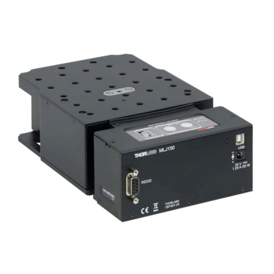
20 (M6) tapped holes and clearance slots for general mounting requirements. Fig. 1.1 MLJ150 Motorized Lab Jack The MLJ150 stages share many of the benefits of the Thorlabs range of motor controllers. These include USB connectivity (allowing multiple units to be used together on a single PC), fully featured Graphical User Interface (GUI) panels, and extensive software function libraries for custom application development. - Page 5 With the Kinesis system, .Net Controls are deployed to allow direct control over (and also reflect the status of) the range of electronic controller units, including the MLJ150 stages. Software applications that use .Net Controls are often referred to as 'client applications'.
- Page 6 Motorized Labjack Consider the control supplied for the MLJ150 integrated Labjack & controller. This Control provides a complete user graphical instrument panel to allow the stage to be manually operated, as well as a complete set of software functions (often called methods) to allow all parameters to be set and motor operations to be automated by a client application.
- Page 7 F1 key when running the Kinesis server, or via the Start menu, Start\Programs\Thorlabs\Kinesis\Kinesis Help. 1.1.2 Software Upgrades Thorlabs operate a policy of continuous product development and may issue software upgrades as necessary. The latest software can be downloaded from the ‘services’ section of www.thorlabs.com.
-
Page 8: Chaper 2 Safety
Motorized Labjack Chapter 2 Safety 2.1 Safety Information For the continuing safety of the operators of this equipment, and the protection of the equipment itself, the operator should take note of the Warnings, Cautions and Notes throughout this handbook and, where visible, on the product itself. The following safety symbols may be used throughout the handbook and on the equipment itself. -
Page 9: Chaper 3 Mechanical Installation
Chapter 3 Mechanical Installation 3.1 Unpacking Caution Once removed from its packaging, the MLJ150 lab jack is easily damaged by mishandling. The unit should only be handled by its base, not by the motor or any attachments to the moving platform. - Page 10 Motorized Labjack 3.3.2 Mounting the Stage to the Work Surface The MLJ150 lab jack is mounted to the working surface by four M6 (1/4-20) screws through the base as shown in Fig. 3.1.. 4 Bolts M6 (1/4-20) (2 each side) Fig.
-
Page 11: Chaper 4 Software & Electrical Installation
If you experience any problems when installing software, contact Thorlabs on +44 (0)1353 654440 and ask for Technical Support. DO NOT CONNECT THE STAGE TO YOUR PC YET 1) Go to Services/Downloads at www.thorlabs.com and download the Kinesis... -
Page 12: Electrical Installation
The PSU unit must be connected only to an earthed fused supply of 100 to 240V. Use only the power supply supplied by Thorlabs, other units may not be rated to the same current. The unit is shipped to the UK, Europe and the USA, with the appropriate power plug already fitted. - Page 13 Chapter 4 Software & Electrical Installation 7) Windows should detect the new hardware. Wait while Windows installs the drivers for the new hardware - see the Getting Started guide for more information. MLJ150/M RS232 THORLABS CB74EX UK Fig. 4.1 Power and USB Connectors...
-
Page 14: Rs232/Usb Comms
Motorized Labjack 4.4 RS232/USB Comms Communication with the unit can be performed using either USB or RS232 protocols. When the USB connector is used, USB Comms is dominant, and RS232 Comms cannot be used. If the USB port is not used, then the RS232 port can be used without further set up. -
Page 15: Verifying Software Operation
Chapter 4 Software & Electrical Installation 4.5 Verifying Software Operation 4.5.1 Initial Setup 1) Run the Kinesis softwareand check that the Graphical User Interface (GUI) panel appears and is active. Note If the Kinesis software does not recognise the unit, switch OFF the power but leave the kinesis software running and the USB connected. -
Page 16: Chaper 5 Standalone Operation
Chapter 5 Standalone Operation 5.1 Introduction The MLJ150 lab jack offers a fully featured motion control capability including velocity profile settings, limit switch handling, and homing sequences. When the unit is connected to the PC, these parameters are automatically set to allow “out of the box”... -
Page 17: Potentiometer Operation
Chapter 5 Standalone Operation 5.3 Potentiometer Operation The potentiometer slider is sprung such that when released it returns to it’s central position. In this central position the motor is stationary. As the slider is moved away from the centre, the motor begins to move. Bidirectional control of the motor is possible by moving the slider in both directions. -
Page 18: Chaper 6 Pc Operation
Fig. 6.1 Typical Kinesis User Screen 1) Run the Kinesis software - Start/All Programs/Thorlabs/Kinesis/Kinesis Note If the Kinesis software does not recognise the unit, switch OFF the power but leave the kinesis software running and the USB connected. -
Page 19: Homing Motors
Chapter 6 PC Operation 6.3 Homing Motors Homing the motor moves the actuator to the home limit switch and resets the internal position counter to zero. The limit switch provides a fixed datum that can be found after the system has been powered up. Fig. -
Page 20: Changing Motor Parameters And Moving To An Absolute Position
Motorized Labjack 6.5 Changing Motor Parameters and Moving to an Absolute Position Absolute moves are measured in real world units (e.g. millimetres), relative to the Home position. Moves are performed using a trapezoidal velocity profile (see Appendix C, Section C.1.3.). The velocity settings relate to the maximum velocities at which a move is performed, and the acceleration at which the motor speeds up from zero to maximum velocity. -
Page 21: Jogging
Chapter 6 PC Operation 6.6 Jogging During PC operation, the motor actuators are jogged using the GUI panel arrow keys. There are two jogging modes available, ‘Single Step’ and ‘Continuous’. In ‘Single Step’ mode, the motor moves by the step size specified in the Step Distance parameter. -
Page 22: Setting Move Sequences
Motorized Labjack 6.7 Setting Move Sequences The Kinesis software allows move sequences to be programmed, allowing several positions to be visited without user intervention. For more details and instructions on setting move sequences, please see the Kinesis Helpfile. 6.8 Changing and Saving Parameter Settings During operation, certain settings (e.g. -
Page 23: Chaper 7 Software Reference
Kinesis software. Fig. 7.1 Motor Controller Software GUI Note The serial number of the MLJ150 lab jack associated with the GUI panel is displayed in the top right hand corner. This information should always be provided when requesting customer support. - Page 24 Motorized Labjack Velocity Parameters - the present setting for the move velocity parameters and the jog step size. The travel range of the associated stage/actuator is also displayed. These settings can be adjusted as described previously, or by clicking the Settings button to display the settings window, see Section 7.3.2.
-
Page 25: Settings Panel
(refer to the Kinesis Server helpfile for further details. 7.3.1 Persisting Settings to Hardware Many of the parameters that can be set for the MLJ150 Stage can be stored (persisted) within the unit itself, such that when the unit is next powered up these settings are applied automatically. - Page 26 Motorized Labjack 7.3.2 Moves/Jogs Tab Fig. 7.2 MLJ150 - Move/Jog Settings Display Units By default, the unit will display position in real world units (mm or degrees). If required, the units can be changed to so that the display shows other positional units (cm, µm, in.
- Page 27 Chapter 7 Software Reference In ‘Continuous’ mode, the motor actuator will accelerate and move at the jog velocity while the button is held down.. Fig. 7.3 Jog Modes Jog - the motor moves by the distance specified in the Step Size parameter. Continuous - the motor continues to move until the jog signal is removed (i.e.
- Page 28 Motorized Labjack Backlash Distance - The system compensates for lead screw backlash during reverse direction moves, by moving passed the demanded position by a specified amount, and then reversing. This ensures that positions are always approached in a forward direction. The Backlash Distance is specified in real world units (millimeters or degrees).
- Page 29 Chapter 7 Software Reference motion profile. The Bow Value is applied in mm/s and is derived from the Bow Index field as follows: (Bow Index -1) Bow Value = 2 within the range 1 to 262144 (Bow Index 1 to 18). In this profile mode, the acceleration increases gradually from 0 to the specified acceleration value, then decreases at the same rate until it reaches 0 again at the specified velocity.
- Page 30 Motorized Labjack 7.3.3 Calibration Tab Fig. 7.6 MLJ150 Stage - Calibration Settings Calibration enables the server to correct for any mechanical errors inherent in the system. Mechanical components, such as the leadscrew and linkages, can be machined only within a certain tolerance, e.g. the leadscrew may be nominally 1mm but actually 1.0005mm, giving a 0.5 micron error.
- Page 31 They need to be set accordingly such that a particular stage is driven properly by the system. For MLJ150, the Kinesis software will automatically apply suitable defaults for the parameters on this tab during boot up of the software and these parameters should not normally be altered subsequently as it may adversely affect the performance of the stage.
- Page 32 Motorized Labjack Zero Offset - the distance offset (in mm or degrees) from the limit switch to the Home position. Velocity - the maximum velocity at which the motors move when Homing. For further information on the home position, see Section C.2.2. Hardware Limit Switches Note The minimum velocity and acceleration/deceleration parameters for a home move are...
- Page 33 Fig. 7.8 MLJ150 Stage - Advanced Settings Power Settings The MLJ150 is designed to vary the phase powers (current) in the motor coils depending on the operating state of the motor - moving or stationary. Typically, when a stepper motor is at rest it is advisable to reduce the phase (holding) currents so that the motor does not overheat.
- Page 34 Motorized Labjack Button Control Settings The buttons on the front of the unit can be used either to jog the motor, or to perform moves to absolute positions. Mode: This setting determines the type of move performed when the front panel buttons are pressed.
-
Page 35: Appendix A Preventive Maintenance
In the event of a breakdown, or malfunction of the product please contact Thorlabs Tech Support. Contact details are contained in Appendix E. Page 32... -
Page 36: Appendix B Specifications
Motorized Labjack Appendix B Specifications Parameter Value Controller Specifications Microsteps per Full Step 2048 Microsteps per Rev. of Motor 409,600 Motor Drive Voltage 24 V Motor Drive Power Up to 25 W (Peak)/ 12.5 W (Avg) Motor Speeds Up to 720 RPM Stage Specifications Travel 50 mm (1.97”) - Page 37 Appendix B Specifications Parameter Value Power 30 W (Peak) Dimensions (W x D x H) Extended 131.0 x 216.7 x 115 mm (5.16" x 8.53" x 4.53") Retracted 131.0 x 216.7 x 65.0 mm (5.16" x 8.53" x 2.56") Weight 2.47 kg (5.4 lbs) Page 34 Rev B Apr 2018...
-
Page 38: Appendix C Stepper Motor Operation
The size of the microstep depends on the resolution of the driver electronics. The integral driver of the MLJ150 lab jack gives a smallest angular adjustment of 0.000879 degrees (i.e. 1.8/0.000879 = 2048 microsteps per full step), resulting in a resolution of 409,600 microsteps per revolution of the motor. - Page 39 Appendix C Stepper Motor Operation C.1.2 Positive and Negative Moves Positive and negative are used to describe the direction of a move. A positive move means a move from a smaller absolute position to a larger one, a negative move means the opposite.
- Page 40 Motorized Labjack When the system is powered up, the position counters in the controller are all set to zero and consequently, the system has no way of knowing the position of the stage in relation to any physical datum. A datum can be established by sending all the motors to their ‘Home’ positions. The ‘Home’...
- Page 41 Appendix C Stepper Motor Operation C.2.4 Minimum and Maximum Positions These positions are dependent upon the stage or actuator to which the motors are fitted, and are defined as the minimum and maximum useful positions of the stage relative to the ‘Home’ position - see Fig. C.4. The distance from the Minimum position to the Maximum position is the ‘useful travel’...
- Page 42 Motorized Labjack C.3 Error Correction C.3.1 Backlash correction The term backlash refers to the tendency of the stage to reach a different position depending on the direction of approach. Backlash can be overcome by always making the last portion of a move in the same direction, conventionally the positive direction.
-
Page 43: Appendix D Regulatory
Appendix D Regulatory Appendix D Regulatory D.1 Declarations Of Conformity D.1.1 For Customers in Europe See Section D.2. D.1.2 For Customers In The USA This equipment has been tested and found to comply with the limits for a Class A digital device, persuant to part 15 of the FCC rules. - Page 44 Motorized Labjack D.2 CE Certificate Page 41 ETN041703-D03...
-
Page 45: Appendix E Thorlabs Worldwide Contacts
Waste treatment is your own responsibility. "End of life" units must be returned to Thorlabs or handed to a company specializing in waste recovery. Do not dispose of the unit in a litter bin or at a public waste disposal site. - Page 46 www.thorlabs.com...
Need help?
Do you have a question about the MLJ150 and is the answer not in the manual?
Questions and answers