Table of Contents
Advertisement
Quick Links
Advertisement
Table of Contents

Related Manuals for Pfeiffer Vacuum HiPace 300 P


Summary of Contents for Pfeiffer Vacuum HiPace 300 P
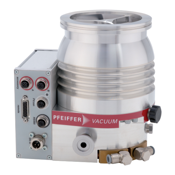
- Page 1 OPERATING INSTRUCTIONS Original HIPACE 300 P Turbopump...
- Page 2 Dear Customer, Thank you for choosing a Pfeiffer Vacuum product. Your new turbopump is designed to support you by its performance, its perfect operation and without interfering your individual application. The name Pfeiffer Vacuum stands for high-quality vacuum technology, a comprehensive and complete range of top-quality products and first-class service.
-
Page 3: Table Of Contents
Table of contents Table of contents About this manual Validity 1.1.1 Related documents 1.1.2 Product variants affected Target group Conventions 1.3.1 Instructions in the text 1.3.2 Pictographs 1.3.3 Stickers on the product 1.3.4 Abbreviations Safety General safety instructions Safety instructions Safety precautions Limits of use of the product Proper use... - Page 4 Operating modes 6.2.1 Operation without operating unit 6.2.2 Operation via multi-function connection "remote" 6.2.3 Operation via connection "E74" 6.2.4 Operation via Pfeiffer Vacuum display and control unit 6.2.5 Operation via field bus Switching on the turbopump Operation monitoring 6.4.1 Operating mode display via LED 6.4.2 Temperature monitoring...
- Page 5 Tbl. 14: Characteristic nominal rotation speeds of the turbopumps........44 Tbl. 15: Troubleshooting turbopumps..................49 Tbl. 16: Overview of the spare parts available for the HiPace 300 P........52 Tbl. 17: Conversion table: Pressure units................54 Tbl. 18: Conversion table: Units for gas throughput.............. 54 Tbl.
- Page 6 Fig. 22: Removing the operating fluid reservoir..............42 Fig. 23: Installing and removing the electronic drive unit TC 400..........44 Fig. 24: Spare parts HiPace 300 P..................52 Fig. 25: HiPace 300 | TC 400 | DN 100 ISO-K..............58 Fig. 26: HiPace 300 | TC 400 | DN 100 ISO-F..............58 Fig.
-
Page 7: About This Manual
Keep the manual for future consultation. 1.1 Validity These operating instructions are for customers of Pfeiffer Vacuum. They describe the function of the designated product and provide the most important information for safe usage of the product. The de- scriptions comply with applicable directives. All information provided in these operating instructions refer to the current development status of the product. -
Page 8: Pictographs
This section describes all the stickers on the product along with their meaning. Rating plate The rating plate of the turbopump is located on the lower part D-35614 Asslar HiPace 300 P Mod. of the vacuum pump. PM P04 710 C... -
Page 9: Abbreviations
Flange: Metal-sealed connector in accordance with ISO 3669 Diameter value (in mm) Direct current Display Control Unit (Pfeiffer Vacuum display and control unit). Nominal diameter as size description Rotation speed value of a vacuum pump (frequency, in rpm or Hz) Process execution Handheld Programming Unit. -
Page 10: Safety
Safety 2 Safety 2.1 General safety instructions This document includes the following four risk levels and one information level. DANGER Imminent danger Indicates a hazardous situation which, if not avoided, will result in death or serious injury. ► Instructions on avoiding the hazardous situation WARNING Possibly imminent danger Indicates a hazardous situation which, if not avoided, could result in death or serious injury. - Page 11 Safety Risks during installation DANGER Danger to life from electric shock Power supply packs that are not specified or are not approved will lead to severest injuries up to death. ► Make sure that the power supply pack meets the requirements for double isolation between mains input voltage and output voltage, in accordance with IEC 61010 and IEC 60950.
- Page 12 Safety WARNING Risk of scalding from suddenly escaping hot cooling water The turbopump water connections are open to both sides. When connecting the cooling water supply, there is a risk of scalding from suddenly escaping, hot cooling water at over pressure. ►...
- Page 13 There is a risk of serious injury, potentially even fatal, and significant equip- ment damage. ► Follow the installation instructions for this turbopump. ► Observe the requirements regarding stability and design of the counter flange. ► Use only original accessories or fixing material approved by Pfeiffer Vacuum for the installation. 13/60...
-
Page 14: Safety Precautions
► Take suitable safety precautions on-site for the compensation of the occurring torques. ► Before installing a vibration compensator, you must first of all contact Pfeiffer Vacuum. WARNING Danger to life from poisoning where toxic process media leak from damaged connections Sudden twisting of the turbopump in the event of a fault causes fittings to accelerate. -
Page 15: Proper Use
Safety Installation altitude max. 5000 m Rel. air humidity max. 80%, at T < 31°C, up to max. 50% at T < 40°C Protection class Excess voltage category Permissible protection class IP54 Degree of contamination Ambient temperature 5 °C to 30 °C with convection cooling with- out gas throughput 5°C to 35°C with air cooling 5°C to 40°C with water cooling... - Page 16 Safety ● Venting with impermissible high venting rates ● Use for pressure generation ● Use in areas with ionizing radiation ● Operation in explosion-hazard areas ● Use in systems in which sporadic loads and vibrations or periodic forces act on the device ●...
-
Page 17: Product Description
Product description 3 Product description 3.1 Function The turbopump forms a compact unit with the electronic drive unit. The Pfeiffer Vacuum power supply packs serve as voltage supply. The feature description "P" designates turbopumps suitable for the process. They are insensitive against dust and corrosive gases. -
Page 18: Drive
ID no. 000021320. 3.3.1 Product types The product designation of Pfeiffer Vacuum turbopumps from the HiPace series is composed of the family name, the size (which is based on the pumping speed of the vacuum pump) and, if required, an additional feature description. -
Page 19: Transportation And Storage
4. Always carry the turbopump with both hands. 5. Remove the protective cover only immediately prior to installation. 4.2 Storage Pfeiffer Vacuum recommends storing the products in their original transport pack- aging. Storing the turbopump 1. Close all flange openings with the original protective caps. -
Page 20: Installation
Installation 5 Installation The installation of the turbopump and its fastening is of outstanding importance. The rotor of the turbo- pump revolves at very high speed. In practice it is not possible to exclude the risk of the rotor touching the stator (e.g. due to the penetration of foreign bodies into the high vacuum connection). The kinetic energy released acts on the housing and on the anchoring of the turbopump within fractions of a sec- ond. -
Page 21: Considering Earthquake Protection
50 kg) Tbl. 5: Requirements for the dimensioning of customer-specific high vacuum connection Important information for correct installation ► Only use the approved mounting kits of Pfeiffer Vacuum for the high vacuum connection of the turbopump. 5.2.2 Considering earthquake protection NOTICE... -
Page 22: Using A Splinter Shield Or Protective Screen
Safety connection, customer-side 5.2.3 Using a splinter shield or protective screen Pfeiffer Vacuum centering rings with splinter shield or protective screen in the high vacuum flange pro- tect the Turbopump against foreign matter from the vacuum chamber. The pumping speed is reduced according to the passage guide values and the size of the high vacuum flange. -
Page 23: Attaching Iso-K Flange Onto Iso-K
Flange connection ISO-K to ISO-F, bracket screws Connection with bracket screw 1. For the connection of the turbopump, use only the approved mounting kits from Pfeiffer Vacuum. 2. Connect the flange with the components of the mounting kit according to the figure. -
Page 24: Fig. 7: Flange Connection Iso-K With Iso-F, Hexagon Head Screw And Tapped Hole
Flange connection ISO-K with ISO-F, hexagon head screw and tapped hole Connection of the hexagon head screw and tapped hole 1. Only use the approved mounting kits of Pfeiffer Vacuum for the connection of the turbopump. 2. Place the collar flange over the high vacuum flange of the turbopump. -
Page 25: Attach Iso-F Flange To Iso-F
Connection of the hexagon head screw and tapped hole 1. Only use the approved mounting kits of Pfeiffer Vacuum for the connection of the turbopump. 2. Attach the turbopump with centering ring to the counter flange according to the figure. -
Page 26: Fastening Cf Flange To Cf-F
Connection of the stud screw and through hole 1. Only use the approved mounting kits of Pfeiffer Vacuum for the connection of the turbopump. 2. Attach the turbopump with collar flange, snap ring and centering ring to the counter flange accord- ing to the figure. -
Page 27: Connecting The Fore-Vacuum Side
Connection of the stud screw and tapped hole 1. For the connection of the turbopump, use only the approved mounting kits from Pfeiffer Vacuum. 2. Screw in the required number of stud screws with the shorter end in the holes on the counter flange. -
Page 28: Cooling Water Connection
1. With rigid pipe connections, include bellows to attenuate external vibrations. 2. Install a fore-vacuum connection with small flange components, e.g. connection elements and pipe components DN 16 ISO-KF from the Pfeiffer Vacuum Components Shop. 3. Implement measures to counteract the backflow of operating fluids or condensate from the fore- vacuum area. -
Page 29: Tbl. 7: Requirements On The Cooling Water Composition
Installation Parameter Cooling water Appearance ● filtered ● mechanically clear ● visually clear ● no turbidity ● no sediment ● free from grease and oil pH value 7 to 9 Carbonate hardness, max. 10 °dH 12.53 °e 17.8 °fH 178 ppm CaC0 Chloride content, max. -
Page 30: Connecting Accessories
1. Observe the installation instructions in the operating instructions for the relevant accessory. 2. Note the existing configuration of existing connections. 3. Use the Pfeiffer Vacuum display and control unit DCU 002, or a DCU with integrated power supply pack. -
Page 31: Connecting The Venting Valve
Installation 5.5.2 Connecting the venting valve A Pfeiffer Vacuum venting valve serves the automatic venting of a turbopump after switching off or in event of a power failure. ● The permissible inlet pressure for venting gas is 1,500 hPa absolute. Connecting the venting valve 1. -
Page 32: Connecting Sealing Gas
The supply is carried out either via a sealing gas valve or a sealing gas throttle with- out control. ● Pfeiffer Vacuum recommends the use of sealing gas from 50 % of the maximum gas throughput. ● The permissible inlet pressure for sealing gas is 1,500 hPa absolute. -
Page 33: Connecting The Electrical Supply
Installation (2x) Fig. 19: Connection of the heating jacket Pump housing Heating relay box Allen head screw "Hot surface" warning sticker Heating jacket Required tools ● Allen key, size 4 or 5 Installing a heating jacket 1. Carefully bend out the heating jacket at the outer clamping strap. 2. -
Page 34: Earthing The Pump
► Do not carry out your own conversions or modifications on the unit. ► Ensure the integration into an Emergency Off safety circuit. 5.6.1 Earthing the pump Pfeiffer Vacuum recommends connecting a suitable grounding cable to discharge applicative interfer- ences. Fig. 20:... -
Page 35: Fig. 21: Connecting The Electronic Drive Unit To A Power Supply Pack
2. Make sure that the power supply pack main switch is off prior to connection. 3. Use a matching connecting cable from the Pfeiffer Vacuum accessories program. 4. Insert the connecting cable into the connection "DCin" on the electronic drive unit and close the bayonet lock. -
Page 36: Operation
Important settings and function-related variables are factory-programmed into the vacuum pump elec- tronic drive unit as parameters. Each parameter has a three-digit number and a description. Parameter- driven operation and control is supported via Pfeiffer Vacuum displays and control units, or externally via RS-485 using Pfeiffer Vacuum protocol. -
Page 37: Operating Modes
Instructions for operation without control panel 1. Use only the approved Pfeiffer Vacuum mating plug with bridges on the connection of the elec- tronic drive unit. 2. Switch on the mains supply of the turbopump only immediately before operation. -
Page 38: Switching On The Turbopump
Operation The following are available: ● Profibus ● EtherCAT ● DeviceNet Instructions for field bus operation ► See the operating manual of the electronic drive unit with corresponding connection panel. 6.3 Switching on the turbopump WARNING Danger of cut injuries from unexpected start up. The use of mating plugs of the electronic drive unit (accessories) enables the automatic run-up of the vacuum pump as soon the power is turned on. -
Page 39: Temperature Monitoring
Operation Symbol LED status Display Meaning without current On, flashing "Pumping station OFF", rotation speed ≤ 60 Green On, inverse flashing "Pumping station ON", set rotation speed not reached On, constant "Pumping station ON", set rotation speed reached On, flashing "Pumping station OFF", speed >... -
Page 40: Venting
General information for fast venting We recommend fast venting of larger volumes in 4 steps. 1. Use a Pfeiffer Vacuum venting valve for the turbopump, or match the valve cross-section to the size of the recipient and maximum venting rate. -
Page 41: Maintenance
5. Change the operating fluid reservoir at least every 4 years. 6. Have Pfeiffer Vacuum Service replace the rotor bearing of the turbopump at least every 4 years. 7. Consult with Pfeiffer Vacuum Service about shorter maintenance intervals for extreme loads or im- pure processes. -
Page 42: Fig. 22: Removing The Operating Fluid Reservoir
► Never use sharp, metallic tools (e.g., tweezers). ► Remove sealing rings by hand only, or with wooden or plastic sticks if necessary. You can find the safety data sheet can in the Pfeiffer Vacuum Download Center. Preparatory work 1. Do not apply any mechanical loads to the electronic drive unit. -
Page 43: Replacing The Electronic Drive Unit
Maintenance – Do not use cleaning agents. Installing the operating fluid reservoir 1. Insert all new Poroplast rods using tweezers. 2. Insert the operating fluid reservoir into the bearing housing with the felt side in the direction of the injection tip. –... -
Page 44: Confirming The Rotation Speed Specification
Tbl. 14: Characteristic nominal rotation speeds of the turbopumps Required aids ● A connected Pfeiffer Vacuum display and control unit. ● Knowledge of the configuration and setting of electronic drive unit operating parameters. Adjusting the nominal rotation speed confirmation The redundant confirmation of the nominal rotation speed of a turbopump is possible by adjusting the [P:777] NomSpdConf parameter in the electronic drive unit. - Page 45 Maintenance 5. Set the parameter [P:777] to the required value of the nominal rotation speed in Hertz. Alternative: A Pfeiffer Vacuum SpeedConfigurator for the one-time immediate setting of parameter [P: 777] is included with the replacement units. 45/60...
-
Page 46: Decommissioning
2. Clean the turbopump externally with a lint-free cloth and a little isopropanol. 3. If necessary, arrange for Pfeiffer Vacuum Service to completely clean the turbopump. 4. Observe the total running time of the turbopump and if necessary, arrange for Pfeiffer Vac- uum Service to replace the bearing. -
Page 47: Disposing Of The Vacuum Pump
Decommissioning 8.3 Disposing of the vacuum pump WARNING Health hazard through poisoning from toxic contaminated components or devices Toxic process media result in contamination of devices or parts of them. During maintenance work, there is a risk to health from contact with these poisonous substances. Illegal disposal of toxic sub- stances causes environmental damage. -
Page 48: Malfunctions
● Electronic drive unit de- 1. Replace the electronic drive unit. fective 2. Contact Pfeiffer Vacuum Service. ● For operation without 1. Connect the connections according to the electron- Pump will not start up; green LED on the electronic drive unit control unit: Pins 1-3 ic drive unit connection diagram. - Page 49 Pump not achieving the ultimate ● Pump is dirty 1. Heat the pump if required. pressure 2. Have it cleaned. 3. Contact Pfeiffer Vacuum Service. ● Vacuum chamber, pipes 1. Carry out leak detection starting from the vacuum or pump leaky chamber.
-
Page 50: Service Solutions From Pfeiffer Vacuum
We are consistently striving to perfect our core competence, service for vacuum components. And our service is far from over once you’ve purchased a product from Pfeiffer Vacuum. It often enough really just begins then. In proven Pfeiffer Vacuum quality, of course. - Page 51 ERKLÄRUNG KONTAMINIERUNG Then send your product to your local Service Center. You will receive a confirmation message/a quotation from Pfeiffer Vacuum. For all service orders, our General Terms and Conditions of Sales and Supply General Terms and Conditions of Repair and Maintenance apply to vacuum equipment and components.
-
Page 52: Spare Parts Hipace 300 P
Operating fluid reservoir PM 203 410 -T incl. Poroplast rods and O- ring Banjo fitting P 4131 007 D Water cooling Tbl. 16: Overview of the spare parts available for the HiPace 300 P 52/60... -
Page 53: Accessories
Accessories 12 Accessories View the line of accessories for Pfeiffer Vacuum turbopumps online at pfeiffer-vac- uum.com. 53/60... -
Page 54: Technical Data And Dimensions
Technical data and dimensions 13 Technical data and dimensions 13.1 General This section describes the basis for the technical data of Pfeiffer Vacuum turbopumps. Technical data Maximum values refer exclusively to the input as a single load. ● Specifications according to PNEUROP committee PN5 ●... - Page 55 Technical data and dimensions Classification HiPace® 300 P HiPace® 300 P HiPace® 300 P Flange (out) DN 16 ISO-KF/G ¼" DN 16 ISO-KF/ DN 16 ISO-KF/ G ¼" G ¼" Ultimate pressure according to < 1 · 10 < 1 · 10 <...
-
Page 56: Tbl. 19: Technical Data For Hipace 300 P | 24 V
Hybrid Hybrid Hybrid Weight 6.4 kg 8.4 kg 6.7 kg Tbl. 19: Technical data for HiPace 300 P | 24 V Classification HiPace® 300 P HiPace® 300 P HiPace® 300 P Order number PM P04 720 PM P04 721 PM P04 722... -
Page 57: Tbl. 20: Technical Data For Hipace 300 P | 48 V
-25 °C – 55 °C -25 °C – 55 °C -25 °C – 55 °C Mounting orientation Bearing Hybrid Hybrid Hybrid Weight 6.4 kg 8.4 kg 6.7 kg Tbl. 20: Technical data for HiPace 300 P | 48 V 57/60... -
Page 58: Dimensions
Technical data and dimensions 13.3 Dimensions Dimensions in mm 18.6 DN 100 ISO-K DN 16 ISO-KF / G1/4" Ø 8 Fig. 25: HiPace 300 | TC 400 | DN 100 ISO-K DN 100 ISO-F 18.6 DN 16 ISO-KF / G1/4" Ø 8 Fig. -
Page 59: Declaration Of Conformity
● Electromagnetic compatibility 2014/30/EU ● Restriction of the use of certain hazardous substances 2011/65/EU The authorized representative for the compilation of technical documents is Mr. Hel- mut Bernhardt, Pfeiffer Vacuum GmbH, Berliner Straße 43, 35614 Aßlar, Germany. Turbopump HiPace 300 P...
Need help?
Do you have a question about the HiPace 300 P and is the answer not in the manual?
Questions and answers