
Related Manuals for Hirschmann GREYHOUND GRS1020


Summary of Contents for Hirschmann GREYHOUND GRS1020
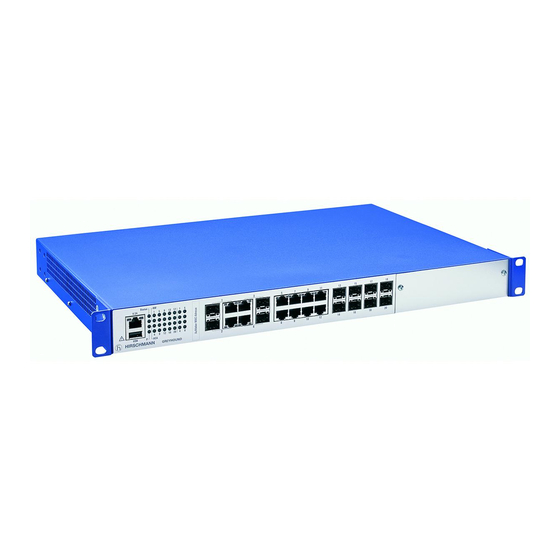
- Page 1 User Manual Installation GREYHOUND Switch GRS1020/1120/1030/1130 GRS 1020 GRS 1030 GRS 1120 GRS 1130 Installation GRS1020/1120/1030/1130 Technical support Release 03 01/2017 https://hirschmann-support.belden.eu.com...
- Page 2 In addition, we refer to the conditions of use specified in the license contract. You can get the latest version of this manual on the Internet at the Hirschmann product site (www.hirschmann.com). Hirschmann Automation and Control GmbH Stuttgarter Str.
-
Page 3: Table Of Contents
Contents Safety instructions About this Manual Legend Description General device description Device name and product code Combination options Device views 1.4.1 Front view 1.4.2 Rear view Power supply 1.5.1 Supply voltage with the characteristic value C 1.5.2 Supply voltage with the characteristic value M Ethernet ports 1.6.1 Gigabit combo port 1.6.2 10/100 Mbit/s twisted pair port... - Page 4 Operating the device Connecting data cables Filling out the inscription label Making basic settings Monitoring the ambient air temperature Maintenance and service Disassembly Removing the device Removing an SFP transceiver (optional) Removing a media module (optional) Technical data Further Support Installation GRS1020/1120/1030/1130 Release 03 01/2017...
-
Page 5: Safety Instructions
Operate the device with undamaged components exclusively. The device is free of any service components. In case of a damaged or malfunctioning the device, turn off the supply voltage and return the device to Hirschmann for inspection. Qualification requirements for personnel ... - Page 6 Supply voltage The supply voltage is electrically isolated from the housing. Every time you connect the electrical conductors, make sure that the following requirements are met: The power supply conforms to overvoltage category I or II. The power supply has an easily accessible disconnecting device (e.g., a switch or a plug).
- Page 7 WARNING ELECTRIC SHOCK Start connecting the electrical wires only if all the above safety requirements are fulfilled. Failure to follow these instructions can result in death, serious injury, or equipment damage. Verify that the electrical installation meets locally or nationally applicable safety regulations.
- Page 8 Device casing WARNING ELECTRIC SHOCK Never insert sharp objects (small screwdrivers, wires, etc.) into the inside of the device. Never insert sharp objects (small screwdrivers, wires, etc.) into the connection terminals for electric conductors, and do not touch the terminals. Install this device solely in a switch cabinet or in an operating site with restricted access, to which maintenance staff have exclusive access.
- Page 9 Operating conditions Operate the device at the specified ambient temperature (temperature of the ambient air at a distance of 2 inches (5 cm) from the device) and at the specified relative humidity exclusively. When you are selecting the installation location, make sure you observe the climatic threshold values specified in the technical data.
- Page 10 Any GREYHOUND-GRS1xxx device Class I, Division 2 Ordinary location, Groups A, B, C, D non-hazardous area, Hazardous Location non-explosive atmosphere Front view THE USB POWER SUPPLY CONTACTS DEPEND ON THE FOLLOWING PARAMETERS: *) 10 μF 10 μH USB pin 4 USB pin 1 Back view THE RELAY TERMINALS DEPEND ON THE...
- Page 11 SUITABLE FOR USE IN CLASS I DIVISION 2 GROUPS A, B ,C ,D HAZARDOUS LOCATIONS, OR NON-HAZARDOUS LOCATIONS ONLY. For use in HAZARDOUS LOCATIONS only allowed for model numbers which are labelled accordingly. National Electrical Code (NEC), NFPA 70, article 501;CEC, Appendix J, Annex J18. WARNING –...
- Page 12 In accordance with the above-named EU directive(s), the EU conformity declaration will be at the disposal of the relevant authorities at the following address: Hirschmann Automation and Control GmbH Stuttgarter Str. 45-51 72654 Neckartenzlingen Germany www.hirschmann.com...
- Page 13 LED or laser components LED or LASER components according to IEC 60825-1 (2014): CLASS 1 LASER PRODUCT CLASS 1 LED PRODUCT FCC note: This device complies with part 15 of the FCC rules. Operation is subject to the following two conditions: (1) this device may not cause harmful interference;...
-
Page 14: About This Manual
About this Manual The “Installation” user manual contains a device description, safety instructions, a description of the display, and the other information that you need to install the device. The documentation for your device is made up of the following documents: ... -
Page 15: Description
Description General device description You can choose from between a wide range of variants. You have the option to set up your device individually based on different criteria: Number of ports Transmission speed Types of connectors Temperature range ... -
Page 16: Device Name And Product Code
The devices provide you with a large range of functions, which the manuals for the operating software inform you about. You will find these manuals as PDF files on the Internet on the Hirschmann product pages (www.hirschmann.com). The Hirschmann network components help you ensure continuous communication across all levels of the company. - Page 17 See table 2 on page 18. 18 ... 19 Customer-specific Hirschmann standard version Hardware configuration S Standard Software configuration E Entry (Hirschmann Standard) 22 ... 23 Software level HiOS Layer 2 Standard 24 ... 28 Software version 04.1. Software-Version 04.1 XX.X.
- Page 18 Application case Certificates and declarations Characteristic value Standard applications EN 60950-1 EN 61131-2 ISA 12.12.01 – Class I, Div. 2 cUL 60950-1 Substation applications IEC 61850-3 IEEE 1613 Navy applications DNV GL Railway applications EN 50121-4 (trackside) Table 2: Assignment: application cases, certificates and declarations, characteristic values a.
- Page 19 Voltage input 24 V ... 48 V 16...17 Approvals and declarations: CE, EN 60950-1, EN 61131-2, FCC Customer-specific version: Hirschmann standard 18...19 Hardware configuration: Standard Software configuration: Entry (Hirschmann Standard) 22...23 Software level: HiOS Layer 2 Standard 24...28 Software version 04.1 - 04.1.
-
Page 20: Combination Options
Combination options Item 1 ... 3 9 ... 12 16 ... 17 18 ... 19 20 22 ... 24 ... Charac- Device Series Position of Data Confi- Tempe- Supply Supply Approvals Custo- Hardware Software Soft- Soft- teristic the ports and rate support gura-... -
Page 21: Device Views
Device views 1.4.1 Front view Grounding screw Connection for the signal contact 16 × RJ45 socket for 10/100 Mbit/s twisted pair connections Cover panel Supply voltage connection 1 alternatively, Supply voltage with the 2-pin terminal block depending on characteristic value C device variant Supply voltage with the ... -
Page 22: Rear View
1.4.2 Rear view USB interface V.24 interface LED display elements Grounding screw Table 6: Back view of device variant GRS1130 Supply voltage connection 1 alternatively, Supply voltage with the 2-pin terminal block depending on characteristic value C device variant ... -
Page 23: Power Supply
Power supply You will find information on the characteristic values here: “Device name and product code” on page 16 1.5.1 Supply voltage with the characteristic value C A 2-pin terminal block is available to supply the device with power. For further information see “Supply voltage with the characteristic value C”... - Page 24 Media type Connection options twisted pair cable Technical standard IEEE 802.3 10BASE-T/100BASE- TX/1000BASE-T Connection type RJ45 Fiber optic cable either Technical standard IEEE 802.3 100BASE-FX Connection type Fast Ethernet SFP transceiver Technical standard IEEE 802.3 1000BASE-SX/LX Connection type 1 Gigabit Ethernet SFP transceiver Table 8: Combo ports: Connection options 10/100/1000 Mbit/s twisted pair port...
-
Page 25: 10/100 Mbit/S Twisted Pair Port
1.6.2 10/100 Mbit/s twisted pair port This port is an RJ45 socket. The 10/100 Mbit/s twisted pair port offers you the ability to connect network components according to the IEEE 802.3 10BASE-T/100BASE-TX standard. This port supports: Autonegotiation Autopolarity ... -
Page 26: Display Elements
Display elements After the supply voltage is set up, the software starts and initializes itself. Afterwards, the device performs a self-test. During this process, various LEDs light up. 1.7.1 Device state These LEDs provide information about conditions which affect the operation of the whole device. -
Page 27: Port Status
Display Color Activity Meaning Storage medium — None ACA storage medium not connected ACA31 Green Lights up ACA storage medium connected Flashes 3 Device writes to/reads from the storage times a period medium Yellow Lights up ACA storage medium inoperative 1.7.2 Port status These LEDs provide port-related information. -
Page 28: Media Module Status
To change to the LED display on the service panel, execute the following commands in the CLI: Change to the privileged EXEC mode. enable Change to the configuration mode. configure Change LED display from port panel to service system port-led-mode panel. -
Page 29: Management Interfaces
Management interfaces 1.8.1 V.24 interface (external management) A serial interface is provided on the RJ45 socket (V.24 interface) for the local connection of an external management station (VT100 terminal or PC with corresponding terminal emulation). This enables you to set up a connection to the Command Line Interface CLI and to the system monitor. -
Page 30: Signal Contact
The USB interface has the following properties: Supplies current of max. 500 mA Voltage not potential-separated Connectors: type A Supports the USB master mode Supports USB 2.0 Figure Operation VCC (VBus) − Data + Data Ground (GND) Table 12: Pin assignment of the USB interface Signal contact... -
Page 31: Installation
Installation The devices have been developed for practical application in a harsh industrial environment. On delivery, the device is ready for operation. Perform the following steps to install and configure the device: Checking the package contents Installing and grounding the device ... - Page 32 CAUTION OVERHEATING OF THE DEVICE When installing the device, ensure that the ventilation slots are not covered. Failure to follow these instructions can result in injury or equipment damage. Mounting in a switch cabinet Note: Install the device in the 19" switch cabinet using sliding or mounting rails.
- Page 33 Y LED LS/D A 6.1 Figure 2: Assembly in a switch cabinet with sliding/mounting rails 1 - GREYHOUND device 2 - sliding/mounting rail 3 - 19" switch cabinet Proceed as follows: Assemble the sliding or mounting rails in the 19" switch cabinet as specified by the manufacturer.
- Page 34 Mounting on a vertical flat surface WARNING FIRE HAZARD Install the device in a fire protected shell if you are mounting it vertically. Failure to follow these instructions can result in death, serious injury, or equipment damage. Use the pre-mounted brackets as shown below. ...
-
Page 35: Installing An Sfp Transceiver (Optional)
Remove the protection cap from the SFP transceiver. Push the SFP transceiver with the lock closed into the slot until it latches Figure 4: F/O SFP transceiver Use only Hirschmann SFP transceivers which are suitable for usage with the device. See “Accessories” on page 54. -
Page 36: Connecting The Terminal Blocks
Connecting the terminal blocks WARNING ELECTRIC SHOCK Connect only a supply voltage that corresponds to the type plate of your device. Never insert sharp objects (small screwdrivers, wires, etc.) into the connection terminals for electric conductors, and do not touch the terminals. Failure to follow these instructions can result in death, serious injury, or equipment damage. -
Page 37: Supply Voltage With The Characteristic Value M
For every supply voltage to be connected, perform the following steps: Remove the power connector from the device. Connect the wires according to the pin assignment on the device with the clamps. Fasten the wires connected by tightening the terminal screws. 2.4.2 Supply voltage with the characteristic value M You will find information on the characteristic values here:... -
Page 38: Signal Contact
WARNING ELECTRIC SHOCK Install this device solely in a switch cabinet or in an operating site with restricted access, to which maintenance staff have exclusive access. Failure to follow these instructions can result in death, serious injury, or equipment damage. For every supply voltage to be connected, perform the following steps: ... -
Page 39: Mounting A Media Module (Optional)
Mounting a media module (optional) Hirschmann supplies the media modules in a ready-to-operate state. By using a media module, you obtain up to 8 additional Fast Ethernet ports. You have the option of mounting the media modules while the device is operating. -
Page 40: Operating The Device
Operating the device Relevant for North America: The torque for tightening the supply voltage terminal block on the device is 4.5 lb-in (0.51 Nm). The torque for tightening the terminal block for the signal contact on the device is 3 lb-in (0.34 Nm). Proceed as follows: ... -
Page 41: Making Basic Settings
Making basic settings Note: Two or more devices configured with the same IP address can cause unpredictable operation of your network. Install and maintain a process that assigns a unique IP address to every device in the network. The IP parameters must be entered when the device is installed for the first time. -
Page 42: Monitoring The Ambient Air Temperature
Monitoring the ambient air temperature Operate the device below the specified maximum ambient air temperature exclusively. See “General technical data” on page 46. The ambient air temperature is the temperature of the air at a distance of 2 in (5 cm) from the device. It depends on the installation conditions of the device, e.g. -
Page 43: Maintenance And Service
Maintenance and service When designing this device, Hirschmann largely avoided using high-wear parts. The parts subject to wear and tear are dimensioned to last longer than the lifetime of the product when it is operated normally. Operate this device according to the specifications. -
Page 44: Disassembly
Disassembly Removing the device WARNING ELECTRIC SHOCK Disconnect the grounding only after disconnecting all other cables. Failure to follow these instructions can result in death, serious injury, or equipment damage. Proceed as follows: To detach the device from the switch cabinet or the wall, remove the screws from the brackets on the device. -
Page 45: Removing A Media Module (Optional)
Removing a media module (optional) Figure 8: Demounting a media module Loosen the screws in the front panel of the media module. Open the lock of the media module by pressing the locking lever outwards (steps 1 and 2). ... -
Page 46: Technical Data
Technical data General technical data Dimensions GRS1020- 17.64 in. × 12.40 in. × 1.73 in. (448 mm × W × H × D 315 mm × 44 mm) GRS1120- (without brackets) GRS1030- GRS1130- Weight GRS1020-16T9 8.16 lb (3.7 kg) Supply voltage GRS1120-16T9 with the... - Page 47 Power supply Nominal voltage DC 24 V ... 48 V Supply voltage Voltage range DC incl. 18 V ... 60 V with the maximum tolerances characteristic Connection type 2-pin terminal block value C Power loss buffer > 10 ms at 20.4 V DC Back-up fuse for each voltage Nominal rating: 6.3 A...
- Page 48 Dimension drawings inch 482,6 465,9 18.3 17.5 10,3 Figure 9: Dimensions of the device variant GRS1030 Installation GRS1020/1120/1030/1130 Release 03 01/2017...
- Page 49 EMC and immunity EMC interference Standard Merchant Navy Railway Substation emission applications applications applications (trackside) Radiated emission EN 55022 Class A Class A Class A Class A DNV GL Guidelines — EMC 1 — — FCC 47 CFR Part 15 Class A Class A Class A...
- Page 50 EMC interference Standard Merchant Navy Railway Substation immunity applications applications applications (trackside) Electrostatic discharge EN 61000-4-2 Contact discharge ± 4 kV ± 6 kV ± 6 kV ± 8 kV IEEE C37.90.3 EN 61000-4-2 Air discharge ± 8 kV ± 8 kV ±...
- Page 51 EMC interference Standard Merchant Navy Railway Substation immunity applications applications applications (trackside) Damped vibration – DC supply connection EN 61000-4-12 line/ground — — — 2.5 kV IEEE C37.90.1 EN 61000-4-12 line/line — — — 1 kV IEEE C37.90.1 Damped oscillation - data line EN 61000-4-12 line/ground —...
- Page 52 Network range Note: The line lengths specified for the transceivers apply for the respective fiber data (fiber attenuation and BLP/dispersion). Product Wave Fiber System Example Fiber code length attenu- for F/O attenu- dispersion M-SFP-... ation line ation length -SX/LC... MM 850 nm 50/125 µm 0-7.5 dB 0-550 m...
- Page 53 Product Wave Fiber System Example Fiber BLP/ code length attenu- for F/O line attenu- dispersion M-FAST- ation length ation SFP-... -MM/LC... MM 1310 nm 50/125 µm 0-8 dB 0-5 km 1.0 dB/km 800 MHz×km -MM/LC... MM 1310 nm 62.5/125 µm 0-11 dB 0-4 km 1.0 dB/km 500 MHz×km...
- Page 54 Scope of delivery Number Article 1 × Device 1 × 2-pin terminal block for signal contact 1 × 3-pin terminal block for the supply voltage (only for device variants featuring supply voltage with the characteristic value M9) 2 × 3-pin terminal block for the supply voltage (only for device variants featuring supply voltage with the characteristic value MM) 1 ×...
- Page 55 Gigabit Ethernet SFP transceiver Order number SFP-GIG-LX/LC EEC 942 196-002 a. You find further information on certifications on the Internet at the Hirschmann product pages (www.hirschmann.com). Bidirectional Gigabit Ethernet SFP transceiver Order number M-SFP-BIDI Type A LX/LC EEC 943 974-001...
- Page 56 Other accessories Order number Terminal cable: RJ45 on USB 942 096-001 3-pin High Voltage Interlock terminal block (50 pcs.) 943 845-008 2-pin Low Voltage Interlock terminal block (50 pcs.) 943 845-010 Bracket for fastening the housing 943 943-001 Dust protection cap (50 pieces) for RJ45 sockets 943 936-001 Dust protection cap (25 pieces) for SFP slot 943 942-001...
- Page 57 If your device has a shipping approval according to DNV GL, you find the approval mark printed on the device label. You will find out whether your device has other shipping approvals on the Hirschmann website under www.hirschmann.com in the product information.
-
Page 58: A Further Support
Further Support Technical Questions For technical questions, please contact any Hirschmann dealer in your area or Hirschmann directly. You will find the addresses of our partners on the Internet at http://www.hirschmann.com. A list of local telephone numbers and email addresses for technical support directly from Hirschmann is available at https://hirschmann-support.belden.eu.com. - Page 59 Installation GRS1020/1120/1030/1130 Release 03 01/2017...
Need help?
Do you have a question about the GREYHOUND GRS1020 and is the answer not in the manual?
Questions and answers