Sign In
Upload
Download
Table of Contents
Contents
Add to my manuals
Delete from my manuals
Share
URL of this page:
HTML Link:
Bookmark this page
Add
Manual will be automatically added to "My Manuals"
Print this page
×
Bookmark added
×
Added to my manuals
Manuals
Brands
Hirschmann Manuals
Switch
PowerMICE MS4128
User manual
Hirschmann PowerMICE MS4128 User Manual
Powermice series industrial ethernet switch
Hide thumbs
1
2
Table Of Contents
3
4
5
6
7
8
9
10
11
12
13
14
15
16
17
18
19
20
21
22
23
24
25
26
27
28
29
30
31
32
33
34
35
36
37
38
39
40
41
42
43
44
45
46
47
48
49
50
51
52
53
54
55
56
57
58
page
of
58
Go
/
58
Contents
Table of Contents
Bookmarks
Table of Contents
User Manual
Table of Contents
Safety Instructions
Supply Voltage
General Safety Instructions
About this Manual
Legend
1 Device Description
Description of the Modules
Powermice Basic Module MS4128
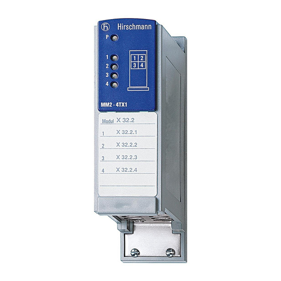
Media Modules
MB-2T Expansion Module
SFP Modules
2 Assembly and Start-Up
Overview of Installation
Installing the Device
Unpacking and Checking
Installing the Media Modules
Filling out and Attaching Labels
Installing the SFP Modules
Adjusting DIP Switch Settings on Basic Module
Adjusting the DIP Switch Settings on the MM20-A8A89999SAHH Media Module
Connecting the MM22-T1T1T1T1 Poe Media Module
Connecting the Terminal Blocks for Supply Voltage and Signal Contact
Installing the Terminal Blocks; Start-Up Procedure
Installing the Device on the DIN Rail, Grounding
Connecting the Data Lines
Aui Connection
Installing the MB-2T Expansion Module
Defining the Meaning of the Display Leds
Display Elements
Device Status
Port Status
Basic Set-Up
Maintenance
Disassembly
3 Technical Data
Dimension Drawing
Order Numbers
Scope of Delivery
A Further Support
Advertisement
Quick Links
1
User Manual
2
Description of the Modules
3
Device Status
4
Port Status
5
Basic Set-Up
Download this manual
User Manual
Installation
Industrial Ethernet Switch
PowerMICE
PowerMICE
Technical support
Document No.: 039654005 Release 01 04/2014
https://hirschmann-support.belden.eu.com
Table of
Contents
Previous
Page
Next
Page
1
2
3
4
5
Advertisement
Table of Contents
Need help?
Do you have a question about the PowerMICE MS4128 and is the answer not in the manual?
Ask a question
Questions and answers
Related Manuals for Hirschmann PowerMICE MS4128
Switch Hirschmann RS20 Reference Manual
Web-based interface industrial ethernet (gigabit) switch (172 pages)
Switch Hirschmann RS20 User Manual
Redundancy configuration industrial ethernet (gigabit) switch (100 pages)
Switch Hirschmann RS20 Reference Manual
Ethernet gigabit switch (572 pages)
Switch Hirschmann RS20 User Manual
(294 pages)
Switch Hirschmann MACH 100 User Manual
Industrial ethernet (gigabit-)switch (76 pages)
Switch Hirschmann RS20 User Manual
Industrial (284 pages)
Switch Hirschmann RS20 Reference Manual
Industrial ethernet (gigabit) switch (204 pages)
Switch Hirschmann RS20 User Manual
Redundancy configuration industrial ethernet (gigabit-)switch (128 pages)
Switch Hirschmann MSP30 User Manual
Mice switch power (58 pages)
Switch Hirschmann MSP30 User Manual
Mice switch power/mice switch media modules (94 pages)
Switch Hirschmann MSM20 User Manual
Mice switch media modules (60 pages)
Switch Hirschmann MSM20 User Manual
Installation mice switch media modules (56 pages)
Switch Hirschmann MSP40 User Manual
Mice switch power/mice switch media modules (94 pages)
Switch Hirschmann MACH 4000 Reference Manual
Web-based interface industrial ethernet (gigabit) switch (286 pages)
Switch Hirschmann MACH 3001 Description And Operating Instructions
Lan (12 pages)
Switch Hirschmann MACH4000 Series User Manual
Modular industrial ethernet backbone switch (68 pages)
This manual is also suitable for:
Powermice mm2-4tx1
Powermice mm2-4fxm3
Powermice mm2-2fxm3/2tx
Powermice mm2-2fxm2
Powermice mm2-2fxs2
Powermice mm3-4tx5
...
Show all
Powermice mm3-4flm4
Powermice mm3-1fxm2/3tx1
Powermice mm2-4tx1-eec
Powermice mm3-2fxm4/2tx1
Powermice mm3-2fxm2/2tx1
Powermice mm3-2fxm2/2tx1-eec
Powermice mm3-4fxm4
Powermice mm3-4fxm2
Powermice mm3-1fxs2/3tx1-eec
Powermice mm3-1fxs2/3tx1
Powermice mm2-2flm4
Powermice mm3-2fxs2/2tx1
Powermice mm3-4fxs2
Powermice mm3-1fxl2/3tx1
Powermice mm22-t1t1t1t1
Powermice mm4-4tx/sfp
Powermice mm4-2tx/sfp
Powermice mb-2t
Powermice mm20-z6z6z6z6
Table of Contents
Print
Rename the bookmark
Delete bookmark?
Delete from my manuals?
Login
Sign In
OR
Sign in with Facebook
Sign in with Google
Upload manual
Upload from disk
Upload from URL


Need help?
Do you have a question about the PowerMICE MS4128 and is the answer not in the manual?
Questions and answers