Sign In
Upload
Download
Table of Contents
Contents
Add to my manuals
Delete from my manuals
Share
URL of this page:
HTML Link:
Bookmark this page
Add
Manual will be automatically added to "My Manuals"
Print this page
×
Bookmark added
×
Added to my manuals
Manuals
Brands
Hirschmann Manuals
Switch
MACH102 Series
User manual
Hirschmann MACH102 Series User Manual
Industrial ethernet workgroup switch
Hide thumbs
1
2
Table Of Contents
3
4
5
6
7
8
9
10
11
12
13
14
15
16
17
18
19
20
21
22
23
24
25
26
27
28
29
30
31
32
33
34
35
36
37
38
39
40
41
42
43
44
45
46
47
48
page
of
48
Go
/
48
Contents
Table of Contents
Bookmarks
Table of Contents
User Manual
Table of Contents
Safety Instructions
General Safety Instructions
About this Manual
Legend
1 Description
Description of the Device Variants
MACH102 Basic Devices
MACH102 Media Modules
SFP Modules
2 Assembly and Start-Up
Installing the Device
Unpacking and Checking the Content of the Package
Installing Media Modules
Installing the SFP Modules
FAULT" Signal Contact
Dimension Drawings
Installing the Device and Grounding
Mounting on the Wall
Supply Voltage
Operating the Device
Connecting Network Cables
Display Elements
Basic Set-Up
Usb Interface
Disassembly
3 Technical Data
Order Numbers
Scope of Delivery
A Further Support
Advertisement
Quick Links
1
User Manual
2
Mach102 Basic Devices
3
Operating the Device
4
Connecting Network Cables
5
Basic Set-Up
Download this manual
User Manual
Installation
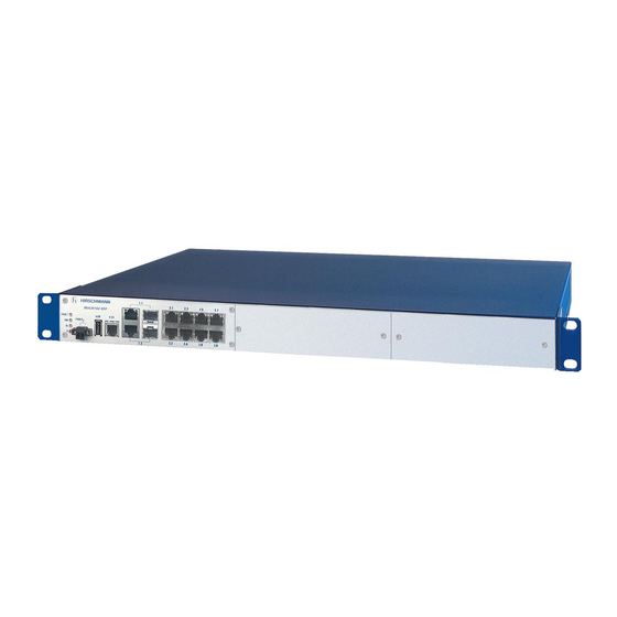
Industrial Ethernet Workgroup Switch
MACH102 Family
MACH 102-8TP-F
MACH 102-24TP-F
MACH 102-8TP + M1-8TP-RJ45 + M1-8MM-SXC
MACH 102-8TP + M1-8SM-SXC + M1-8SFP
Installation MACH102
Release 06 09/2014
Technical support
https://hirschmann-support.belden.eu.com
Table of
Contents
Previous
Page
Next
Page
1
2
3
4
5
Advertisement
Table of Contents
Need help?
Do you have a question about the MACH102 Series and is the answer not in the manual?
Ask a question
Questions and answers
Related Manuals for Hirschmann MACH102 Series
Switch Hirschmann MACH104-20TX-F User Manual
Industrial ethernet workgroup switch full gigabit family (38 pages)
Switch Hirschmann RS20 User Manual
Redundancy configuration industrial ethernet (gigabit) switch (100 pages)
Switch Hirschmann RS20 Reference Manual
Ethernet gigabit switch (572 pages)
Switch Hirschmann RS20 User Manual
(294 pages)
Switch Hirschmann MACH 100 User Manual
Industrial ethernet (gigabit-)switch (76 pages)
Switch Hirschmann RS20 User Manual
Industrial (284 pages)
Switch Hirschmann RS20 User Manual
Redundancy configuration industrial ethernet (gigabit-)switch (128 pages)
Switch Hirschmann MACH 4000 Reference Manual
Web-based interface industrial ethernet (gigabit) switch (286 pages)
Switch Hirschmann PowerMICE User Manual
Basic configuration industrial ethernet (gigabit) switch (308 pages)
Switch Hirschmann Power MICE User Manual
Routing configuration industrial ethernet (gigabit) switch (95 pages)
Switch Hirschmann MACH100 Reference Manual
Ethernet gigabit switch (572 pages)
Switch Hirschmann MACH4000 Series User Manual
Modular industrial ethernet backbone switch (68 pages)
Switch Hirschmann DRAGON MACH4000 series User Manual
Modular industrial gigabit ethernet backbone switch (76 pages)
Switch Hirschmann MACH4002-48G User Manual
Modular industrial ethernet backbone switch (68 pages)
Switch Hirschmann MACH1000 Series User Manual
Industrial ethernet ruggedized switch (70 pages)
Switch Hirschmann MACH1020 User Manual
Industrial ethernet ruggedized switch (70 pages)
This manual is also suitable for:
Mach 102-8tp-fr
Mach 102-24tp-fr
Mach 102-8tp-r
Mach 102-8tp-f
Mach 102-24tp-f
Mach 102-8tp
Table of Contents
Save PDF
Print
Rename the bookmark
Delete bookmark?
Delete from my manuals?
Login
Sign In
OR
Sign in with Facebook
Sign in with Google
Upload manual
Upload from disk
Upload from URL


Need help?
Do you have a question about the MACH102 Series and is the answer not in the manual?
Questions and answers