
Related Manuals for Clarke C2MS210MP


Summary of Contents for Clarke C2MS210MP
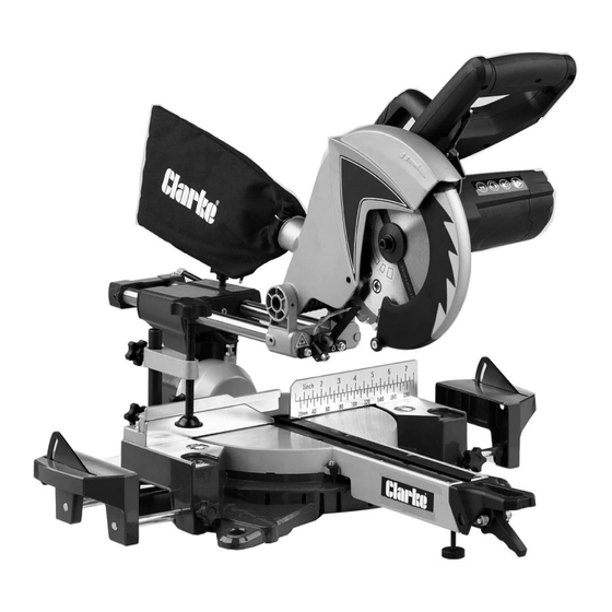
- Page 1 SLIDING COMPOUND MITRE SAW MODEL NO: C2MS210MP/C2MS250MP PART NO: 6461545/6461550 OPERATION & MAINTENANCE INSTRUCTIONS ORIGINAL INSTRUCTIONS GC0119 - ISS 1...
-
Page 2: Environmental Protection
GUARANTEE This CLARKE product is guaranteed against faulty manufacture for a period of 12 months from the date of purchase. Please keep your receipt as proof of purchase. -
Page 3: Safety Warnings
SAFETY WARNINGS WORK AREA 1. Keep the work area clean and well lit. Cluttered and dark areas invite accidents. 2. Do not operate power tools in explosive atmospheres, such as in the presence of flammable liquids, gases or dust. Power tools create sparks which may ignite the dust or fumes. -
Page 4: Additional Safety Rules For Mitre Saws
4. Remove any adjusting key or wrench before turning the power tool on. A wrench or a key left attached to a rotating part of the power tool may result in personal injury. 5. Do not overreach. Keep proper footing and balance at all times. This enables better control of the power tool in unexpected situations. - Page 5 20. When possible, always mount the saw on to a bench or plywood base which is then clamped to a bench or mount the machine to a purpose built mitre saw stand available from your local Clarke dealer. Parts & Service: 020 8988 7400 / E-mail: Parts@clarkeinternational.com or Service@clarkeinternational.com...
-
Page 6: Safety Symbols
SAFETY SYMBOLS The following safety symbols are to be found on the product. Wear eye protection Wear ear defenders Do not put your hand near the blade Read instruction manual before use Laser Radiation, Class 2 Laser: Do not stare into the beam. -
Page 7: Electrical Connections
ELECTRICAL CONNECTIONS WARNING! READ THESE ELECTRICAL SAFETY INSTRUCTIONS THOROUGHLY BEFORE CONNECTING THE PRODUCT TO THE MAINS SUPPLY. Before switching the product on, make sure that the voltage of your electricity supply is the same as that indicated on the rating plate. This product is designed to operate on 230V AC 50Hz. - Page 8 OVERVIEW Parts & Service: 020 8988 7400 / E-mail: Parts@clarkeinternational.com or Service@clarkeinternational.com...
-
Page 9: Before Use
1 x Dust Collection Bag 2 x Workpiece Supports 216 mm Diameter 40 Tooth Cutting 255 mm Diameter 48 Tooth Cutting Blade fitted to the C2MS210MP Blade fitted to the C2MS250MP BENCH MOUNTING Holes are provided in all four feet to facilitate bench mounting. -
Page 10: Setting The Work Supports
SETTING THE WORK SUPPORTS 1. Loosen the work support locking screws. 2. With the saw upside down, slide the work support guide rods through the holes in the base of the saw and secure with the spring clips. 3. Set the saw upright. 4. -
Page 11: Releasing/Locking The Saw Head
RELEASING/LOCKING THE SAW HEAD RELEASING 1. Press down slightly on the operating handle. • Pull out the head locking pin to release the arm for cutting and twist it 90 to remain locked in the ‘out’ position. LOCKING 2. Press down on the head while pushing the guard release to the side to release the safety catch and lower the head. -
Page 12: Check And Adjust The Mitre Pointer
ADJUSTMENTS WARNING: MAKE SURE THAT THE SAW IS SWITCHED OFF AND UNPLUGGED FROM THE MAINS SUPPLY BEFORE PERFORMING ANY ADJUSTMENTS. CHECK AND ADJUST THE MITRE POINTER The saw can be set in a number of positions as determined by the mitre locking mechanism but the pointer should read zero when making straight cuts and remain true for other angles selected. - Page 13 4. Place a set square on the table and up against the blade. • Do not touch the extended tips of the blade teeth with the square. Lower the blade so as to present as much blade surface as possible to the set square. If adjustment is required, proceed as follows: 5.
-
Page 14: Operation
OPERATION Always observe the safety instructions and applicable regulations. BODY AND HAND POSITION Proper positioning of your body and hands when operating the saw will make cutting easier and safer. • Never place your hands near the cutting area or blade. •... -
Page 15: Different Saw Cuts
DIFFERENT SAW CUTS VERTICAL STRAIGHT CROSS CUT 1. Release the table mitre lock by lifting the latch handle and pressing the locking handle down. 2. Rotate the table so that the pointer lines up with the 0° position on the scale. 3. -
Page 16: Performing A Sliding Cut
PERFORMING A SLIDING CUT The guide rail allows cutting larger workpieces using an out-down-back sliding motion. 1. Release the slide rail lock. 2. Switch the saw on and pull the saw head towards you (1). 3. Lower the saw blade (2) into the workpiece and push the head back (3) to complete the cut. -
Page 17: Mitre / Bevel Cuts
BEVEL CUTS Bevel angles can be set from 45° left to vertical and can be cut with the mitre arm set between zero and a maximum of 45° mitre position right or left. 1. Loosen the bevel clamp handle and set the bevel to the desired angle. -
Page 18: Groove Cutting
GROOVE CUTTING Your saw is equipped with a thumbscrew adjuster to provide for groove cutting. 1. Firstly, determine the depth of your groove and subtract this value from the thickness of your workpiece. This will give you the height above the table surface at which the saw blade must be set. -
Page 19: The Laser Guide
THE LASER GUIDE Your saw is fitted with a laser guide to assist with accurate cutting. Switch the laser on/off using the on/ off switch. Parts & Service: 020 8988 7400 / E-mail: Parts@clarkeinternational.com or Service@clarkeinternational.com... -
Page 20: Maintenance
MAINTENANCE WARNING: MAKE SURE THAT THE SAW IS SWITCHED OFF AND UNPLUGGED FROM THE POWER SUPPLY BEFORE FITTING OR REMOVING THE BLADE. WARNING: THE BLADE MUST BE RATED TO AT LEAST 7000 RPM. CHANGING THE SAW BLADE Only install the correct saw blade. Do not use excessively worn blades. The maximum rotation speed of the saw must not exceed that of the saw blade. - Page 21 • The blade must be rated to at least 7000 rpm. • Spare blades are available from your local Clarke dealer. 7. Replace the outer disc and washer and secure with the centre screw, remembering the screw has a LEFT HAND THREAD (turn it ANTICLOCKWISE to tighten).
-
Page 22: Technical Specifications
TECHNICAL SPECIFICATIONS C2MS210MP C2MS250MP Power Supply 230V @ 50Hz Electrical Insulation Class IP rating IP20 Blade Diameter 216 mm 255 mm Blade bore 30 mm Max. blade thickness (Kerf) 2.8 mm Number of Teeth Max. No Load Speed 7000 rpm... -
Page 23: Declaration Of Conformity
DECLARATION OF CONFORMITY Parts & Service: 020 8988 7400 / E-mail: Parts@clarkeinternational.com or Service@clarkeinternational.com...
Need help?
Do you have a question about the C2MS210MP and is the answer not in the manual?
Questions and answers