
Related Manuals for Clarke CLS400


Summary of Contents for Clarke CLS400
- Page 1 400MM LOGSAW MODEL NO: CLS400 PART NO: 3401995 ASSEMBLY & OPERATING INSTRUCTIONS GC1015...
-
Page 2: Environmental Recycling Policy
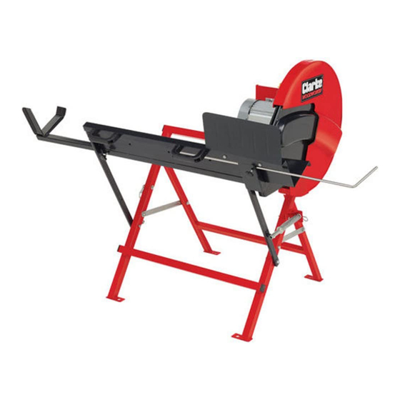
INTRODUCTION Thank you for purchasing this CLARKE Log Saw. The CLARKE CLS400 is a single speed circular saw directly driven by the motor. It is equipped with a log cradle which holds the log steady while working and has a hinged guard which retracts as the log is pushed against the saw. -
Page 3: Safety Warnings
SAFETY WARNINGS WORK AREA 1. Keep the work area clean and well lit. Cluttered and dark areas invite accidents. 2. Do not operate power tools in explosive atmospheres such as in the presence of flammable liquids, gasses or dust. Power tools create sparks which may ignite dust or fumes. - Page 4 3. Do not over-reach. Keep your proper footing and balance at all times. This enables better control of the power tool in unexpected situations. 4. Concentrate on the job in hand, no matter how trivial it may seem. Be aware that accidents are caused by carelessness due to familiarity. 5.
-
Page 5: Precautions Specific To Circular Saws
intended function. Any damage should be properly repaired or the part replaced. If in doubt, DO NOT use the machine. Consult your local dealer SERVICING 1. When necessary, have your power tools serviced or repaired by a qualified person using identical replacement parts. This will ensure that the safety of the power tool is maintained. -
Page 6: Changing Blades
Ensure the blade is secure before use. 2. Use the appropriate saw blade for this saw. Correct blades are available from your Clarke dealer as listed on page 18. 3. Only use saw blades in good working condition. Discard and replace cracked or bent saw blades. -
Page 7: Safety Symbols & Pictograms
SAFETY SYMBOLS & PICTOGRAMS Please read all of the safety and operating instructions carefully before using this product. The following safety symbols may be found on the product. Parts & Service: 020 8988 7400 / E-mail: Parts@clarkeinternational.com or Service@clarkeinternational.com... -
Page 8: Electrical Connections
ELECTRICAL CONNECTIONS WARNING: READ THESE ELECTRICAL SAFETY INSTRUCTIONS THOROUGHLY BEFORE CONNECTING THE PRODUCT TO THE MAINS SUPPLY. Connect the mains lead to a standard, 230 Volt (50Hz) electrical supply through an approved 13 amp BS1363 plug, or a suitably fused isolator switch. If the plug has to be changed because it is not suitable for your socket or because of damage, it must be removed and a replacement fitted, following the wiring instructions shown below. - Page 9 OVERVIEW ESCRIPTION ESCRIPTION Log Support Yoke Log Cradle Support Stand 13 Connecting Chain Fixed Guard 14 Securing Knob Moving Guard Other items supplied Loose Log Stop Bar Guard Support Bracket Protective Plate Saw Blade Return Spring Assembly Blade Securing Discs (x2) Motor Stand c/w motor Open Wrench Handle (x2)
-
Page 10: Installing The Fixed Guard
ASSEMBLY When unpacking, check for damage or shortages etc. Any found should be reported to your CLARKE dealer where the product was originally purchased. ASSEMBLING THE SWITCH & STANDS PARTS REQUIRED: • ON/OFF Switch:- 4 x M4 x 55 mm screws & 4 x M4 washers •... -
Page 11: Installing The Saw Blade
1. Attach the Fixed Guard Support Bracket to the motor mounting plate using 2 x M8 bolts, locknuts & washers as shown in Fig 3. 2. Secure the Fixed Guard to the Motor Stand and fixed Guard Support Bracket with the four flat washers and locknuts as in Fig 4. - Page 12 • Do not use a blade with no markings, but if they have become worn away during previous use, inspect the blade and note the direction of the teeth. Only use Clarke supplied replacement blades. • Never use cracked, blunt or otherwise damaged blades.
-
Page 13: Assembling The Log Cradle
ASSEMBLING THE LOG CRADLE PARTS REQUIRED: • Return Spring Mounting Bracket:- 1 x 40mm bolt, locknut, 2 x washers. • Return Spring Rod:- 1 x M6 x 40 bolt, locknut, 2 x 6 mm washers, 1 x R-Clip & 1 x Spring. •... - Page 14 4. Bolt the return spring mounting bracket to the support arm using the 40mm bolt. 5. Fit the Return Spring Assembly to the cradle support arm using a the 40mm bolt, at the same time, feeding the spring onto the rod before passing the rod through the return spring mounting bracket.
-
Page 15: Mounting The Saw To The Floor
MOUNTING THE SAW TO THE FLOOR The foot of each leg is provided with a bolt hole for fixing the log saw to a suitably level floor or platform. Choose a suitable position close to a convenient power supply and bolt or screw the stand securely in position. (fixings not supplied) OPERATION BEFORE STARTING WORK... - Page 16 3. If logs of equal length are required, set the log stop bar to the required distance and lock in position with the securing knob. 4. Lift the top cover of the On/Off switch in order to press the green On button and switch the saw on.
-
Page 17: Changing The Saw Blade
• Never try to re-start the saw if the blade becomes jammed in the workpiece. Switch off and release the jammed log first. CHANGING THE SAW BLADE CAUTION: ONLY USE SAW BLADES WITH THE CORRECT FITTING AS SUPPLIED. ALWAYS ENSURE THE SAW IS DISCONNECTED FROM THE POWER SUPPLY BEFORE INSTALLING/REMOVING THE BLADE. -
Page 18: Maintenance
CAUTION: INSTALLING THE BLADE THE WRONG WAY ROUND WILL RESULT IN DAMAGE TO THE BLADE. NOTE: Replacement blades are available from your CLARKE dealer as Part No 3401993. MAINTENANCE Always inspect the saw before use and ensure it is in top condition. -
Page 19: Fault Finding
Return to your Clark dealer for repair. Burns showing on Incorrect or blunt saw Replace blade with the the cut timber. blade. correct Clarke replacement. Check and tighten blade as necessary. Parts & Service: 020 8988 7400 / E-mail: Parts@clarkeinternational.com or Service@clarkeinternational.com... -
Page 20: Specification
SPECIFICATION Model Number CLS400 Product Dimensions: (L x W x H) 961 x 885 x 1020 mm Weight 36.5 kg Max Cutting Length 1500 mm Cutting Capacity (min/max dia) 30-135 mm Operating Voltage 230V / 50Hz Fuse Rating Motor Power... -
Page 21: Parts List
PARTS LIST ESCRIPTION ESCRIPTION On/off Switch 40mm bolt Screw M4 x 55mm Fixed Guard Support Bracket Washer Fixed Blade Guard Plastic Guard Wear Strips Inner Retaining Disc Protective Plate Saw Blade Screw Locking Knob Outer Retaining Disc X-head m/c screw Flat Washer Support Stand Blade Retaining Bolt... -
Page 22: Component Parts
COMPONENT PARTS Parts & Service: 020 8988 7400 / E-mail: Parts@clarkeinternational.com or Service@clarkeinternational.com... -
Page 23: Declaration Of Conformity
DECLARATION OF CONFORMITY Parts & Service: 020 8988 7400 / E-mail: Parts@clarkeinternational.com or Service@clarkeinternational.com...
Need help?
Do you have a question about the CLS400 and is the answer not in the manual?
Questions and answers