
Related Manuals for AMX CTC-1402


Summary of Contents for AMX CTC-1402
- Page 1 USER MANUAL VERSION: V1.0.0 CTC-1402 Connectivity and Transport Kit - Conferencing A V FOR AN IT WORLD ®...
-
Page 2: Important Safety Instructions
COPYRIGHT NOTICE AMX© 2018, all rights reserved. No part of this publication may be reproduced, stored in a retrieval system, or transmitted, in any form or by any means, electronic, mechanical, photocopying, recording, or otherwise, without the prior written permission of AMX. Copyright protection claimed... - Page 3 Anyone performing field maintenance on AMX equipment should use an appropriate ESD field service kit complete with at least a dissipative work mat with a ground cord and a UL listed adjustable wrist strap with another ground cord.
-
Page 4: Table Of Contents
Access the Web Interface ..................29 Web Interface Introduction ..................30 Refresh ........................30 Factory Default ......................30 Reboot ........................30 Upgrade Status ......................31 LOGOUT ........................31 Firmware VERSION ....................31 Auto Switch: ......................31 Key Lock ........................31 User Manual - CTC-1402... - Page 5 TELNET/SSH Access ....................37 TELNET Account ......................37 SSH Account ......................37 Firmware Upgrade ......................38 Before Starting ......................38 Transferring KIT Files....................38 Troubleshooting ........................ 40 API Command Set ......................41 NetLinx Commands ....................42 Telnet/SSH Commands ..................... 50 User Manual - CTC-1402...
-
Page 6: Overview
Overview The CTC-1402 is a 4K 6x Multi-format Inputs Extender Switch with USB extension and includes a scaler for CTC-1402 The transmitter and receiver kit offers six video inputs shared between both devices for HDMI, Display Port, VGA plus analog audio in and USB-C video signals. -
Page 7: Specifications
VIC = 49, 720 x 480p 119.88/120 Hz 16:9 VGA Input Resolution supported: Up to 1920 x 1200 @ 60Hz Input Video Level 0.5-1.0 V p-p Maximum Pixel Clock 600 MHz Output 1 x HDBT OUT User Manual - CTC-1402... - Page 8 Video Impedance 100 Ω Audio Format Sup- PCM 2.0 ported General Operating 0°C to 50°C (32°F to 125.6°F) Temperature Storage Temperature -10°C to 60°C (14°F to 140°F) Humidity 5% to 85%, non-condensing Surge Protection Voltage: ±1 kV User Manual - CTC-1402...
- Page 9 Note: Straight-through category cables wired to T568B standard recommended. Cable Type Range Supported Video HDMI Input/Output:15m/50ft 1080p@60Hz, 24bpp Input/ Output: 10m/33ft 4K@30Hz 4:4:4 Input/Output: 5m/16ft 4K@60Hz, 4:4:4 Shielded Cat 6a/7 100m/330ft 1080p@60Hz 80m/ 262 ft 4K@30Hz, 4:4:4 4K@60Hz, 4:2:0 4K@30Hz, 4:4:4 User Manual - CTC-1402...
-
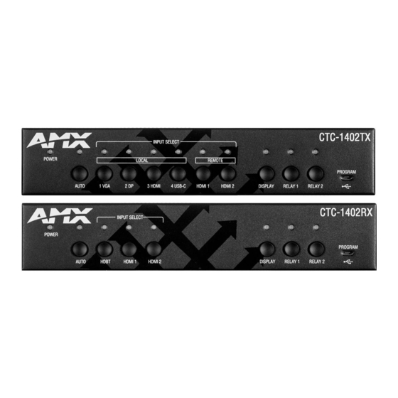
Page 10: Transmitter Front Panel Description
Transmitter Front Panel Description Name Description On: The CTC-1402 TX is powered on. POWER LED Off: The CTC-1402 TX is powered off. (Green) Auto Switch Button: Press to enable/disable auto switching function. Auto LED (Blue): LED is located on the top of the button. - Page 11 Relay 2 Button: Press to set the screen open. LED (Green): LED is located on the top of the button. Relay 2 Short press the button, LED blinks 1 time and extinguishes after finishing the operation. User Manual - CTC-1402...
-
Page 12: Transmitter Rear Panel Description
Connect to the CTC-1402 receiver via a Cat 5e/6/7 cable. RESET When the CTC-1402 TX is powered on, use a pointed stylus to hold down the RESET button for 3 seconds or more, then release, the unit will reboot and restore to its factory defaults. -
Page 13: Receiver Front Panel Description
Receiver Front Panel Description Name Description On: The CTC-1402 RX is powered on. POWER LED Off: The CTC-1402 RX is powered off. (Green) Auto Auto Switch Button: Press to Enable/Disable auto switching function. LED: LED is located on the top of the button. -
Page 14: Receiver Rear Panel Description
Connect to an IR emitter cable for emitting remote signal from TX. RESET When CTC-1402 RX is powered on, use a pointed stylus to hold down the RESET button for 3 seconds or more, then release, the unit will reboot and restore to its factory defaults. -
Page 15: Pinout Information
The following figures show the pinouts of the Phoenix Connectors. RS232 Connects to an RS232-enabled device with the 3-pole, 3.5mm captive screw connectors. Wire as shown below: RELAY Connects to a projector screen with the 3-pole, 3.5mm captive screw connectors. Wire as shown below:. User Manual - CTC-1402... -
Page 16: Audio Out
Audio Out Connect to an audio system, such as an amplifier, with the 3-pole, 3.5mm captive screw connector. Wire as shown below: User Manual - CTC-1402... -
Page 17: Installation
The bracket is attached to the enclosure as shown. Repeat steps 1-2 for the other side of the unit. Attach the brackets to a surface or suitable location with user supplied screws. Repeat steps 1~4 to install the receiver. User Manual - CTC-1402... -
Page 18: Wiring
(1-2). Send commands to RS232-C via NetLinx Studio. Connect power to the TX and RX. Power on all input sources and displays. Note: When power is restored, the CTC-1402 will automatically switch to the source selected before power was restored. User Manual - CTC-1402... -
Page 19: Osd
Hold and Press the HDMI 1 and HDMI 2 buttons on the front panel of RX for at least 3 seconds. The IP address of the CTC-1402 will display on the upper right of the connected display’s screen for 15s and then disappear. -
Page 20: Input Source Switching
Press the AUTO Button (ensure AUTO LED is off) or the specific input button (in red frames above) to enable Manual Switching. In Manual Switching mode: When the input port with no source is selected, CTC-1402 will output no signal; If the Power is cycled, on the CTC-1402, the Manual Switching function will remain enabled. Note: •... -
Page 21: Usb Control
HDMI IN 3 source on TX is selected: TX HDMI IN 3 and TX HOST 2 is in a group. Only when HDMI IN 3 is selected, USB devices can be connected to the PC which is connected to USB HOST 2. User Manual - CTC-1402... - Page 22 RX HDMI IN 1 and RX HOST 1 are in a group. Only if the RX HDMI IN1 is selected, the USB devices can be connected to the PC which is connected to RX USB HOST 1. User Manual - CTC-1402...
- Page 23 The CTC-1402 kit supports 1 external USB Hub connected to either the TX or RX Device Port. Devices which present themselves as USB hub such as AMX Acendo Vibe will count as 1 external USB Hub. USB Device Ports support power to connected devices not to exceed .5A per USB device port.
-
Page 24: Netlinx Studio Control
NetLinx Studio Control Controlling the CTC-1402 through NetLinx studio via Ethernet port. Device Number and Ports The physical ports of the product can be mapped to NetLinx studio as follows: Transmitter: Port 1: RS-232-P Port 2: RS-232-C Port 4: IR RX... - Page 25 After configuring each port respectively, control commands can be sent to the device. User Manual - CTC-1402...
-
Page 26: Send Commands To Control A Device
Choose the device you want to control, right click, then choose TELNET Window->Launch TELNET window via NetLinx Studio, enter the Telnet window, input the Telnet API in this window to control the device. Note: For API Commands, see the section API Command Set User Manual - CTC-1402... - Page 27 If “Launch TELNET Window via User Defined Program” is selected, it may be require to enable Telnet as follows: Go to Start/Control Panel/Programs and Features; On the left, select “Turn Windows features On or Off”; Select the check-boxes Telnet Client and Telnet Server, and click “OK”. User Manual - CTC-1402...
-
Page 28: Web Ui Control
Web UI Control Choose the device to be controlled, right click, then choose Web Control Page->Launch Web Control Page via Default Browser, enter the Web UI Control Page. User Manual - CTC-1402... -
Page 29: Web Ui Control
Web UI Control The Web UI designed for the CTC-1402 allows basic controls and advanced settings of the device. The Web UI page can be accessed through NetLinx Studio. Access the Web Interface To get access to Web UI: Connect your PC and the LAN port of the CTC-1402 to the same local area network. -
Page 30: Web Interface Introduction
Click the button, a window pops up. Click “OK” to take effect. Reboot Click to reboot the device. Click the button, a window pops up. Click “OK” to take effect. User Manual - CTC-1402... -
Page 31: Upgrade Status
OFF: The panel buttons are active for switching the sources and displays. HDCP In this column, users can Enable/Disable the HDCP of TX HDMI, USB-C, RX HDMI 1, and RX HDMI 2 ports. • ON: Input ports support HDCP. • OFF: Input ports do not support HDCP. User Manual - CTC-1402... -
Page 32: Edid
POWER ON: Enter the RS232 command to turn on the projector and screen, then click the “SAVE” button to take effect. • POWER OFF: Enter the RS232 command to turn off the projector and screen, then click the “SAVE” button to take effect. • APPLY: Click “APPLY” to take effect. User Manual - CTC-1402... -
Page 33: Relay
In this column, users are able to set Relay On/Off and the Relay Mode: Latch or Momentary. RELAY CONTROLLER: Click to raise the projector screen, and click to drop the projector screen down. Latch: Level triggered. Momentary: Pulse triggered. The delay time can be set (1~10 seconds). User Manual - CTC-1402... -
Page 34: Audio Volume
MANUAL: Click to set the output resolution to Manual mode. In Manual mode, click the down arrow to select a specific output resolution as required. APPLY: Click to set the output resolution to the desired setting. User Manual - CTC-1402... -
Page 35: Network
DHCP: When enabled, the IP address of the CTC-1402 will be assigned automatically by the connected DHCP server. • Static: When the CTC-1402 fails to obtain or detect an IP address from the network it is connected to, select “Static” to set up the IP address manually. -
Page 36: System
Click “APPLY” for the settings to take effect. Login Password In this column, the Login Password can be changed. Input the old password in “OLD PASSWORD” box. Input the new password in “NEW PASSWORD” box. Click “APPLY” for the settings take effect. User Manual - CTC-1402... -
Page 37: Telnet/Ssh Access
SSH Account is used to configure the user name and password of the account. For SSH Account, the default user name is admin, the default password is password. Note: Reboot the device for setting changes to take effect. APPLY: Click “APPLY”, for reboot to take effect. User Manual - CTC-1402... -
Page 38: Firmware Upgrade
Verify the CTC-1402 unit is powered ON. Launch NetLinx Studio and open the Online Tree. Bind the target device to the integrated Master: select and right-click the CTC-1402: from the context sensitive menu, select “Network Bind/Unbind Device” (be sure the check box is selected), click “OK”. - Page 39 Click “Send” to send the file to NetLinx Master and upgrade the firmware on the CTC-1402. Click web UI to check progress of the firmware upgrade. The device will restart automatically. Do not power cycle. Note: • The upgrade process will last 1 hour.
-
Page 40: Troubleshooting
Troubleshooting Power: Ensure all devices are powered on. Indicator: Ensure all LED indicators of the CTC-1402 are normal according to the user manual. Devices: Ensure picture can be shown normally when directly connecting a source a display device. Cable: Plug the HDMI/Cat X cable in and out or connect a different HDMI/Cat X cable. Ensure the specific cable length is within the available transmission range according to the Specifications Section. -
Page 41: Api Command Set
USB-C IN4 HOST 1 HOST2 USB device RS-232C RS-232P Audio in-p IR RX HDBT OUT HDBT IN HDMI IN1 HDMI IN2 HDMI OUT Audio out(de-embedding) HOST1 HOST2 RELAY1 RELAY2 IR IN USB device Audio out-p RS232-C RS232-P User Manual - CTC-1402... -
Page 42: Netlinx Commands
SEND_COMMAND SWITCHER,”’CI2OALL’” “’CI<input>O<output>’” Return: Return: SWITCH-I2,OALL SWITCH-I#,OALL Description: Description: Switches HDMI IN1 to Outputs I#: #={1 ~ 7} 1: VGA- IN; 2: DP_IN; 3: TX_HDMI_IN; 4: USB-C_IN; 5: RX_HDBT_IN; 6: RX_HDMI IN1; 7: RX_HDMI_IN2; <output> {ALL} User Manual - CTC-1402... - Page 43 Return: Return: CEC_DISP_POWER-<ON|OFF> CEC_DISP_POWER-OFF Description: Execute a display control off CEC_DISP_AUTO Command: Command: To define the display SEND_COMMAND <DEV>,”’CEC_DISP_ SEND_COMMAND <DEV>,”’CEC_DISP_AUTO- control automatically AUTO-<ON|OFF>’” OFF’” Return: Return: ‘CEC_DISP_AUTO-<ON|OFF> CEC_DISP_AUTO-OFF Description: Define the display control automatically off User Manual - CTC-1402...
- Page 44 VGA_IN; DP_IN; TX_HDMI_IN; USB-C_IN; RX_HDMI_IN1; RX_HDMI_IN2; <resolution> For VGA Input 1920x1200,60 1920x1080,60 1680x1050,60 1600x900,60 1440x900,60 1360x768,60 1280x768,60 1024x768,60 For HDMI Input 3840x2160,60 3840x2160,30 1920x1080,60 1280x720,60 1920x1200,60 1680x1050,60 1600x1200,60 1600x900,60 1440x900,60 1400x1050,60 1366x768,60 1280x1024,60 1280x960,60 1024x768,60 COPY User Manual - CTC-1402...
- Page 45 TX_HDMI_IN; USB-C_IN; RX_HDMI IN1; RX_HDMI_IN2; Command: Command: ?VIDIN_HDCP To Get Input HDCP SEND_COMMAND <DEV>,”’?VIDIN_HDCP’” SEND_COMMAND VIDEO_INPUT_3,”’?VIDIN_ Compliant Status HDCP’” Return: VIDIN_HDCP-<ENABLE|DISABLE> Return: VIDIN_HDCP-ENABLE Description: Description: Input port: HDMI IN2 HDCP Compliant. TX_HDMI_IN; USB-C_IN; RX_HDMI IN1; RX_HDMI_IN2; User Manual - CTC-1402...
- Page 46 4096x2160,60 4096x2160,30 … … 1024x768,60 800x600,60 Command: Command: REBOOT To cause a warm reboot SEND_COMMAND <DEV>, “’REBOOT’” SEND_COMMAND 5002:1:0, “’REBOOT’” Return: Return: REBOOT SEND_COMMAND 5002:1:0, “’REBOOT’” Description: Description: Cause a warm reboot. Cause a warm reboot. User Manual - CTC-1402...
- Page 47 Set Video out color space is RGB Device will reboot to take effect. Command: Command: ?VIDOUT_RGB Gets the video color SEND_COMMAND <DEV>, “’?VIDOUT_RGB’” SEND_COMMAND SWITCHER,”’?VIDOUT_RGB’” space for the video output port Return: Return: VIDOUT_RGB-<ENABLE|DISABLE> VIDOUT_RGB-DISABLE Description: Video out color space is YUV User Manual - CTC-1402...
- Page 48 Audio min is 0 AUDOUT_VOLUME Command: Command: Sets the audio vol for SEND_COMMAND <DEV>, “’AUDOUT_ SEND_COMMAND AUDOUT_VOLUME_1, the audio output port VOLUME-<VALUE>’” “’AUDOUT_VOLUME-50’” Return: Return: AUDOUT_VOLUME-<VALUE> AUDOUT_VOLUME-50 Description: Description: <value> = {0~100} Set Audio vol is 50 User Manual - CTC-1402...
- Page 49 115200, 76800, 57600, 38400, 19200, 9600, 4800, 2400, 1200, 600, 300, 150. parity = N (none), O (odd), E (even), M (mark), S (space) data = 8 data bits stop = 1 or 2 stop bits User Manual - CTC-1402...
-
Page 50: Telnet/Ssh Commands
--- Enter New Values or just hit Enter to keep current settings --- Enter IP Address 192.168.2.201 192.168.2.202 Enter Netmask 255.255.240.0 255.255.255.0 --- New settings --- IP Address 192.168.2.202 Netmask 255.255.255.0 Would you like to save the new settings? Y/N -> y New settings were saved. User Manual - CTC-1402... - Page 51 Enable all system debug messages info Enable info system log level warning Enable warning system log level error Enable error system log level Disable system log output to terminal session Example: msg on reboot >reboot Reboot the device. User Manual - CTC-1402...
- Page 52 System Number: Master Ip/URL Master Port: 1319 set telnet >set telnet username Set telnet service login username username Enter Telnet new username Would you like to set this username (y/n) (please set telnet password) Changed && Saved User Manual - CTC-1402...
- Page 53 >set ssh password Set ssh service login password password Enter ssh new password password pass Would you like to set this password (y/n) Changed && Saved (you should reboot this device that make your setting active) User Manual - CTC-1402...
- Page 54 About AMX by HARMAN Founded in 1982 and acquired by HARMAN in 2014, AMX® is dedicated to providing AV solutions for an IT World. AMX solves the complexity of managing technology with reliable, consistent and scalable systems comprising control, video switching and distribution, digital signage and technology management. AMX systems are deployed worldwide in conference rooms, classrooms, network operation/command centers, homes, hotels, entertainment venues and broadcast facilities, among others.
Need help?
Do you have a question about the CTC-1402 and is the answer not in the manual?
Questions and answers