Advertisement
Quick Links
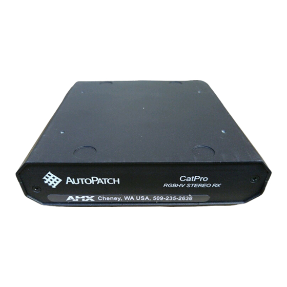
Overview
CatPro RGBHV+Stereo Transmitter (TX) and Receiver (RX) Modules work together or
work in conjunction with CatPro RGBHV+Stereo boards on an AMX AutoPatch
Distribution Matrix. This guide contains complete information for stand-alone use.
For use with a distribution matrix, see the distribution matrix's instruction manual on
the AMX AutoPatch CD or visit www.amx.com.
Specifications
General Specifications – TX (FG1010-45) & RX (FG1010-48)
Approvals
CE, UL, cUL
Signal Types
RGBHV & stereo audio, unbalanced
Maximum Resolution
1600x1200 (4:3) and 1920x1080p (16:9) @ 60 Hz up to 1000 ft.
(305 m)*
Supported Cable Types
CAT-5, CAT-5e, CAT-6, CAT-6e, STP
Power Consumption
12 V to 24 V DC @ 6 Watts
(max.) & Connector
2.1 mm DC power jack
Humidity
0 to 90% non-condensing
Operational Temperature
32° to 110° F (0° to 43° C)
Dimensions
5.22 in. (13.26 cm) depth
5.82 in. (14.78 cm) width
1.42 in. (3.61 cm) height w/out feet
Weight
Approximately 1.5 lb. (0.68 kg)
* When used with an AutoPatch Distribution Matrix, overall cable length cannot exceed 1,000 ft. (305 m).
Specifications – TX (FG1010-45)
RGB In
Signal Level Range:
+0.75 V to -0.3 V
Impedance:
75 ohms
Return Loss:
<-35 dB @ 5 MHz
RGB Local Out
Signal Level Range:
+0.75 V to -0.3 V
Impedance:
75 ohms
SNR:
>65 dB.
Sync In
Impedance:
510 ohms
Polarity:
Active high or low
Sync Local Out
Signal Level:
Low = 0 V, High = +5 V
Polarity:
Active high or low
Audio In
Signal Levels (max.):
+8 dBu
Impedance:
2 kohms
Audio Local Out
Signal Levels (max.):
+8 dBu
(unity gain)
Frequency Response:
<+/-0.35 dB, 20 Hz to 20 kHz
THD+N:
<0.04%, 1 kHz, -10 dBu to +4 dBu
SNR:
>105 dB, 20 Hz to 20 kHz, Vin = +4 dBu
Impedance:
<5 ohms
Connectors
RGBHV In:
1 Female HD-15
RGBHV Local Out:
1 Female HD-15
Stereo Audio In:
1 Female 3.5 mm mini-stereo jack
Stereo Audio Local Out:
1 Female 3.5 mm mini-stereo jack
RGBHV+Stereo Out:
1 Female RJ-45
Specifications – RX (FG1010-48)
RGB Out (at 1000 ft.)
Signal Level Range:
+0.75 V to -0.3 V typical
Impedance:
75 ohms
SNR:
>50 dB
Skew Adjustment:
0 to 62 ns in 2 ns increments on R, G, & B channels
Sync Out
Signal Levels:
Low = 0 V, High = +5 V
Polarity:
Active high or low
Audio Out (at 1000 ft.)
Signal Levels (max.):
+8 dBu
Volume Control Range:
Mute to +6 dB
Frequency Response:
<+/-0.2 dB, 20 Hz to 20 kHz
THD+N:
<0.04%, 1 kHz, -10 dBu to +4 dBu
SNR:
>105 dB, 20 Hz to 20 kHz, Vin = +4 dBu
Impedance:
<5 ohms
Connectors
RGBHV+Stereo In:
1 Female RJ-45
RGBHV Out:
1 Female HD-15
Stereo Audio Out:
1 Pluggable 3.5 mm terminal block
AutoPatch CatPro RGBHV+Stereo Mod
(skew-free STP not recommended)
(terminated)
(terminated)
(unterminated)
(follows input polarity)
(terminated, user adjustable with gain & peak)
(user adjustable)
(unterminated)
(follows input polarity)
(user adjustable)
Module Installation
Note: The modules shown have audio connectors. They are also available without audio.
Important: Always use a UL approved power source. Check the power source's
documentation for information specific to that power source.
To attach source device connectors & power to the TX Module:
Audio
Power
FIG. 1
Attach source device connectors & power to TX
1.
Insert the audio mini-jack (3.5 mm) and the HD-15 connector into the Audio In
and the Video In connectors.
2.
Insert the RJ-45 connector into the UTP/STP Out receptacle.
3.
Plug the power cord* into the power jack and into the power source.
4.
Optional – To use the Local Out option, insert the audio mini-jack and the HD-15
connector into the Local Out connectors.
* If you use the (optional) AutoPatch wall transformer, the side of the wire with the
white stripe is positive and the other side is ground.
To attach destination device connectors & power to the RX Module:
Gain Peak
Power
RJ-45
FIG. 2
Attach destination device connectors & power to RX
1.
Insert the HD-15 connector and wire the audio connector (unbalanced).
2.
Insert the RJ-45 connector into the UTP/STP In receptacle.
3.
Plug the power cord* into the power jack and into the power source.
4.
If the destination display needs adjusting, see the "Adjusting the Picture" topic.
TX & RX HD-15 Pinouts
HD-15 connectors on TX and RX Modules use the pinouts in FIG. 3.
FIG. 3
HD-15 TX In and TX & RX Out connector pinouts
Note: 55 mA supplied on output pin 9; power draw not to exceed 50 mA per port.
System Setup
A typical setup using CatPro RGBHV+Stereo TX and RX Modules is illustrated in
FIG. 4. The signals are sent to a monitor with speakers at a distance, as well as to a
local monitor with speakers.
TX #FG1010-45
Source PC
Local Monitor
with Speakers
FIG. 4
Typical system setup using CatPro Modules
Quick Start Guide
RJ-45
HD-15
Adjust (Skew & Volume)
Audio Wiring
HD-15
Audio
Destination Monitor
with Speakers
Up to 1000 ft. (305 m)
RX #FG1010-48
ules
Advertisement

Related Manuals for AMX CAT-5 RGBHV RX


Summary of Contents for AMX CAT-5 RGBHV RX
-
Page 1: Module Installation
Overview CatPro RGBHV+Stereo Transmitter (TX) and Receiver (RX) Modules work together or work in conjunction with CatPro RGBHV+Stereo boards on an AMX AutoPatch Distribution Matrix. This guide contains complete information for stand-alone use. For use with a distribution matrix, see the distribution matrix’s instruction manual on the AMX AutoPatch CD or visit www.amx.com. -
Page 2: Troubleshooting
©2008 AMX. All rights reserved. AMX and the AMX logo are registered trademarks of AMX. AMX reserves the right to alter specifications without notice at any time. 3000 RESEARCH DRIVE, RICHARDSON, TX 75082 • 800.222.0193 • fax 469.624.7153 • technical support 800.932.6993 • www.amx.com Troubleshooting LED Blinks Red &...
Need help?
Do you have a question about the CAT-5 RGBHV RX and is the answer not in the manual?
Questions and answers