
Related Manuals for AMX AXU-MSP8


Summary of Contents for AMX AXU-MSP8
- Page 1 $;80063 8QL0RXQW 0LQL06RIWZLUH 3DQHO 6HULHV DQG $;00063065 ,QVWUXFWLRQ 0DQXDO :LUHG &RQWURO 3DQHOV...
- Page 2 AMX dealer. Consumers should inquire from selling dealer as to the nature and extent of the dealer’s warranty, if any. AMX is not liable for any damages caused by its products or for the failure of its products to perform, including any lost profits, lost savings, incidental damages, or consequential damages.
-
Page 3: Table Of Contents
Table of Contents Introduction ................1 Overview Features Front Panels Rear Panels AXCESS Programming ............5 Overview Push Displays Pushbutton LEDs Bargraph Programming Bargraph Modes Bargraph Mode Commands LED Illumination Level Commands Installation ................9 Overview Wall, Podium, and Rack Mounting Procedures OLDesign Software Program .......... - Page 4 Table of Contents AXU-MSP Series and AXM-MSP32...
-
Page 5: Introduction
AXCESS system. The AXU-MSP series include the AXU-MSP8, AXU-MSP16, AXU-MSP24, AXU-MSP32. The AXM-MSP32, which contains the same pushbutton and bargraph configuration as the AXU-MSP32, can be mounted into a 19-inch rack. -
Page 6: Features
Features Each panel connects to an AMX AXCESS control system using an AXlink cable. The panel pushbuttons perform specific operations according to the AXCESS software and cards in your control system. Each panel comes with a custom engraved overlay and pushbutton configuration to optimize usability. The number of pushbuttons can vary depending on the number of operations the panel must perform. - Page 7 Engraved Figure 3 Pushbutton 9 overlay Pushbutton 5 AXU-MSP24 panel Pushbutton 13 Pushbutton 1 Pushbutton 17 Pushbutton 21 Bargraph 1 Bargraph 2 Bargraph 3 Pushbutton 13 Pushbutton 17 Figure 4 Engraved overlay Pushbutton 9 Pushbutton 21 AXU-MSP32 panel Pushbutton 25 Pushbutton 5 Pushbutton 1 Pushbutton 29...
-
Page 8: Rear Panels
The MSP rear panels contain the AXlink bus connector, AXlink LED, and the SIP switch that is used to set the panel's device number. Figure 6 shows the back panel component configurations. AXU-MSP16 AXU-MSP24 Figure 6 MSP rear panels AXU-MSP3 2/AXM-MSP32 AXU-MSP8 Introduction AXU-MSP Series and AXM-MSP32... -
Page 9: Axcess Programming
AXCESS Programming Overview MSP pushbuttons can be programmed individually or in any combination as single devices or in a group arrangement. Bargraph LEDs can be programmed to interact with panel pushbuttons. They can be programmed to work with any one of the pushbuttons, or as independent display indicators. -
Page 10: Bargraph Programming
Bargraph Programming To program LED bargraphs, commands similar to those in the following example are included in the AXCESS software program. DEFINE_DEVICE Figure 7 VOL = 12 (* VOLUME CONTROL CARD DEVICE 12 *) Sample AXCESS software MSP = 128 (* MINI SOFTWIRE PANEL DEVICE 128 *) program DEFINE_VARIABLE... -
Page 11: Bargraph Mode Commands
Bargraph Mode Commands Figure 9 lists the commands to program a bargraph. 'BMODE <Bargraph 1 - 3> <Bargraph mode 0 - 9>' Figure 9 Bargraph mode options Mode Description Mode Description Bargraph mode options Normal bar mode (default). Inverse special bar mode. Normal dot mode. - Page 12 AXCESS Programming AXU-MSP Series and AXM-MSP32...
-
Page 13: Installation
Installation Overview This section describes how to install the MSP. Wall, Podium, and Rack Mounting Procedures Install the wall, podium, or rack-mount MSP as follows: Cut out the wall or podium according to the mounting dimensions provided in the Specifications section of this guide. Go to step 2 if the panel will be installed into a wall box or rack. - Page 14 Turn the captive screws clockwise to secure the wires. Connect the AXlink connector to the panel. Locate the green AXlink LED on the rear side of the panel. If the green LED flashes once per second, the panel is communicating properly with the AXCESS system.
-
Page 15: Oldesign Software Program
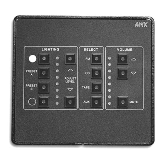
This section gives an overview of the tool to use to program the MSP. Features The AMX OLDesign software program is a Windows-based design tool that you can use to create panel overlays, pushbutton names, and pushbutton operation descriptions. The operation descriptions are used when the panel and AXCESS operating software is programmed. - Page 16 Figure 14 Sample AXU-MSP8 overlay design OLDesign Software Program AXU-MSP Series and AXM-MSP32...
-
Page 17: Specifications
Specifications Overview Figure 15 shows the AXU-MSP8 cutout dimensions, and Figure 16 lists the specifications. Figure 17 shows the AXU-MSP16 cutout dimensions, and Figure 18 lists the specifications. Figure 19 shows the AXU-MSP24 cutout dimensions, and Figure 20 lists the specifications. Figure 21 shows the AXU-MSP32 cutout dimensions, and Figure 22 lists the specifications. - Page 18 Figure 17 AXU-MSP16 cutout dimensions Figure 18 AXU-MSP16 specifications AXU-MSP16 specifications Pushbuttons Up to 16 black, gray, and/or white pushbuttons in a four-by-four matrix. Bargraphs Two one-by-eight LED bargraphs. Power 12 VDC for AXlink 91 mA maximum per panel. Connector 4-pin captive wire compression connector.
- Page 19 Figure 19 AXU-MSP24 mounting dimensions Figure 20 AXU-MSP24 specifications AXU-MSP24 specifications Pushbuttons Up to 24 black, gray, and/or white pushbuttons in a eight-by-four matrix. Bargraphs Three one-by-eight LED bargraphs. Power 12 VDC for AXlink 100 mA maximum per panel. Connector 4-pin captive wire compression connector.
- Page 20 Figure 21 AXU-MSP32 mounting dimensions Figure 22 AXU-MSP32 specifications AXU-MSP32 specifications Pushbuttons Up to 32 black, gray, and/or white pushbuttons in a four-by-four matrix. Bargraphs Three one-by-eight LED bargraphs. 12 VDC for AXlink Power 110 mA maximum per panel. 4-pin captive wire compression connector. Connector Metal with black matte finish Enclosure...
- Page 21 Figure 23 19.00 (482.6 MM) AXM-MSP32 rack mount 3.50 (88.9 MM) Figure 24 AXM-MSP32 rack-mount specifications AXM-MSP32 rack-mount Pushbuttons Up to 32 black, gray, and/or white pushbuttons in a four-by-four matrix. specifications Bargraphs Three one-by-eight LED bargraphs. Power 12 VDC for AXlink 110 mA maximum per panel.
- Page 22 Specifications AXU-MSP Series and AXM-MSP32...
-
Page 23: Technical Support
Technical Support Overview Prior to calling AMX for assistance, check your AXlink, power, and cable connections, and the integrity of your software operating system. Reload the software to see if something in the program is causing the problem. If the problem is not resolved, reload the program from a new copy of your master disk. - Page 24 035-004-1051 12/97 © 1997 AMX Corporation AMX reserves the right to alter specifications without notice at any time. AMX and the AMX 11995 Forestgate Drive logo are registered trademarks of AMX Corporation. All other trademarks contained in this Dallas, Texas 75243 document are the properties of their respective owners.
Need help?
Do you have a question about the AXU-MSP8 and is the answer not in the manual?
Questions and answers