
Related Manuals for DFI HU968


Summary of Contents for DFI HU968
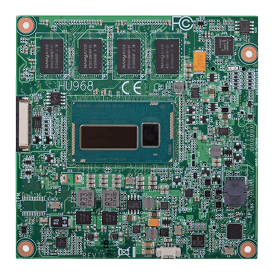
- Page 1 HU968 COM Express Compact Module User’s Manual A31800414 Chapter 1 Introduction www.dfi .com...
-
Page 2: Copyright
Copyright FCC and DOC Statement on Class B This publication contains information that is protected by copyright. No part of it may be re- This equipment has been tested and found to comply with the limits for a Class B digital produced in any form or by any means or used to make any transformation/adaptation without device, pursuant to Part 15 of the FCC rules. -
Page 3: Table Of Contents
COM Express Connectors ................13 COM Express connectors Signal Discription ..........15 Standby Power LED ................... 22 Cooling Option .................... 22 Installing HU968 onto a Carrier Board ..........23 Installing the COM Express Debug Card ..........26 Chapter 1 Introduction www.dfi .com... -
Page 4: About This Manual
About this Manual Static Electricity Precautions An electronic file of this manual is included in the CD. To view the user’s manual in the CD, It is quite easy to inadvertently damage your PC, system board, components or devices even insert the CD into a CD-ROM drive. -
Page 5: About The Package
About the Package The package contains the following items. If any of these items are missing or damaged, please contact your dealer or sales representative for assistance. • One HU968 board • One QR (Quick Reference) • One DVD Optional Items •... -
Page 6: Chapter 1 - Introduction
Chapter 1 Chapter 1 - Introduction Specifications Expansion • Supports 2 USB 3.0 interfaces ® Processor • 4th generation Intel Core processors • Supports 8 USB 2.0 interfaces ® Interfaces 4650U: Intel Core i7-4650U, 4M Cache, up to 3.3 GHz, 15W •... -
Page 7: Features
Chapter 1 Features • Watchdog Timer The Watchdog Timer function allows your application to regularly “clear” the system at the set time interval. If the system hangs or fails to function, it will reset at the set time interval so that your system will continue to operate. -
Page 8: Chapter 2 - Concept
Chapter 2 - Concept COM Express Module Standards The figure below shows the dimensions of the different types of COM Express modules. HU968 is a COM Express Compact module. The dimension is 95mm x 95mm. Common for all Form Factors Extended only... -
Page 9: Specification Comparison Table
Chapter 2 Specification Comparison Table The table below shows the COM Express standard specifications and the corresponding specifications supported on the HU968 module. COM Express Module Base DFI HU968 COM Express Module Base DFI HU968 Specification Type 6 Type 6... -
Page 10: Chapter 3 - Hardware Installation
Chapter 3 Chapter 3 - Hardware Installation Block Diagram Board Layout LVDS Port (Dual Channel) eDP to LVDS VR12.6 TPM (optional) (Vcore) R.G.B DDI Port 2 DP to VGA BGA 1168 DDI Port 2 (Opt. share with DP to VGA) (Opt. -
Page 11: Mechanical Diagram
Chapter 3 Mechanical Diagram HU968 Module HU968 Module with Heat Sink 53.00 95.00 95.00 91.00 91.00 Top View 4.00 4.00 0.00 Heat sink Heatspreader Module PCB Bottom View Standoff 18.00 6.00 Side View of the Module with Heat Sink and Carrier Board 0.00... -
Page 12: System Memory
Chapter 3 Important: System Memory Electrostatic discharge (ESD) can damage your board, processor, disk drives, add-in boards, and other components. Perform installation procedures at an ESD workstation only. If such a station is not available, you can provide some ESD protection by wear- ing an antistatic wrist strap and attaching it to a metal part of the system chassis. -
Page 13: Connectors
Chapter 3 Connectors COM Express Connectors The COM Express connectors are used to interface the HU968 COM Express board to a carrier CPU Fan Connector board. Connect the COM Express connectors (located on the solder side of the board) to the COM Express connectors on the carrier board. - Page 14 Chapter 3 COM Express Connectors Row A Row B Row A Row B Row C Row D Row C Row D GND (FIXED) GND (FIXED) PCIE_TX4- PCIE_RX4- GND (FIXED) GND (FIXED) PEG_RX1- PEG_TX1- GBE0_MDI3- GBE0_ACT# GPO2 TYPE1# TYPE2# GBE0_MDI3+ LPC_FRAME# PCIE_TX3+ PCIE_RX3+ USB_SSRX0-...
-
Page 15: Com Express Connectors Signal Discription
Output from the Module I/O Bi-directional input / output signal OD Open drain output AC97/HDA Signals Descriptions Signal Pin# Module Pin Type Pwr Rail /Tolerance HU968 Carrier Board Description AC/HAD_RST# O CMOS 3.3V Suspend/3.3V Connect to CODEC pin 11 RESET# Reset output to CODEC, active low. - Page 16 Chapter 3 PCI Express Lanes Signals Descriptions Signal Pin# Module Pin Type Pwr Rail /Tolerance HU968 Carrier Board Description PCIE_TX5+ AC Coupling capacitor O PCIE AC coupled on Module Connect to PCIE device or slot PCI Express Differential Transmit Pairs 5...
- Page 17 Chapter 3 PEG Signals Descriptions Signal Pin# Module Pin Type Pwr Rail /Tolerance HU968 Carrier Board Description PEG_TX14+ O PCIE AC coupled on Module PCI Express Graphics transmit differential pairs 14 PEG_TX14- PEG_RX14+ I PCIE AC coupled off Module PCI Express Graphics receive differential pairs 14...
- Page 18 Chapter 3 DDI Signals Descriptions Signal Pin# Module Pin Type Pwr Rail /Tolerance HU968 Carrier Board Description DDI3_PAIR0+ 0 /S O PCIE AC coupled off Module DDI 3 Pair 0 differential pairs DDI3_PAIR0- DDI3_PAIR1+ O PCIE AC coupled off Module...
- Page 19 Chapter 3 LVDS Signals Descriptions Signal Pin# Module Pin Type Pwr Rail /Tolerance HU968 Carrier Board Description Connect to LVDS connector LVDS Channel A differential pairs LVDS_A0+ O LVDS LVDS Ther LVDS flat panel differential pairs (LVDS_A[0:3]+/-, LVDS_B[0:3]+/-. LVDS_A_CK+/-, LVDS_A0- LVDS_B_CK+/-) shall have 100 terminations across the pairs at the destination.
- Page 20 Chapter 3 VGA Signals Descriptions Signal Pin# Module Pin Type Pwr Rail /Tolerance HU968 Carrier Board Description VGA_RED O Analog Analog PD 150 to GND PD 150R,connect to VGA connector with EMI filter & ESD protect component. Red for monitor. Analog output...
- Page 21 Chapter 3 Power and System Management Signals Descriptions Signal Pin# Module Pin Type Pwr Rail /Tolerance HU968 Carrier Board Description THRM# I CMOS 3.3V / 3.3V PU 10K to 3.3V Input from off-Module temp sensor indicating an over-temp situation. THRMTRIP# O CMOS 3.3V / 3.3V...
-
Page 22: Standby Power Led
Bottom View of the Heat Sink • “1” denotes the location of the thermal pad designed to contact the corresponding components that are on HU968. Important: Remove the plastic covering from the thermal pads prior to mounting the heat sink onto HU968. -
Page 23: Installing Hu968 Onto A Carrier Board
The carrier board (COM331-B) used in this section is for reference purpose only and may not resemble your carrier board. These illustrations are mainly to guide you on how to install HU968 onto the carrier board of your choice. • To download COM331-B datasheet and manual 1. - Page 24 Chapter 3 6. Grasping HU968 by its edges, position it on top of the carrier board with its mounting 7. Press HU968 down firmly until it is completely seated on the COM Express connectors of holes aligned with the bolts on the carrier board. This will also align the COM Express the carrier board.
- Page 25 Chapter 3 8. Verify that the module is firmly seated onto the COM Express connectors of the carrier 9. Use the provided mounting screws to secure HU968 with heat sink to the carrier board board. and then connect the cooling fan’s cable to the fan connector on HU968. The photo below shows the locations of the long mounting screws.
-
Page 26: Installing The Com Express Debug Card
Chapter 3 Installing the COM Express Debug Card 2. Connect the COMe-DEBUG card to COMe-LINK1 via a cable. COMe-DEBUG Note: The system board used in the following illustrations may not resemble the actual board. These illustrations are for reference only. Code Review 80 Port Display Control... - Page 27 Chapter 3 3. Fasten bolts with mounting screws through mounting holes to be fixed in place. 5. Grasp HU968 by its edges to press it down on the top of the COMe-LINK1 debug card. Mounting screws HU968 COMe-LINK1 Bolts 4. Use the provided bolts to fix the COMe-LINK1 debug card onto the carrier board.
- Page 28 Chapter 3 7. Use the long mounting screws to secure the heat sink on the top of the HU968 and the COMe-LINK1 debug card and connect the cooling fan’s cable to the fan connector on HU968. The photo below shows the locations of long mounting screws.
-
Page 29: Chapter 4 - Bios Setup
Chapter 4 Chapter 4 - BIOS Setup Legends Overview KEYs Function The BIOS is a program that takes care of the basic level of communication between the CPU Right and Left Arrows Moves the highlight left or right to select a and peripherals. -
Page 30: Ami Bios Setup Utility
Chapter 4 AMI BIOS Setup Utility Advanced Main The Advanced menu allows you to configure your system for basic operation. Some entries are defaults required by the system board, while others, if enabled, will improve the performance of your system or let you set some features according to your preference. The Main menu is the first screen that you will see when you enter the BIOS Setup Utility. - Page 31 Chapter 4 ACPI Settings Trusted Computing This section is used to configure ACPI settings. This section configures settings relevant to Trusted Computing innovations. Aptio Setup Utility - Copyright (C) 2012 American Megatrends, Inc. Aptio Setup Utility - Copyright (C) 2012 American Megatrends, Inc. Advanced Advanced ACPI Settings...
- Page 32 Chapter 4 PC Health Status TPM State This section displays the hardware health monitor. Enable or disable the security device. Note: Aptio Setup Utility - Copyright (C) 2012 American Megatrends, Inc. Your computer will reboot during restarting in order to change the device state. Advanced System Hardware Monitor Enable/Disable CPU...
- Page 33 Chapter 4 CPU Configuration SATA Configuration This section is used to configure the CPU. It will also display the detection of CPU information. This section is used to configure settings of SATA devices. Aptio Setup Utility - Copyright (C) 2012 American Megatrends, Inc. Aptio Setup Utility - Copyright (C) 2012 American Megatrends, Inc.
- Page 34 Chapter 4 Intel(R) Rapid Start Technology AMT Configuration This section is used to enable or disable the Intel Rapid Start Technology. This section configures parameters of Active Management Technology. Aptio Setup Utility - Copyright (C) 2012 American Megatrends, Inc. Aptio Setup Utility - Copyright (C) 2012 American Megatrends, Inc. Advanced Advanced Intel(R) Rapid Start Technology...
- Page 35 Chapter 4 USB Configuration PCH-FW Configuration This section is used to configure parameters of the USB device. This section is used to configure parameters of the Management Engine Technology. Aptio Setup Utility - Copyright (C) 2012 American Megatrends, Inc. Aptio Setup Utility - Copyright (C) 2012 American Megatrends, Inc. Advanced Advanced Enables Legacy USB...
- Page 36 Chapter 4 Network Stack Ipv4 PXE Support This section is used to enable or disable UEFI network stack. When enabled, Ipv4 PXE boot supports. When disabled, Ipv4 PXE boot option will not be created. Ipv6 PXE Support Aptio Setup Utility - Copyright (C) 2012 American Megatrends, Inc. Advanced When enabled, Ipv6 PXE boot supports.
- Page 37 Chapter 4 WatchDog Configuration Intel(R) Ethernet Connection I218-LM - 00:01:29:57:2F:24 This field is used to enable or disable the IT8528 Watchdog timer parameters. This section is used to configure parameters of Gigabit Ethernet device. Aptio Setup Utility - Copyright (C) 2012 American Megatrends, Inc. Aptio Setup Utility - Copyright (C) 2012 American Megatrends, Inc.
-
Page 38: Chipset
Chapter 4 Chipset NIC Configuration This field is used to configure the Boot Protocol, Wake on LAN, link speed and VLAN. The section configures the relevant functions of chipset. Aptio Setup Utility - Copyright (C) 2012 American Megatrends, Inc. Aptio Setup Utility - Copyright (C) 2012 American Megatrends, Inc. Advanced Main Advanced... - Page 39 Chapter 4 PCH-IO Configuration PCI Express Configuration This section configures PCH parameters. Aptio Setup Utility - Copyright (C) 2012 American Megatrends, Inc. Chipset Aptio Setup Utility - Copyright (C) 2012 American Megatrends, Inc. PCI Express Confi guration PCI Express Root Port 1 Chipset Settings.
- Page 40 Chapter 4 When Manual mode is selected. USB Configuration Aptio Setup Utility - Copyright (C) 2012 American Megatrends, Inc. Aptio Setup Utility - Copyright (C) 2012 American Megatrends, Inc. Chipset Chipset USB Confi guration Mode of operation of USB Confi guration Mode of operation of XHCI Controller.
- Page 41 Chapter 4 System Agent (SA) Configuration PCH Azalia Configuration This section configures System Agent (SA) parameters. Aptio Setup Utility - Copyright (C) 2012 American Megatrends, Inc. Chipset Aptio Setup Utility - Copyright (C) 2012 American Megatrends, Inc. PCH Azalia Confi guration Control Detection of the Chipset Azalia device.
- Page 42 Chapter 4 Graphics Configuration DVMT Pre-Allocated Select DVMT 5.0 Pre-Allocated (Fixed) Graphics Memory size used by the Internal Aptio Setup Utility - Copyright (C) 2012 American Megatrends, Inc. Graphics Device. Please refer to the screen shown below. Chipset Graphics Confi guration Select which of IGFX/ IGFX VBIOS Version 2179...
- Page 43 Chapter 4 Secondary IGFX Boot Display Memory Configuration Select secondary display device. This section only display the parameters of memory configuration. LCD Panel Type Aptio Setup Utility - Copyright (C) 2012 American Megatrends, Inc. Chipset Select LCD panel used by Internal Graphics Device by selecting the appropriate setup item.
-
Page 44: Boot
Chapter 4 Boot CSM Parameters Aptio Setup Utility - Copyright (C) 2012 American Megatrends, Inc. Boot Main Advanced Chipset Boot Security Save & Exit Launch PXE OpROM policy [Do not launch] Controls the execution of Boot Confi guration Number of seconds to Launch Storage OpROM policy [Legacy only] UEFI and Legacy PXE... -
Page 45: Security
Chapter 4 Security Save & Exit Aptio Setup Utility - Copyright (C) 2012 American Megatrends, Inc. Aptio Setup Utility - Copyright (C) 2012 American Megatrends, Inc. Main Advanced Chipset Boot Security Save & Exit Main Advanced Chipset Boot Security Save & Exit Save Changes and Reset Reset the system after Password Description... -
Page 46: Updating The Bios
Chapter 4 Updating the BIOS Notice: BIOS SPI ROM To update the BIOS, you will need the new BIOS file and a flash utility, AFUDOS.EXE. 1. The Intel Management Engine has already been integrated into this system board. Due to ®... -
Page 47: Chapter 5 - Supported Software
Chapter 5 Chapter 5 - Supported Software Auto Run Page (For Windows 7) The CD that came with the system board contains drivers, utilities and software applications required to enhance the performance of the system board. Insert the CD into a CD-ROM drive. The autorun screen (Mainboard Utility CD) will appear. If after inserting the CD, “Autorun”... -
Page 48: Intel Chipset Software Installation Utility
Chapter 5 Intel Chipset Software Installation Utility 3. Go through the readme document for system require- ments and installation tips then The Intel Chipset Software Installation Utility is used for updating Windows INF files so that click Next. the Intel chipset can be recognized and configured properly in the system. To install the utility, click “Intel Chipset Software Installation Utility”... - Page 49 Chapter 5 Intel HD Graphics Drivers 3. Go through the readme docu- ment for system requirements and installation tips then click To install the driver, click “Intel HD Graphics Drivers” on the main menu. Next. 1. Setup is now ready to install the graphics driver.
-
Page 50: Intel Management Engine Drivers
Chapter 5 Intel Management Engine Drivers 3. Setup is currently installing the driver. After installation has com- pleted, click Next. To install the driver, click “Intel Management Engine Drivers” on the main menu. 1. Setup is ready to install the driver. Click Next. -
Page 51: Audio Drivers
Chapter 5 Audio Drivers Intel LAN Drivers To install the driver, click “Audio Drivers” on the main menu To install the driver, click “Intel LAN Drivers” on the main menu. 1. Setup is ready to install the driver. Click Next. 1. - Page 52 DFI Utility 4. Click Install to begin the installation. DFI Utility provides information about the board, HW Health, Watchdog and DIO. To access the utility, click “DFI Utility” on the main menu. 1. Setup is ready to install the DFI Utility drifer.
- Page 53 Chapter 5 The DFI Utility icon will appear on the desktop. Double-click the icon to open the utility. 3. Enter “User Name” and “Organi- zation” information and then click Next 4. Click Install to begin the installation. Information 5. After completing installation, click Finish.
- Page 54 Chapter 5 WatchDog Backlight Chapter 5 Supported Software www.dfi .com...
- Page 55 Chapter 5 Microsoft Framework 4.5 3. After completing installation, click Finish. To install the utility, click “Microsoft Framework 4.5” on the main menu. 1. Read and accept the license agree- ment. Then, click “Installation“. 2. Setup is installing the driver. Chapter 5 Supported Software www.dfi...
- Page 56 Chapter 5 Intel USB 3.0 Drivers (For Windows 7 only) 3. Go through the readme docu- ment for more installation tips then click Next. To install the driver, click “Intel USB 3.0 Driver” on the main menu. 1. Setup is ready to install the driver. Click Next.
- Page 57 Chapter 5 Intel Rapid Storage Technology 3. Read the license agreement then click Yes. The Intel Rapid Storage Technology is a utility that allows you to monitor the current status of the SATA drives. It enables enhanced performance and power management for the storage subsystem.
- Page 58 Chapter 5 Intel Rapid Start Technology 6. Click “Yes, I want to restart my computer now” then click Finish. The Intel Rapid Start Technology is a utility that allows your system to wake up and run faster. Restarting the system will allow the new software installation to take To install the driver, click “Intel Rapid Start Technology”...
- Page 59 Chapter 5 F6 Floppy (For Windows 7 only) Infineon TPM Driver and Tool (option) This is used to create a floppy driver diskette needed when you install Windows® XP using To install the driver, click “Infineon TPM driver and tool (option)” on the main menu. the F6 installation method.
- Page 60 Chapter 5 4. Enter the necessary information 7. TPM requires installing the Micro- and then click Next. soft Visual C++ package prior to installing the utility. Click Install. 5. Select a setup type and then click 8. The setup program is currently Next.
- Page 61 Chapter 5 Adobe Acrobat Reader 9.3 10. Click “Yes“ to restart your system. To install the reader, click “Adobe Acrobat Reader 9.3” on the main menu. 1. Click Next to install or click Change Destination Folder to select another folder. 2.
-
Page 62: Chapter 6 - Gpio Programming Guide
Chapter 6 Chapter 6 - GPIO Programming Guide Function Description Get_EC_Data (unsigned char ucData): Read a Byte data from EC. Write_EC_Data (unsigned char ucData, unsigned char Data): Write a Byte data to EC. Sample Code GPIO Input Process EC_DIO_Read_Input() BYTE Data; //Pin0-3 Input Mode Data = Get_EC_Data(0xBA);... -
Page 63: Chapter 7 - Raid
Chapter 7 Chapter 7 - RAID Settings The system board allows configuring RAID on Serial ATA drives. It supports RAID 0, RAID 1, To enable the RAID function, the following settings are required. RAID 5 and RAID 10. 1. Connect the Serial ATA drives. RAID Levels 2. - Page 64 Chapter 7 Step 4: Install the RAID Driver During OS Installation Step 5: Install the Intel Rapid Storage Technology Utility The RAID driver must be installed during the Windows XP or Windows 2000 installation us- The Intel Rapid Storage Technology Utility can be installed from within Windows. It allows ®...
- Page 65 Chapter 7 5. Go through the readme 8. Click “Yes, I want to restart document to view system this computer now” to requirements and installa- complete the installation tion information then click and then click Finish. Next. 6. Click Next to install to the default folder or click change to choose another destination folder.
-
Page 66: Chapter 8 - Intel Amt Settings
Chapter 8 Chapter 8 - Intel AMT Settings Enable Intel AMT in the AMI BIOS ® Overview 1. Power-on the system then press <Del> to enter the main menu of the AMI BIOS. Intel Active Management Technology (Intel AMT) combines hardware and software solution to ®... -
Page 67: Extension (Mebx) Screen
Chapter 8 Enable Intel AMT in the Intel Management 4. In the Save & Exit menu, select Save Changes and Reset then select OK. ® ® Engine BIOS Extension (MEBX) Screen Aptio Setup Utility - Copyright (C) 2012 American Megatrends, Inc. Main Advanced Chipset... - Page 68 Chapter 8 3. Enter a new password in the space provided under Intel(R) ME New Password then press 4. You will be asked to verify the password. Enter the same new password in the space pro- Enter. The password must include: vided under Verify Password then press Enter.
- Page 69 Chapter 8 6. Select Change Intel(R) ME Password then press Enter. Select Local FW Update then press Enter. Select Enabled then press Enter. You will be prompted for a password. The default password is “admin”. Enter the default password in the space provided under Intel(R) ME New Password then press Enter. Intel(R) Management Engine BIOS Extension v9.0.0.0029/Intel(R) ME v9.5.30.1808 Copyright(C) 2003-13 Intel Corporation.
- Page 70 Chapter 8 In the Intel(R) AMT Configuration menu, select Manageability Feature Selection In the SOL/IDER/KVM menu, select Username and Password then press Enter. then press Enter. Select Disabled then press Enter. Select Disabled then press Enter. Intel(R) Management Engine BIOS Extension v9.0.0.0029/Intel(R) ME v9.5.30.1808 Intel(R) Management Engine BIOS Extension v9.0.0.0029/Intel(R) ME v9.5.30.1808 Copyright(C) 2003-13 Intel Corporation.
- Page 71 Chapter 8 In the SOL/IDER/KVM menu, select IDER then press Enter. Select Disabled then In the SOL/IDER/KVM menu, select Legacy Redirection Mode then press Enter. press Enter. Intel(R) Management Engine BIOS Extension v9.0.0.0029/Intel(R) ME v9.5.30.1808 Intel(R) Management Engine BIOS Extension v9.0.0.0029/Intel(R) ME v9.5.30.1808 Copyright(C) 2003-13 Intel Corporation.
- Page 72 Chapter 8 Select Previous Menu until you return to the Intel(R) AMT Configuration menu. Select In the User Consent menu, select Opt-in Configurable from Remote IT then press User Consent then press Enter. Enter. Select Disable Remote Control of KVM Opt-in Policy then press Enter. Intel(R) Management Engine BIOS Extension v9.0.0.0029/Intel(R) ME v9.5.30.1808 Intel(R) Management Engine BIOS Extension v9.0.0.0029/Intel(R) ME v9.5.30.1808 Copyright(C) 2003-13 Intel Corporation.
- Page 73 Chapter 8 In the Intel(R) AMT Configuration menu, select Network Setup then press Enter. In the Intel(R) ME Network Name Settings menu, select Host Name then press Enter. Enter the computer’s host name then press Enter. Intel(R) Management Engine BIOS Extension v9.0.0.0029/Intel(R) ME v9.5.30.1808 Intel(R) Management Engine BIOS Extension v9.0.0.0029/Intel(R) ME v9.5.30.1808 Copyright(C) 2003-13 Intel Corporation.
- Page 74 Chapter 8 Select Shared/Dedicated FQDN then press Enter. Select Shared or Dedicated then Select Previous Menu until you return to the Intel(R) ME Network Setup menu. Select press Enter. TCP/IP Settings then press Enter. Intel(R) Management Engine BIOS Extension v9.0.0.0029/Intel(R) ME v9.5.30.1808 Intel(R) Management Engine BIOS Extension v9.0.0.0029/Intel(R) ME v9.5.30.1808 Copyright(C) 2003-13 Intel Corporation.
- Page 75 Chapter 8 In the Intel(R) AMT Configuration menu, select Unconfigure Network Access then In the Intel(R) Remote Setup And Configuration menu, select Current Provisioing press Enter. Mode then press Enter. Intel(R) Management Engine BIOS Extension v9.0.0.0029/Intel(R) ME v9.5.30.1808 Intel(R) Management Engine BIOS Extension v9.0.0.0029/Intel(R) ME v9.5.30.1808 Copyright(C) 2003-13 Intel Corporation.
- Page 76 Chapter 8 In the Intel(R) AMT Configuration menu, select Power Control then press Enter. In the Intel(R) AMT Power Control menu, select Idle Timeout then press Enter. Enter the timeout value (1-65535). Intel(R) Management Engine BIOS Extension v9.0.0.0029/Intel(R) ME v9.5.30.1808 Intel(R) Management Engine BIOS Extension v9.0.0.0029/Intel(R) ME v9.5.30.1808 Copyright(C) 2003-13 Intel Corporation.
-
Page 77: Appendix A - Nlite And Ahci Installation Guide
Appendix A Appendix A - NLITE and AHCI Installation Guide 4. Insert the XP installation disc into an optical drive. nLite 5. Launch nLite. The Welcome screen will appear. Click nLite is an application program that allows you to customize your XP installation disc by Next. - Page 78 Appendix A 7. Click Next. 9. Click Insert and then select Multiple driver folder to select the drivers you will integrate. Click Next. 8. In the Task Selection dialog 10. Select only the drivers ap- box, click Drivers and propriate for the Windows Bootable ISO.
- Page 79 Appendix A 11. If you are uncertain of the 13. The program is currently southbridge chip used on integrating the drivers and your motherboard, select all applying changes to the RAID/AHCI controllers and installation. then click OK 14. When the program is fin- ished applying the changes, click Next.
- Page 80 Appendix A 15. To create an image, select the 17. You have finished customizing Create Image mode under the the Windows XP installation disc. General section and then click Click Finish. Next. Enter the BIOS utility to configure the SATA controller to RAID/AHCI. You can now install Windows XP.
-
Page 81: Ahci
Appendix A AHCI 5. In the Hardware Update Wizard dialog box, select “No, not this time” then click Next. The installation steps below will guide you in configuring your SATA drive to AHCI mode. 1. Enter the BIOS utility and configure the SATA controller to IDE mode. 2. - Page 82 Appendix A 8. Click “Have Disk”. 11. A warning message appeared because the selected SATA controller did not match your hardware device. Ignore the warning and click Yes to proceed. 12. Click Finish. 9. Select C:\AHCI\iaAHCI.inf and then click Open. 13.
-
Page 83: Appendix B - Watchdog Sample Code
Appendix B Appendix B - Watchdog Sample Code #include <stdio.h> int GetWDTime(void) //-------------------------------------------------------------- #defi ne EC_EnablePort 0x66 int sum,data_h,data_l; #defi ne EC_DataPort 0x62 //Select EC Read Type //-------------------------------------------------------------- outportb(EC_EnablePort,0x80); void WriteEC(char,int); delay(5); void SetWDTime(int,int); //Get Remaining Count High Byte int GetWDTime(void); outportb(EC_DataPort,0xF4);... -
Page 84: Appendix C - System Error Message
Appendix C Appendix C - System Error Message When the BIOS encounters an error that requires the user to correct something, either a beep code will sound or a message will be displayed in a box in the middle of the screen and the message, PRESS F1 TO CONTINUE, CTRL-ALT-ESC or DEL TO ENTER SETUP, will be shown in the information box at the bottom. -
Page 85: Appendix D - Troubleshooting
Appendix D Appendix D - Troubleshooting The picture seems to be constantly moving. 1. The monitor has lost its vertical sync. Adjust the monitor’s vertical sync. Troubleshooting Checklist 2. Move away any objects, such as another monitor or fan, that may be creating a magnetic This chapter of the manual is designed to help you with problems that you may encounter field around the display. -
Page 86: Hard Drive
Appendix D Hard Drive System Board 1. Make sure the add-in card is seated securely in the expansion slot. If the add-in card is Hard disk failure. loose, power off the system, re-install the card and power up the system. 1.
Need help?
Do you have a question about the HU968 and is the answer not in the manual?
Questions and answers