Table of Contents
Advertisement
Quick Links
Advertisement
Table of Contents

Related Manuals for DFI AL553


Summary of Contents for DFI AL553
- Page 1 AL553 Embedded SBC 3.5” User’s Manual Preliminary Version A50300843...
-
Page 2: Copyright
Copyright FCC and DOC Statement on Class B This publication contains information that is protected by copyright. No part of it may be re- This equipment has been tested and found to comply with the limits for a Class B digital produced in any form or by any means or used to make any transformation/adaptation without device, pursuant to Part 15 of the FCC rules. -
Page 3: Table Of Contents
Table of Contents Standby Power LED ..................20 Front Panel Connector ................20 SATA (Serial ATA) Connector ............... 21 SATA (Serial ATA) Power Connector ............. 21 LVDS LCD Panel Connector ................. 22 Copyright ......................2 LCD/Inverter Power Connector ..............22 SMBus Connector .................. -
Page 4: Warranty
Warranty Static Electricity Precautions 1. Warranty does not cover damages or failures that arised from misuse of the product, in- It is quite easy to inadvertently damage your PC, system board, components or devices even ability to use the product, unauthorized replacement or alteration of components and prod- before installing them in your system unit. -
Page 5: About The Package
The package contains the following items. If any of these items are missing or damaged, please contact your dealer or sales representative for assistance. • One AL553 board • One COM port cable (Length: 300mm, 2 x COM ports) •... -
Page 6: Chapter 1 - Introduction
Chapter 1 Chapter 1 - Introduction Specifications SYSTEM Processor Intel Atom ® Processor E3900 Family, BGA 1296 POWER Type Wide Range 9~36V DC Intel Atom ® x7-E3950 Processor, Quad Core, 2M Cache, 1.6GHz (2.0GHz), 12W Connector Right Angle Connector (4-pin) DC-in Jack (available upon request) Intel Atom x5-E3940 Processor, Quad Core, 2M Cache, 1.6GHz (1.8GHz), 9.5W... -
Page 7: Features
Chapter 1 • Wake-On-LAN Features This feature allows the network to remotely wake up a Soft Power Down (Soft-Off) PC. It is • Watchdog Timer supported via the onboard LAN port or via a PCI LAN card that uses the PCI PME (Power Man- agement Event) signal. -
Page 8: Chapter 2 - Hardware Installation
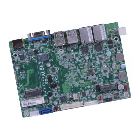
Chapter 2 Chapter 2 - Hardware Installation Board Layout 4-pin Right Angle System Fan 1 DC-in (optional) 4-pin Realtek ALC262 Vertical Type (optional) Intel I211AT or I210IT (opt.) LAN 1 Front Audio (JP11) 9 10 Intel I211AT or USB 2.0 I210IT (opt.) (JP10) LAN 2... -
Page 9: Block Diagram
Chapter 2 Block Diagram DDR3L 1866MHz Channel A PTN3355 SODIMM SATA 3.0 HDMI ASM1442 SATA SATA 3.0 LVDS PTN3460 PCIe x1 (B-key 2242) PCIe x1 GLAN I211AT USB 2.0 GLAN I210IT (opt.) PCIe x1 USB 2.0 (E-key 2230) PCIe x1 GLAN I211AT Intel Atom ®... -
Page 10: System Memory
Chapter 2 Installing the DIMM Module Important: Electrostatic discharge (ESD) can damage your board, processor, disk drives, add-in Note: boards, and other components. Perform installation procedures at an ESD workstation The system board used in the following illustrations may not resemble the actual only. -
Page 11: Jumper Settings
Chapter 2 5. Grasping the module by its edges, align the module into the socket at an approximately 30 Jumper Settings degrees angle. Apply firm even pressure to each end of the module until it slips down into the socket. The contact fingers on the edge of the module will almost completely disappear Clear CMOS Data inside the socket. -
Page 12: Lcd/Inverter Power Select
Chapter 2 LCD/Inverter Power Select Backlight Brightness Select 1-2 On: +3.3V JP11 (default) JP10 1-2 On: +12V 2-3 On: +5V (default) 2-3 On: +5V HDMI HDMI JP11 is used to select the power level of LVDS LCD inverter connector. JP10 is used to select the power level of backlight brightness control: +3.3V or +5V. Important: Before powering-on the system, make sure that the power settings of JP10 match the power specification of backlight control. -
Page 13: Panel Power Select
Chapter 2 M.2 Signal Select Panel Power Select 2 4 6 1 3 5 1-2 On: +12V 2 4 6 1 3 5 3-4 On: +5V JP12 2 4 6 1-2 On: SATA (default) 1 3 5 5-6 On: +3.3V (default) HDMI HDMI... -
Page 14: Rear Panel I/O Ports
Chapter 2 Rear Panel I/O Ports 9~36V DC-in DC-in 12V3 12V4 GND2 GND1 USB 3.0 LAN 1 LAN 2 DC-in C in C in HDMI USB 2.0 The rear panel I/O ports consist of the following: • 1 9~36V DC-in connector •... -
Page 15: Graphics Interfaces
Chapter 2 Graphics Interfaces RJ45 LAN Ports The display ports consist of the following: • 1 VGA port • 1 HDMI port LAN 1 LAN 2 LAN 1 LAN 2 HDMI HDMI HDMI Features • 2 Intel I211AT PCI Express Gigabit Ethernet controllers or 2 optional Intel I210IT PCI ®... -
Page 16: Usb Ports
Chapter 2 USB Ports Driver Installation You may need to install the proper drivers in your operating system to use USB devices. Refer to Chapter 4 for more information. Wake-On-USB Keyboard/Mouse The Wake-On-USB Keyboard/Mouse function allows you to use a USB keyboard or USB mouse to wake up a system from the S3 (STR - Suspend To RAM) state. -
Page 17: I/O Connectors
Chapter 2 Front Audio Connector I/O Connectors Digital I/O Connector Front Audio Mic-L Mic-R Mic-JD Line-R Line-L Line-JD Digital I/O HDMI HDMI The 8-bit Digital I/O connector provides monitoring and control functions to the connected external devices. Front Audio Digital I/O Connector The front audio connector allows you to connect to the line-out and mic-in jacks that are at Function the front panel of your system. -
Page 18: Com (Serial) Ports
Chapter 2 COM (Serial) Port COM 1 RS422 RS232 RS485 Full Duplex DATA- DATA+ COM 1 HDMI COM 1 can be selected among RS232, RS422 and RS485. Configure COM 1 serial communica- tion mode in the BIOS (the “Super IO Configuration” submenu of the Advanced menu). The serial port is an asynchronous communication port with 16C550A-compatible UART that can be used with modems, serial printers, remote display terminals, and other serial devices. -
Page 19: Standby Power Led
Chapter 2 Standby Power LED Front Panel Connector Standby Power LED Front Panel HDMI HDMI HDD LED This LED will light when the hard drive is being accessed. Reset Button This LED will lit red when the system is in the standby mode. It indicates that there is power This switch allows you to reboot without having to power off the system. -
Page 20: Sata (Serial Ata) Connector
Chapter 2 SATA (Serial ATA) Connector SATA (Serial ATA) Power Connector HDMI HDMI SATA SATA 0 Power 6Gb/s SATA 3.0 Features Ground Ground • 1 Serial ATA 3.0 port with data transfer rate up to 6Gb/s • Integrated Advanced Host Controller Interface (AHCI) controller The Serial ATA connector is used to connect the Serial ATA device. -
Page 21: Lvds Lcd Panel Connector
Chapter 2 LVDS LCD Panel Connector LCD/Inverter Power Connector LVDS LCD Panel Connector Function Function Function LCD/Inverter Power Connector LVDS_Out3+ (Odd_3+) LVDS_Out7+ (Even_3+) Dimming Control LVDS_Out3- (Odd_3-) LVDS_Out7- (Even_3-) Panel Power +3.3V LVDS_Out2+ (Odd_2+) LVDS_Out6+ (Even_2+) LCD/Inverter Panel Backlight On/Off Control LVDS_Out2- (Odd_2-) LVDS_Out6- (Even_2-) Power... -
Page 22: Smbus Connector
Chapter 2 SMBus Connector Expansion Slots M.2 (E Key 2230) with PCIe/USB 2.0 signal SMBus HDMI HDMI The SMBus (System Management Bus) connector is used to connect SMBus devices. It is a multiple device bus that allows multiple chips to connect to the same bus and enable each one to act as a master by initiating data transfer. -
Page 23: Battery
Chapter 2 Battery Battery Connector HDMI Connect to the battery connector Battery The lithium ion battery powers the real-time clock and CMOS memory. It is an auxiliary source of power when the main power is shut off. Safety Measures • Danger of explosion if battery incorrectly replaced. •... -
Page 24: Chapter 3 - Bios Setup
Chapter 3 Chapter 3 - BIOS Setup Legends Overview Keys Function The BIOS is a program that takes care of the basic level of communication between the CPU and peripherals. It contains codes for various advanced features found in this system board. Right and Left arrows Moves the highlight left or right to select a menu. -
Page 25: Insyde Bios Setup Utility
Boot Exit Setting incorrect field values may cause the system to malfunction. This is the help for the Project Name AL553 hour, minute, second fi eld. BIOS Version B189.18A Valid range is from 0 to 23, 0 to 59, 0 to 59. IN- Intel(R) Atom(TM) Processor E3950 @ 1.60GHz... - Page 26 Chapter 3 ACPI Configuration Note: If Quiet Boot of Boot menu is set to enabled, BGRT Logo field will appear for This section configures the system ACPI parameters. configuration. Refer to the Boot menu in this chapter for more information. InsydeH2O Setup Utility Rev.
- Page 27 Chapter 3 CPU Configuration Video Configuration This section is used to configure the CPU. This section configures the video settings. InsydeH2O Setup Utility Rev. 5.0 InsydeH2O Setup Utility Rev. 5.0 Advanced Advanced Select which of IGD/PCIe Primary Display <IGD> E n a b l e / D i s a b l e I n t e l Graphics device should be Integrated Graphics Device <Enabled>...
- Page 28 Chapter 3 Audio Configuration SATA Configuration This section is used to configure the audio settings. This section configures the SATA controller. InsydeH2O Setup Utility Rev. 5.0 InsydeH2O Setup Utility Rev. 5.0 Advanced Advanced Enable/Disable HD-Audio Audio Controller <Enabled> Enables or Disables the Support SATA Controller <Enabled>...
- Page 29 Chapter 3 PCI Express Configuration InsydeH2O Setup Utility Rev. 5.0 Advanced This section configures settings relevant to PCI Express root ports. Control the PCI Express PCI Express Root Port 3 (LAN 1) <Enabled> Root Port. Enable: Enable PCIe root InsydeH2O Setup Utility Rev.
- Page 30 Chapter 3 Console Redirection When Console Serial Redirect is set to enabled, the screen will appear like below: This section configures settings relevant to console redirection. InsydeH2O Setup Utility Rev. 5.0 Advanced Enable Console Redirec- InsydeH2O Setup Utility Rev. 5.0 Console Serial Redirect <Enabled>...
- Page 31 Chapter 3 When UseGlobalSetting is set to disabled, the screen will appear like below: COM1 InsydeH2O Setup Utility Rev. 5.0 InsydeH2O Setup Utility Rev. 5.0 Advanced Advanced COM1 COM1 PortEnable <Enabled> PortEnable <Enabled> UseGlobalSetting <Enabled> UseGlobalSetting <Disabled> Terminal Type <VT_100> Baud Rate <115200>...
- Page 32 Chapter 3 SIO FINTEK81803 PC Health Status This section configures the system super I/O chip parameters. This section displays the PC health status. InsydeH2O Setup Utility Rev. 5.0 InsydeH2O Setup Utility Rev. 5.0 Advanced Advanced PC Health Status Confi gure Serial port using COM Port 1 <Enable>...
-
Page 33: Security
Chapter 3 Security Smart Fan Function This section configures the Smart Fan Function. InsydeH2O Setup Utility Rev. 5.0 Main Advanced Security Boot Exit InsydeH20 Setup Utility Rev. 5.0 When Hidden, don’t ex- Current TPM Device <TPM 2.0 (FTPM)> Advanced poses TPM to 0 TPM State All Hierarchies Enabled, Owned TPM Availability... -
Page 34: Boot
Chapter 3 Boot Note: AL553 only supports UEFI boot, no Legacy boot. InsydeH2O Setup Utility Rev. 5.0 Main Advanced Security Boot Exit The number of seconds that the fi rmware will wait Setup Prompt Timeout before booting the original Numlock <On>... -
Page 35: Exit
Chapter 3 Exit Updating the BIOS To update the BIOS, you will need the new BIOS file and a flash utility. Please contact techni- cal support or your sales representative for the files. InsydeH2O Setup Utility Rev. 5.0 Main Advanced Security Boot Exit... -
Page 36: Notice: Bios Spi Rom
Chapter 3 Notice: BIOS SPI ROM 1. The Intel Trusted Execution Engine has already been integrated into this system board. ® Due to the safety concerns, the BIOS (SPI ROM) chip cannot be removed from this system board and used on another system board of the same model. 2. -
Page 37: Chapter 4 - Supported Software
® INF files so that the Intel chipset can be recognized and configured properly in the system. To install the utility, download “AL553 Chipset Driver” zip file at our website. 1. Setup is ready to install the utility. Click “Next”. - Page 38 Intel Graphics Drivers 3. Go through the readme document for system re- quirements and installation To install the driver, download “AL553 Graphics Driver” zip file at our website. tips then click “Next”. 1. Setup is now ready to install the graphics driver.
- Page 39 Chapter 4 Audio Drivers Intel LAN Drivers To install the driver, download “AL553 Audio Driver” zip file at our website. To install the driver, download “AL553 LAN Driver” zip file at our website. 1. Setup is ready to install the 1.
- Page 40 Chapter 4 Intel Trusted Execution Engine Driver 4. Click “Install” to begin the installation. To install the driver, download “AL553 TXE Driver” zip file at our website. 1. Tick “I accept the terms in the License Agreement“ and then click “Next.”...
- Page 41 SIO Driver 3. The step displays the installing status in the progress. To install the driver, download “AL553 SIO Driver” zip file at our website. 1. Setup is ready to install the driver. Click “Next”. 4. Click “Finish“ when the installation is complete.
- Page 42 Chapter 4 5. Setup is now installing the 3. Go through the readme docu- driver. ment for system requirements and installation tips then click “Next”. 4. Setup is ready to install the driver. 6. Click “Yes, I want to restart Click “Next”.
-
Page 43: Appendix A - Troubleshooting Checklist
Appendix A Appendix A - Troubleshooting Checklist The picture seems to be constantly moving. Troubleshooting Checklist 1. The monitor has lost its vertical sync. Adjust the monitor’s vertical sync. 2. Move away any objects, such as another monitor or fan, that may be creating a magnetic This chapter of the manual is designed to help you with problems that you may encounter field around the display. - Page 44 Appendix A Hard Drive System Board 1. Make sure the add-in card is seated securely in the expansion slot. If the add-in card is Hard disk failure. loose, power off the system, re-install the card and power up the system. 1.
Need help?
Do you have a question about the AL553 and is the answer not in the manual?
Questions and answers