Advertisement
Quick Links
Advertisement

Related Manuals for DFI ADN553


Summary of Contents for DFI ADN553
- Page 1 ADN553 Embedded 3.5" SBC User’s Manual © July 17, 2023 DFI Inc.
- Page 2 1. The changes or modifications not expressly approved by the party responsible for com- are the properties of the respective owners. pliance could void the user’s authority to operate the equipment. 2. Shielded interface cables must be used in order to comply with the emission limits. User's Manual | ADN553...
- Page 3 ► Smart Fan Function ............30 Serial Port Console Redirection ..................30 Serial Port Console Redirection ► Console Redirection Settings ......31 Network Stack Configuration..................31 USB Power Control ......................32 Chipset ..........................33 System Agent (SA) Configuration ................33 PCH-IO Configuration ....................34 User's Manual | ADN553...
- Page 4 It must be returned to the purchase point, factory or authorized service agency for all such work. 4. We will not be liable for any indirect, special, incidental or consequential damages to the product that has been modified or altered. User's Manual | ADN553...
- Page 5 Make sure the system is placed or mounted correctly and stably to prevent the chance of dropping or falling may cause damage. • The openings on the system shall not be blocked and shall be kept in distance from User's Manual | ADN553...
- Page 6 LAN3 option with M.2 3052 PCIe x1. REAR I/O Ethernet 3 x 2.5GbE (RJ-45) 4 x USB 3.2 Gen2 2 x USB 2.0 1 x HDMI Display 1 x Type-C DP Alt. Mode 1 x LVDS/eDP User's Manual | ADN553...
- Page 7 3.5" SBC Form Factor PCB: 1.6mm MECHANISM Height Top Side: 15mm Bottom Side: 4mm Temperature Operating: -5 to 65°C Humidity Operating: 5 to 90% RH ENVIRONMENT MTBF STANDARDS AND CE, FCC Class B, RoHS Certifications CERTIFICATIONS User's Manual | ADN553...
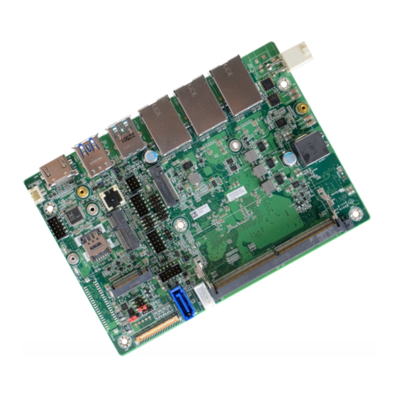
- Page 8 Chapter 1 INTRODUCTION X Dimensions X Block Diagram User's Manual | ADN553...
- Page 9 SC8005 R692 FB8000 SOU1 R8026 Q8006 DPQ1 Q8003 Q8019 Q8004 C8005 U8012 TSQ1 Q8002 UBD6 UBD3 UBD4 UBD1 UBD2 UBD5 D8001 AUC19 D8002 AUC20 D8000 ADN553 REV.2 MADE IN TAIWAN © July 06, 2023 DFI Inc. User's Manual | ADN553...
- Page 10 UBU1 UBU1 UBC3 UBC3 CN11 CN11 AUD2 DDI_B AUD2 DDI_B UBEC1 UBEC1 M2CN3-G4 HDMI M2CN3-G4 HDMI SW1000 SW1000 „ 1-2 On: 12V (default) „ 2-3 On: 5V „ 1-2 On: 3.3V (default) „ 2-3 On: 5V User's Manual | ADN553...
- Page 11 C8009 C8008 LC8006 M2CN2-G5 U8007 M2CN4 COM1 U8000 M2CN3-G3 AUU1 TSJ1 U8011 C8007 C8006 UBU1 UBC3 CN11 AUD2 DDI_B UBEC1 M2CN3-G4 HDMI SW1000 „ 1-2 On: 12V „ 3-4 On: 5V „ 5-6 On: 3.3V (default) User's Manual | ADN553...
- Page 12 TSJ1 U8011 C8007 C8006 Q8002 UBD6 UBD4 UBD1 UBD2 UBU1 UBD5 UBD3 D8001 UBC3 AUC19 D8002 AUC20 CN11 AUD2 DDI_B UBEC1 M2CN3-G4 HDMI D8000 ADN553 SW1000 REV.2 MADE IN TAIWAN Assignment Assignment TACH VOUT DC_IN DC_IN User's Manual | ADN553...
- Page 13 U8011 U8011 C8007 C8007 C8006 C8006 UBU1 UBU1 UBC3 UBC3 CN11 CN11 AUD2 DDI_B AUD2 DDI_B UBEC1 UBEC1 M2CN3-G4 HDMI M2CN3-G4 HDMI SW1000 SW1000 Assignment Assignment PWM Brightness Control Panel Power +3.3V Backlight On/Off Inverter Power User's Manual | ADN553...
- Page 14 AUD2 DDI_B UBEC1 M2CN3-G4 HDMI M2CN3-G4 HDMI SW1000 SW1000 Assignment Assignment RS232 RS422 RS485 Power Button SUS LED Power DCD- TXD- Data- SUS LED TXD+ Data+ Reset HDD LED SOUT RXD+ DTR- RXD- DSR- RTS- CTS- User's Manual | ADN553...
- Page 15 UBC3 UBC3 UBU1 CN11 AUD2 DDI_B CN11 AUD2 DDI_B UBEC1 UBEC1 M2CN3-G4 HDMI M2CN3-G4 HDMI SW1000 SW1000 Assignment Assignment Assignment Assignment Mic-L DIO7 DIO6 DIO5 DIO4 Mic-R DIO3 DIO2 Line-Out-R Mic-JD DIO1 DIO0 5VSB Line-Out-L Line-JD User's Manual | ADN553...
- Page 16 UBC3 UBU1 CN11 AUD2 DDI_B CN11 AUD2 DDI_B UBEC1 UBEC1 M2CN3-G4 HDMI M2CN3-G4 HDMI SW1000 SW1000 Assignment Assignment Assignment Assignment 3V3SB ESPI_CLK ESPI_RST# -DATA -DATA ESPI_ALT# UART_TX +DATA +DATA ESPI_D0 ESPI_D1 ESPI_CS ESPI_D2 UART_RX ESPI_D3 3V3SB User's Manual | ADN553...
- Page 17 COM1 U8000 M2CN3-G3 AUU1 TSJ1 U8011 C8007 C8006 UBU1 UBC3 CN11 AUD2 DDI_B UBEC1 LVDSA_Out0+ LVDSB_Out0+ M2CN3-G4 HDMI LVDSA_Out0- LVDSB_Out0- SW1000 LVDSA_CLK1+ LVDSB_CLK1+ LVDSA_CLK1- LVDSB_CLK1- LVDS_DDC_CLK LVDS_DDC_DATA +3.3V Panel Power Panel Power Panel Power Panel Power User's Manual | ADN553...
- Page 18 U8008 M2CN2 C8009 eDP_GND eDPB_LANE1_C_P C8008 M2CN2-G5 LC8006 U8007 M2CN4 COM1 U8000 M2CN3-G3 AUU1 TSJ1 eDP_GND eDPB_LANE1_C_N U8011 C8007 C8006 UBU1 UBC3 CN11 eDP_GND AUD2 DDI_B UBEC1 M2CN3-G4 HDMI eDP_HPD_CON_1 eDPB_LANE2_C_P SW1000 eDPB_LANE2_C_N eDPB_LANE3_C_P eDPB_LANE3_C_N EDP_VCC_PANEL User's Manual | ADN553...
- Page 19 4. Make sure the notch on card is aligned to the key on the socket. 5. Make sure the standoff screw is removed from the standoff. M.2 Module M.2 Socket Stand-off Notch M.2 B-Key M.2 E-Key M.2 M-Key User's Manual | ADN553...
- Page 20 Screw tight the card onto the stand-off with a screw driver and a stand-off screw until the gap between the card and the stand-off closes up. The card should be lying parallel to the board when it’s correctly mounted. User's Manual | ADN553...
- Page 21 3. Locate the SO-DIMM socket on the system board 4. Make sure the notch on memory card is aligned to the key on the socket. M.2 B-Key Retention Notch Notch DDR5 SO-DIMM Retention Clip Socket Top View DDR5 SO-DIMM 4 5 ° User's Manual | ADN553 Step 1...
- Page 22 Inspect that the clip sits in the notch. If not, please pull the clips outward, release and remove the card, and mount it again. User's Manual | ADN553...
- Page 23 Do not use excessive force or place direct pressure on the board. It affects the It is typical that the chassis is customized, in which case the installation shall vary board's performance and may damage the motherboard. according to the design of the chassis instead of the instructions provided here. User's Manual | ADN553...
- Page 24 When “X” appears on the left of a particular field, it indicates that a submenu which contains additional options are available for that field. To display the submenu, move the highlight to that field and press <Enter>. User's Manual | ADN553...
- Page 25 The time format is <hour>, <minute>, <second>. The time is based on the 24-hour military-time clock. For example, 1 p.m. is 13:00:00. Hour displays hours from 00 to 23. Minute displays min- utes from 00 to 59. Second displays seconds from 00 to 59. User's Manual | ADN553...
- Page 26 (G3 state). • S0 State The system automatically powers on after power failure. • S5 State The system enter soft-off state after power failure. Power-on signal input is required to power up the system. User's Manual | ADN553...
- Page 27 Enable or disable turbo mode of the processor. This field will only be displayed when EIST is Enable/Disable Me FW Image Re-Flash function. enabled. C states Enable or disable CPU Power Management. It allows CPU to enter "C states" when it’s idle and nothing is executing. User's Manual | ADN553...
- Page 28 To clear the existing TPM encryption, select "TPM Clear" and restart the system. This field is Set SuperIO WatchDog Timer Timeout value. The range is from 0 (disabled) to 255. not available when "Security Device Support" is disabled. Note: The sub-menus are detailed in following sections. User's Manual | ADN553...
- Page 29 ► Serial Port 1 Configuration Hardware Monitor This section displays the system’s health information, i.e. voltage readings, CPU and system temperatures, and fan speed readings Serial Port Enable or disable serial port. Smart Fan Function Smart Fan Function Setting. User's Manual | ADN553...
- Page 30 SYS_FAN Mode : [Manual Mode, SMART FAN IV ] Fan control mode select. Temperature 1, 2, 3, 4 The value of temperature. FD/RPM 1, 2, 3, 4 The value of Fan Duty/RPM when temperature is T1, T2, T3, T4. User's Manual | ADN553...
- Page 31 Select stop bits: 1 bit or 2 bits. Media detect count Set the number of times the presence of media will be checked. Use either +/- or numeric keys to set the value. User's Manual | ADN553...
- Page 32 Chapter 3 BIOS SETTINGS Advanced USB Power Control Server CA Configuration 5_Dual: Support system wake up from S3/S4 by USB KB&MS 5V: No support system wake up from S3/54 by USB KB&MS User's Manual | ADN553...
- Page 33 Chapter 3 BIOS SETTINGS X Chipset Chipset System Agent (SA) Configuration Please select a submenu and press Enter. The submenus are detailed in the following pages. User's Manual | ADN553...
- Page 34 Select one of the PCI Express channels and press enter to configure the following settings. PCI Express Configuration Settings LAN 1,2,3 M.2-B, M.2-E, M.2-M SATA Configuration Control the PCI Express Root Port. SATA Device Otpions Settings HD Audio Configuration HD Audio Subsystem Configuration Settings User's Manual | ADN553...
- Page 35 The mode selection determines how the SATA controller(s) operates. • Enabled HDA will be unconditionally enabled. • AHCI This option allows the Serial ATA controller(s) to use AHCI (Advanced Host Controller Interface). Ports Enable or disable the Serial ATA port. User's Manual | ADN553...
- Page 36 Clear the database from the NVRAM, including all the keys and signatures installed in the Key Management menu. Press Enter and a prompt will show up for you to confirm. Key Management Enables expert users to modify Secure Boot Policy variables without full authentication. User's Manual | ADN553...
- Page 37 If “Quiet Boot” is enabled, “BGRT Logo” will show up for configuration. • Restore Setting from file This field will appear only when a USB flash device is detected. Select this field to restore set-ting from the USB flash device. User's Manual | ADN553...
- Page 38 When the BIOS IC needs to be replaced, you have to populate it properly onto the system board after the EEPROM programmer has been burned and follow the technical person's instructions to confirm that the MAC address should be burned or not. User's Manual | ADN553...
- Page 39 12V(Default)/5V, 1.5A USB2.0 PINREX, 52C-90-10GBE0: 2*5, 2.0mm, BOX HEADER 5V/1A eDP Panel Power: 3.3V(Default)/5V/12V, 1.5A DPCN2 STM, MSAK24025P40C: 1*40P, 0.5mm, eDP CONN eDP Inverter Power: 12V(Default)/5V, 1.5A SATA Power J1001 MOLEX, 53398-0571: 5P, 1.25mm, Wafer 5V/12V, 1.5A User's Manual | ADN553...
Need help?
Do you have a question about the ADN553 and is the answer not in the manual?
Questions and answers