Table of Contents
Advertisement
Advertisement
Table of Contents

Subscribe to Our Youtube Channel
Related Manuals for Hyundai J300 series


Summary of Contents for Hyundai J300 series
-
Page 2: Hazardous High Voltage
J300 INSTRUCTION MANUAL SAFETY For the Best Results with J300 Series inverter, read this manual and all of the warning sign attached to the inverter carefully before installing and operating it, and follow the instructions exactly. Keep this manual handy for your quick reference. - Page 3 WARNING : The user is responsible for ensuring that all driven machinery, drive train mechanism not supplied by Hyundai, Ltd., and process line material are capable of safe operation at an applied frequency of 150% of the maximum selected frequency range to the AC motor. Failure to do so can result in destruction of equipment and injury to personnel should a single point failure occur.
- Page 4 J300 INSTRUCTION MANUAL WARNING : This equipment has high leakage current and must be perminatly hard wired to earth via two indipendent cable. MOTORS a) Class I motor must be connected to protective earth via low resistive path (<0.1 ) b) Any motor used must be of suitable rating.
- Page 5 J300 INSTRUCTION MANUAL Revision History Table Operation Manual Revision Contents The Date of lssue Number...
-
Page 6: Table Of Contents
J300 INSTRUCTION MANUAL TABLE OF CONTENTS Page 1. SAFETY PRECAUTIONS 2. INSPECTION UPON UNPACKING 3. APPEARANCE AND NAMES OF PARTS 4. INSTALLATION 5. WIRING 6. OPERATION 7. OPERATION OF THE DIGITAL OPERATOR 8. PROTECTION FUNCTION 9. TROUBLESHOOTING 10. MAINTENANCE AND INSPECTION 10-1 11. -
Page 7: Safety Precautions
J300 INSTRUCTION MANUAL 1. SAFETY PRECAUTIONS 1. Installation CAUTION P.4-1 Be sure to install the unit on flame resistant material such as metal Otherwise, there is a danger of fire. Be sure not to place anything inflammable in the vicinity. P.4-1 Otherwise, there is a danger of fire. - Page 8 J300 INSTRUCTION MANUAL CAUTION P.5-2 Make sure that the input voltage is : Three phase 200 to 220V/50Hz, 200 to 230V/60Hz Three phase 380 to 415V/50Hz, 400 to 460V/60Hz P.5-2 Be sure not to input a single phase to a 3 phase type. Otherwise, there is a danger of fire.
- Page 9 J300 INSTRUCTION MANUAL CAUTION Input phase failure protection (1) J300-5 version inverter are provided with the phase failure protection on the power supply. (2) When a buzzer, lamp, noise filter or transformer is connected between the input power terminals (L1, L2, L3) and input power fuses, input phase failure cannot be protected. (L1) (L2) (L3)
- Page 10 J300 INSTRUCTION MANUAL 3. Control and operation WARNING Be sure to turn on the input power supply after mounting the surface cover. P.6-1 While being energized, be sure not to remove the cover. Otherwise, there is a danger of electric shock. Be sure not to operate the switches with wet hands.
- Page 11 J300 INSTRUCTION MANUAL CAUTION Radiating fin and discharging resistor will have high temperature. P.6-2 Be sure not to touch them. Otherwise, there is a danger of getting burned. Low to high speed operation of the inverter can be easily set. Be sure to P.6-2 operate it after checking the tolerance of the motor and machine.
- Page 12 J300 INSTRUCTION MANUAL 5. Others WARNING Never modify the unit. Otherwise, there is a danger of electric shock and/or injury. CAUTION Withstand voltage tests and insulation resistance tests (megger tests) are executed before the units are shipped, so that there is no need to conduct these tests before operation. When conducting megger tests as a part of daily inspection, be sure that these tests are only executed between the main circuit and the ground.
- Page 13 J300 INSTRUCTION MANUAL CAUTION Do not insert leading power factor capacitors or surge absorbers between the output terminals of the inverter and the motor. Surge absorber Earth leakage breaker (T1) (T2) (T3) (L1)(L2)(L3) R, S, T Power supply Leading power factor capacitor Be sure to ground the grounding terminal, When inspecting the unit, after turning the power supply off be sure to wait unitl the CHARGE lamp beside the control terminal is off before opening the cover.
- Page 14 J300 INSTRUCTION MANUAL CAUTION EMI filter Inverter Noise (T1) Power R(L1) source Power (T2) Motor S(L2) Motor source (T3) T(L3) Inverter EMI filter Terminal grounding Ground the frame. Piping (to be grounded) or shielded wire Noise Completely ground the shield made of metal screen, enclosed panel, etc.
-
Page 15: Inspection Upon Unpacking
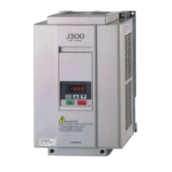
Make sure that the product is the one you ordered by checking the specifications label on the front of the cover. Model abbreviation (The example is for the J300-055HFE4) 055LF5 inverter HYUNDAI J300 Input Voltage Output Voltage Input frequency Maximum applicable motor(4P, kw) -
Page 16: Appearance And Names Of Parts
J300 INSTRUCTION MANUAL 3. APPEARANCE AND NAMES OF PARTS 3.1 Names of Parts Blind cover Front cover A set screw Charge lamp(LED) Digital operator Control circuit terminals Main circuit terminals Wiring holes Cover Case Earth terminal... - Page 17 J300 INSTRUCTION MANUAL 4. INSTALLATION CAUTION Be sure to install the unit on flame resistant material such as metal. Otherwise, there is a danger of fire. Be sure not to place anything inflammable in the vicinity. Otherwise, there is a danger of fire. Be sure not to let the foreign matter enter such as cut wire refuse, spatter from welding, iron refuse, wire, dust, etc.
- Page 18 J300 INSTRUCTION MANUAL For cooling purposes, be sure that the inverter is installed vertically. In addition, be sure that it is separated from other components and walls. If foreign matter is introduced into the interior of the inverter, this may cause malfunctions, so make sure that no foreign matter can enter it. Flow of air 10cm or more Wall...
- Page 19 J300 INSTRUCTION MANUAL Precaution for installation and wiring When executing the wiring work or another work, attach a cover on the vent hole (slit) on the top of the inverter to prevent wire chips, weld spatters, iron scraps, or dust from falling into the inverter.
- Page 20 J300 INSTRUCTION MANUAL 5. WIRING WARNING Be sure to ground the unit. Otherwise, there is a danger of electric shock and/or fire. Wiring work shall be carried out by electrical experts. Otherwise, there is a danger of electric shock and/or fire. Implement wiring after checking that the power supply is off.
- Page 21 J300 INSTRUCTION MANUAL CAUTION Make sure that the input voltage is : Three phase 200 to 220V/50Hz, 200 to 230V/60Hz Three phase 380 to 415V/50Hz, 400 to 460V/60Hz Be sure not to input a single phase to a 3 phase type. Otherwise, there is a danger of fire.
- Page 22 J300 INSTRUCTION MANUAL The terminal board will be exposed when the front cover or terminal cover ( 220HF to 2200HF) is removed. Wire the inverter in this state. 5.1 Wiring the Power Supply and Motor (RB) (L1) (L2) (L3) (+1) (T1) (T2) (T3)
- Page 23 J300 INSTRUCTION MANUAL Note 3 : Be sure that the specified grounding is carried out. Be sure to separate the unit's grounding pole from those of other heavy electric machinery, and avoid using common grounding poles. If multiple inverters are used, make sure that the grounding connections do not create a loop. Improper grounding Proper grounding Inverter...
- Page 24 J300 INSTRUCTION MANUAL 5.2 Wiring of Control Circuit Terminals SOURCE TYPE wiring (Factory settings for European version) Failure alarm Input intelligent terminal Frequency setting (500 to 2 Current input For output Frequency meter DC 4 to 20mA Intelligent terminal 27 VDC 50mA 50mA max.
- Page 25 J300 INSTRUCTION MANUAL Insulate No grounding necessary Connect FG (frame ground) of the inverter. NOTE 3 : When the frequency setting signal is turned on and off with a contact, use a relay which will not cause contact malfunctions, even with the extremely weak currents and voltages, such as crossbar twin contacts, etc.
- Page 26 Note : Make sure of the short-circuit bar or wire between the Note : Make sure of the short-circuit bar or wire between the terminals PLC and P24. terminals CM1 and PLC. J300 series J300 series DC24V DC24V YTR48 type output module...
- Page 27 J300 INSTRUCTION MANUAL 5.4 Wiring Equipment, Options (EMI filter, etc.) Standard equipment (200V Class) Wiring Applicabie equipment Power supply Motor Power lines Signal lines Inverter Power output Extemol FM1, CM1, Signal lines Electrom- model lines Earth leakage (kw) resistor PCL, FW, 8, 7, P24, AL0, agnetic R, S, T, U, V...
- Page 28 J300 INSTRUCTION MANUAL The applicable equipment is for a Hyundai standard four pole squirrel-cage motor. NOTE 1 : Be sure to consider the capacity of the circuit breaker to be used. NOTE 2 : NOTE 3 : Be sure to use bigger wires for power lined if the distance exceeds 20m.
- Page 29 J300 INSTRUCTION MANUAL 5.4 Terminal Width (1) Main circuit terminal Width Screw Terminal layout Type (mm) diameter Insternal short circuit bar 055, 075LF, HF (RB) (L1) (L2) (L3) (+1) (T1) (T2) (T3) (PE) Insternal short circuit bar 110, 150LF, HF (L1) (L2) (L3) (+1) (T1) (T2) (T3) (PE)
-
Page 30: Control Circuit
J300 INSTRUCTION MANUAL Control circuit Terminal Standard setting of Terminal description and function Remarks symbol intelligent terminal Frequency monitor Common for monitor Dry contact Common terminal for the external Close : ON (run) power source of the sequencer(PLC) Open : OFF (stop) Internal power source for the frequency monitor and intelligent input terminal Min. -
Page 31: Control Circuit Terminals
J300 INSTRUCTION MANUAL 5.6 Control circuit Terminals Terminal symbol Description Terminal name Analog : Output frequency, current, torque Digital : Output frequency x frequency converted value Monitor terminal (Set in the remote operator monitor mode), max. pulse : 3.6kHz Common terminal 1 Common terminal for the monitor terminal Common terminal for the external power source of the sequencer Internal interface common... - Page 32 J300 INSTRUCTION MANUAL Terminal symbol Description Terminal name Initialization of a voltage signal by an external command is between Frequency command 0 and 10VDC. (Switching from 0 to 5V is executed by A48). power terminal When inputting 4-20mA, turn the input terminal at ON. H O OI L H O OI L H O OI L...
-
Page 33: Terminal Connection Diagram
J300 INSTRUCTION MANUAL 5.7 Terminal Connection Diagram Power supply Inverter MccB (T1)U R(L1) Three phase Motor (T2)V power supply S(L2) (T3)W T(L3) * : Be sure to remove the internal short circuit bar when using DC (+1)PD reactor. (+)P 24 VDC Regenerative resistor 055, 075HF : RB2, two each in series. - Page 34 J300 INSTRUCTION MANUAL 6. OPERATION 6.1 Before Starting Operation Prior to the test run, check the following WARNING Be sure to turn on the input power supply after mounting the surface cover. While being energized, be sure not to remove the cover. Otherwise, there is a danger of electric shock.
- Page 35 J300 INSTRUCTION MANUAL CAUTION Radiating fin and discharging resistor will have high temperature. Be sure not to touch them. Otherwise, there is a danger of getting burned. Low to high speed operation of the inverter can be easily set. Be sure to operate it after checking the tolerance of the motor and machine.
-
Page 36: Test Run
J300 INSTRUCTION MANUAL 6.2 Test Run CAUTION Check the following before and during the test run. Otherwise, there is a danger of machine breakage. Was the short-cut bar between+1 and + connected? (This check applies only when the DCL is not used.) Was the direction of the motor correct? Was the inverter tripped during acceleration of deceleration? -
Page 37: Displayed
J300 INSTRUCTION MANUAL Operating with digital operator: Running from external command: Procedure (1) Turn on ELB to supply power to the inverter. Make sure that the POWER LED on the digital operator turns ON. (2) Press the key once to display (3) Press of the digital operator four times to display (4) Press the... - Page 38 J300 INSTRUCTION MANUAL The failure alarm signal is generated from the terminal AL0 and AL1 when a failure happens. At this time the contents of the failure are displayed on the digital operator. Whether the alarm terminal output is to be turned on or off during normal run can be selected by the extension function The alarm output terminals at initial setting are as follows(2).
- Page 39 J300 INSTRUCTION MANUAL Resetting (Any one of A, B and C is possible) A) Turn control terminal 1 on. (In the initialization at factory before shipment, intelligent input terminal 1 is allocated to the reset RS terminal.) When the internal interface power source B) Press on the digital operator.
-
Page 40: Operation Of The Digital Operator
J300 INSTRUCTION MANUAL 7. OPERATION OF THE DIGITAL OPERATOR The standard type digital operator is modified so as to be used easily by minimizing key operations. Data can be set simply. 7.1 Names of Parts POWER Lamp Monitor (LED display) Power lamp of control circuit This display shows frequency, motor current, motor revolution speed, and... -
Page 41: Key Description
J300 INSTRUCTION MANUAL 7.3 Key Description The key are used to select the code and change the data. When Data display key is pressed once, the monitor mode is displayed Code display first and then are one by one. If the UP/DOWN key key is pressed once again when is displayed, the display... - Page 42 J300 INSTRUCTION MANUAL 7.4 Explanation of Screen Display When the inverter is turned on, the latest display appears. However, when the display unit for data of the commands F2 to F14 is turned off, the commands (F2 to F14) are displayed. (d10 and d11 excluded) Data during running in any function mode or extension function mode can be displayed.
- Page 43 J300 INSTRUCTION MANUAL 7.5 Transition of Each Code To extension function code setting <Monitor mode> <Extension function mode> Output frequency monitor Reduced voltage soft start Control method setting setting Motor revolution Motor capacity setting Running mode selection speed monitor Motor poles setting Jogging frequency setting Output current monitor...
-
Page 44: Refer To
J300 INSTRUCTION MANUAL 7.6 Digital Operator Initialization List (1) Monitor mode, function mode The standard set value of each code number is displayed. The extension functions shown on page 7-6 can be set by the extension function setting function. Screen display Settable Display Initial... - Page 45 J300 INSTRUCTION MANUAL (2) Extension function mode Each function name and settable range to the extension function mode are shown below. Set the extension code to be changed by Screen display Settable Display Settable Externsion function name for 2nd Remarks Code order value...
- Page 46 J300 INSTRUCTION MANUAL 7.7 Explanation of Modes (1) Monitor mode contents Monitor Contents and display mode contents The frequency outputted by the inverter is monitored. The display is as shown below. 0. 00 Display when stopped Output A frequency between 0.01Hz and 0.
- Page 47 J300 INSTRUCTION MANUAL Monitor Contents and display mode contents The product of the value of frequency converted value setting (A47) and that of output frequency (d0) is displayed on the monitor. 9. 9 9 0.0 to 9.99 Frequency converted 1 0.0 9 9.9 10.00 to 99.99 value...
- Page 48 J300 INSTRUCTION MANUAL (2) Function mode Monitor Contents and display mode contents Methods for setting the output frequency are as follows : 1. Digital operator -------------------------- Refer to this setting. 2. Control circuit terminal ----------------- Refer to this setting. (multistage speed command) 3.
- Page 49 J300 INSTRUCTION MANUAL Monitor Contents and display mode contents Set the motor direction. Set the motor direction when running by pressing the key. NOTE : The setting during run is impossible. Running direction Initial set value Forward run Switching can be done by pressing key.
- Page 50 J300 INSTRUCTION MANUAL Monitor Contents and display mode contents These commands set and display Acc. time ( ) and Dec. time ( 9 9 9 Accelera- Setting range Period tion time 1 Initial value 3 0.0 Every 0.01s 0.01 to 9.99s and 2 Every 0.1s 10.0 to 99.9s...
-
Page 51: Operation
J300 INSTRUCTION MANUAL Monitor Contents and display mode contents Switching the run command and frequency command setting modes Set the run command and frequency command sending destinations. The standard specification selection range is from 00 to 03. Frequency command to Set value Run command to Initial value... -
Page 52: Wiring
J300 INSTRUCTION MANUAL Monitor Contents and display mode contents Adjust the analog meter connected to the frequency monitor (Source type wiring terminal. (Initial setting of the [FM] terminal: Analog frequency monitor) Refer page 5-3) When operation starts, t/T output between FM and CM1 terminals is proportional to the output data. - Page 53 J300 INSTRUCTION MANUAL Returning to the initialization (State set at factory before shipment) When returning the equipment to the initial state set at factory before shipment for some reason, follow the following procedure. (1) Allocate STN (set value ) to one of the input intelligent terminals. (Use in the extension function mode to set the intelligent terminals.) (However,...
- Page 54 J300 INSTRUCTION MANUAL (3) Extension function mode contents Monitor Contents and display mode contents Set the control method. Select one of the following control codes. Initial set value V/f control (VC) Control Constant torque characteristics method setting V/f control (VP1) Reduced torque characteristics, 1.5 power V/f control (VP2)
- Page 55 J300 INSTRUCTION MANUAL Monitor Contents and display mode contents Set the response speed (ASR system gain) between the inverter and motor. When increasing or decreasing the current motor response speed, adjust the ASR system gain. When the set value is decreased, the response speed is increased. When the set value is increased, the response speed is decreased.
- Page 56 J300 INSTRUCTION MANUAL Monitor Contents and display mode contents Set the limits of frequency setting within the start frequency adjustment range and maximum frequency setting range. When a value beyond the limits is inputted from the operator, it will not be stored. Even if a value beyond the limits is inputted as external analog input, the set value will not be changed.
- Page 57 J300 INSTRUCTION MANUAL Monitor Contents and display mode contents Set the switching frequency of the power module. NOTE1: The initial value of carrier frequency varies with the inverter capacity (NOTE 1) Carrier Carrier frequency initial value Initial value frequency Applicable Inverter(kw) Carrier frequency(kHz) setting 1.5 15...
-
Page 58: Initial Set Value 1 2
J300 INSTRUCTION MANUAL Monitor Contents and display mode contents Set the electronic thermal level. Set the thermal level in accordance with the rated current of the motor in units of 1 (%). Motor rated current Adjustment level = Electronic Inverter rated current thermal Time(s) level... - Page 59 J300 INSTRUCTION MANUAL Monitor Contents and display mode contents Set the frequency for starting output for an external frequency command (0 to 10V, 0 to 5V, 4 to 20mA) and the frequency for ending output. When 0 Hz is set, this function will be canceled. Initial value External frequency setting start...
- Page 60 J300 INSTRUCTION MANUAL Monitor Contents and display mode contents Set the usage ratio(%) for 100 seconds of BRD NOTE 1 : The internal BRD circuit is not mounted in an When the BRD operation exceeds this setting inverter other than the types 055HF, 055LF, 075HF and 075LF the operation will be stooped.
- Page 61 J300 INSTRUCTION MANUAL Monitor Contents and display mode contents Select the output monitors signal at the control circuit terminal FM from the table indicated below. Set value Function Monitor Setting method Analog output frequency monitor Initial value signal Analog current monitor selection Analog torque monitor (Note) Initial value...
- Page 62 J300 INSTRUCTION MANUAL Monitor Contents and display mode contents When selecting the frequency arrival signal at the output terminal, select the arrival signal output method. Frequency arrival Setting method signal output method Initial value Set value Function At the time of constant speed arrival Optionally set frequency or more Only optionally set frequency Set optional frequencies of set value 1 and set...
- Page 63 J300 INSTRUCTION MANUAL Monitor Contents and display mode contents Adjust reduced voltage start. NOTE : How to set Initial value : There is no reduced voltage. The rush current Reduced at the start of the inverter is increased but the voltage motor reaction time is decreased.
- Page 64 J300 INSTRUCTION MANUAL Monitor Contents and display mode contents Set the base frequency and maximum frequency. Setting method Setting example Base frequency 100% 100% setting Initial value Maximum frequency 60§Ô 120Hz f 60§Ô f setting (A62) base frequency (A62) base frequency:60Hz and (A63) maximum (A63) maximum frequency : (400)
- Page 65 J300 INSTRUCTION MANUAL Monitor Contents and display mode contents Possible to select a performance of a release timing of alarm signal when giving reset signal from [RS] terminal Set value Performance Selection Reset signal from [RS] terminal Alarm reset Initial value output terminal perfor-...
- Page 66 J300 INSTRUCTION MANUAL Monitor Contents and display mode contents This function is used to select a method to enter the target value for executing each PID function Set value Performance Setting method Target The target value depends on the value level set value.
- Page 67 J300 INSTRUCTION MANUAL Monitor Contents and display mode contents Unusable Ro-T- option selection...
- Page 68 J300 INSTRUCTION MANUAL Monitor Contents and display mode contents A terminal function is allocated to each of the input intelligent terminals 1 to 8. When using a function other than the standard set functions or changing the terminal order, set the function for each terminal.
- Page 69 J300 INSTRUCTION MANUAL Monitor Contents and display mode contents A terminal function is allocated to each of the output intelligent terminals 11 and 12. When using a function other than the standard set functions or changing the terminal order, set the function for each terminal.
- Page 70 J300 INSTRUCTION MANUAL Monitor Contents and display mode contents The input intelligent terminals 4 to 1 can be changed individually to the a contact or b contact specification. Select the set value by pressing the keys by combining the contacts a and b with reference to the table indicated below.
-
Page 71: Protection Function
INSTRUCTION MANUAL 8. PROTECTION FUNCTIONS The J300 series inverters are equipped with protection functions against overcurrent, overcoltage, and undervoltage which protect the inverter. If the protection functions are engaged, the output is shut down, motor runs free and holds that condition until it is reset. - Page 72 J300 INSTRUCTION MANUAL Description Display Contents Option 1 Optional An error occurs in the optional connection (connector, etc.) connection Option 2 error Option 1 Optional An error message outputted from the optional PCB NOT 5 PCB error Option 2 Constant speed The detector which is built in the power module operates.
-
Page 73: Troubleshooting
J300 INSTRUCTION MANUAL HHIS-WZ-PE-002(02) 9. TROUBLESHOOTING 9.1 Error Messages and Diagnosis When the inverter goes wrong, it operates as indicated below. Find the cause and take contermeasures. Error Messages and Diagnosis Symptom Display on the Cause LCD of the digital operator Check Countermeasure (explanation... - Page 74 J300 INSTRUCTION MANUAL HHIS-WZ-PE-002(02)
- Page 75 J300 INSTRUCTION MANUAL HHIS-WZ-PE-002(02) Symptom Display on the Cause LCD of the digital operator Countermeasure Check (explanation (display on the of message) LCD of the remote operator) Check the wiring between E 1 4 the inverter and motor Ground fault on the Correct the portions and also check the motor output side of the...
-
Page 76: Installation
J300 INSTRUCTION MANUAL HHIS-WZ-PE-002(02) Symptom Display on the Cause LCD of the digital operator Countermeasure Check (explanation (display on the of message) LCD of the remote operator) Check whether the speed Set a longer acceleration (NOTE 1) Failure detected E 3 3 was increased rapidly. - Page 77 J300 INSTRUCTION MANUAL Symptom Display on the Cause LCD of the digital operator Countermeasure Check (explanation (display on the of message) LCD of the remote operator) Check for an overload Lower the load ratio. Check whether the Set the thermal relay to thermal relay is set to an an appropriate value.
- Page 78 J300 INSTRUCTION MANUAL Symptom Probable cause Countermeasure Is power being supplied to terminals Check terminals R(L1), S(L2), T(L3), The inverter R(L1), S(L2), and T(L3)? U(T1), V(T2), and W(T3) outputs If it is, the POWER lamp should be on. Turn on the power supply. motor U(T1), V(T2) will not...
- Page 79 J300 INSTRUCTION MANUAL Symptom Probable cause Countermeasure After checking the wiring of the frequency Replace the frequency setter. setter, the rpm still does not increase when the setter is turned. rpm of the motor Trun off terminal 7 and 6. (When the Are terminals 7 and CM1, terminal 6 will not frequency and multistage speed are fixed...
- Page 80 J300 INSTRUCTION MANUAL Symptom Probable cause Countermeasure Overload Is the torque boost too high? Decrease the torque boost. (Electronic Do the electronic thermal characteristics Reset the electronic thermal characteristics thermal match the set characteristics of the motor? and level. trip) (Low frequency zone)
-
Page 81: Maintenance And Inspection
J300 INSTRUCTION MANUAL 10. MAINTENANCE AND INSPECTION 10.1 Maintenance and Inspection Precautions WARNING Be sure to turn off the power supply during maintenance and inspection. After the power supply has been turned off, you must always wait 10 minutes so that DC bus capacitors can discharge then start maintenance and inspection after the CHARGE lamp on the printed-circuit board has gone out. - Page 82 J300 INSTRUCTION MANUAL Conduct these tests by short circuiting the terminals as shown below, and by following the conditions described. In regard to insulation resistance tests, measure the terminals below and the grounding at 500VDC, and make sure that 5 or greater is indicated.
- Page 83 J300 INSTRUCTION MANUAL...
- Page 84 J300 INSTRUCTION MANUAL...
- Page 85 J300 INSTRUCTION MANUAL...
- Page 86 J300 INSTRUCTION MANUAL 10.3 Measurement Method for I/O Voltage, Current, and Power General measuring instruments for I/O voltage, current, and power are indicated below. The voltage to be measured is the fundamental wave effective voltage and the power to be measured is the total effective value.
- Page 87 J300 INSTRUCTION MANUAL NOTE 1 : Use a meter indicating a fundamental wave effective value for voltage, and meters indicating total effective values for current and power. NOTE 2 : The inverter output waveform is a distorted wave, and low frequencys may cause errors. However, the measuring instruments and methods indicated above provide comparatively accurate values.
-
Page 88: Standard Specifications
J300 INSTRUCTION MANUAL 11. STANDARD SPECIFICATIONS... - Page 89 J300 INSTRUCTION MANUAL...
-
Page 90: Functions When Using The Optional Remote Operator
J300 INSTRUCTION MANUAL 12. FUNCTIONS WHEN USING THE OPTIONAL REMOTE OPERATOR 12.1 Connecting the remote operator Be sure to turn the power supply off when connecting the connector. High performance remote operator (HOP) High performance copy unit (HRW) Digital operator Remote operator (DOP) Copy unit (DRW) (1) Insert the connector straight into the remote operator and inverter unit printed-circuit board. - Page 91 1 2 3 4 If pushing down key with ON, READ "RD LOCK" is displayed. Invalid Set as below (When setting status do not match model, the correct function can not be attained.) Switch Model J300 series (Same as VWA, J100)
-
Page 92: Monitor Mode
J300 INSTRUCTION MANUAL 12.2 Monitor mode Monitor mode list when the remote operator (DOP) and copy unit (DRW) are used Monitor mode initial values and display contents Y : Setting can be changed during operation N : Setting can be changed during operation: Initial display contents, initialization, and change ranges are displayed : Display only in the table indicated below. - Page 93 J300 INSTRUCTION MANUAL Display Misplay name Display content Trip cause, contents Remaks sequence When the equipment is normal, # is displayed. When a value which is WARN Normal state Warning monitor larger than the upper or smaller then Frequency setting error the lower limit is set, a warning is WARN >F...
-
Page 94: Function Mode
J300 INSTRUCTION MANUAL 12.3 Function mode Function mode list when the remote operator is used Function mode initial values and display contents Initial display contents, initialization, and change ranges are displayed in the table indicated below. (Function mode 1) (Function mode 2) Setting, change Display Setting contents... - Page 95 J300 INSTRUCTION MANUAL (Function mode 1) (Function mode 2) Setting, change Display Setting contents Initialization contents Function Function sequence Initialization display contents name Motor Rated F-05 Primary self inductance per phase. M setting AUX M 123.60 mH capacity of 0 to 655.35 Motor constant each inverter...
- Page 96 J300 INSTRUCTION MANUAL (Function mode 1) (Function mode 2) Setting, change Display Setting contenta Initialization contents Function Function sequence Initialization display contents name Acceleration The frequency at which the F-08 stop frequency Fsp F acceleration operation is stopped 0000.0 Hz 0 Hz 0 to 400.0 Acceler-...
- Page 97 J300 INSTRUCTION MANUAL (Function mode 1) (Function mode 2) Setting, change Display Setting contents Initialization contents Function Function sequence Initialization display contents name DC braking F-20 time selection DCB T-STP The DC braking time at stop is set. 000.0 s 0 to 600.0 (at stop) braking...
- Page 98 J300 INSTRUCTION MANUAL (Function mode 1) (Function mode 2) Setting, change Display Setting contents Initialization contents Function Function sequence Initialization display contents name Electronic F-23 thermal Rated Electronic characteristic E-THM A1 14.4 A capacity of 0 to 600.0 A thermal free setting each inverter (NOTE 3)
- Page 99 J300 INSTRUCTION MANUAL (Function mode 1) (Function mode 2) Setting, change Display Setting contents Initialization contents Function Function sequence Initialization display contents name Frequency The lower limit of the frequency F-26 lower limiter LIMIT L to be set is set. When the lower 0000.0 Hz 0 Hz 0 to 120.0...
- Page 100 J300 INSTRUCTION MANUAL (Function mode 1) (Function mode 2) Setting, change Display Setting contents Initialization contents Function Function sequence Initialization display contents name Frequency command sampling IN F-SAMP 1 to 8 frequency setting CST : Output at constant frequency Arrival arrival F-32 signal output...
- Page 101 J300 INSTRUCTION MANUAL (Function mode 1) (Function mode 2) Setting, change Display Setting contents Initialization contents Function Function sequence Initialization display contents name Input Multi-stage CF2 and 17 terminal 6 IN-TM 6 input other terminals setting terminal Input Multi-stage CF1 and 17 terminal 7 IN-TM 7 F-34...
- Page 102 J300 INSTRUCTION MANUAL (Function mode 1) (Function mode 2) Setting, change Display Setting contents Initialization contents Function Function sequence Initialization display contents name The FM terminal monitor signal output is selected. Monitor A-F: Analog frequency F-37 signal MONITOR A-F/A-T/D-F T: Torque monitor selection A: Current monitor D-F: Digital frequency...
- Page 103 J300 INSTRUCTION MANUAL (Function mode 1) (Function mode 2) Setting, change Display Setting contents Initialization contents Function Function sequence Initialization display contents name Position F-41 setting Effective with option board(J-FB) PO EGRP FB/REF Electr- switching onic Numerator gear PO EGR-N 00001 1 to 9999 of ratio...
- Page 104 J300 INSTRUCTION MANUAL (Function mode1) (Function mode 2) Setting, change Display Setting contents Initialization contents Function Function sequence Initialization display contents name Main body F-47 Effective with option board operation Option selection for OP-ERR1 STP/RUN option PCB error error 1 setting Main body operation...
- Page 105 J300 INSTRUCTION MANUAL 12.4 Protection function display list when the remote operator is used There are protection functions for overcurrent, overvoltage, and undervoltage provided to protect the inverter. When one of the functions is performed, the output is cut off, and the motor is put into the free run state, and the status is kept until the inverter is forced to reset.
-
Page 106: Other Displays
J300 INSTRUCTION MANUAL Other displays Display Description Cause This is displayed when an error occurs between the inverter and remote Communication error operator. When the STOP key or another key is pressed, the original display COMM < * > *-1. Protocol error R-ERROR appears. - Page 107 J300 INSTRUCTION MANUAL 12.5 Warning Error List The following warning errors are displayed on the warning monitor in the monitor mode. Check the set value. When an attempt is made to set a value larger than the set range, the set value may be rewritten as shown below.
- Page 108 J300 INSTRUCTION MANUAL 12.6 Dimensions Remote operator, copy unit Dimensional drawing(Unit: mm) Copy unit (DRW-OA) Remote operator (DOP-OA) 2-M4 2-M4 Mounting perforation diagram Mounting perforation diagram High performance remote operator(HOP-OJ) Copy unit (HRW-OJ) For extension Cable between remote between remote operator(DOP) copy operator (HOP), unit (DRW) and J300...
- Page 109 J300 INSTRUCTION MANUAL 12.7 Copy Unit Function Operation example (Procedure to transfer the data of inverter A to B, C and D inverters) Seq- Operation Operation result uence Set data is read out from the inverter A Àбâ (It is stored into the memory) READ Inverter A copy unit...
-
Page 110: Appendix 1
J300 INSTRUCTION MANUAL 12.8 Data to be copied by the copy unit Precautions for copying The copy units, DRW and HRW cannot copy some of parameters. For the details, sett Appendix 7. -
Page 111: Appendix 2
1Hz can generate a torque of 150%. An Hyundai general purpose motor is given a constant which is a default value. Therefore, in every case, the characteristics will be obtained without trouble. When the characteristics cannot be obtained, measure the... - Page 112 J300 INSTRUCTION MANUAL Autotuning start [Setting method] (1) Digital operator Display the software switch and set it to the data (01) for starting autotuning setting. When the equipment starts running after the data is set, the autotuning measurement is executed. (2) Remote operator F-05 motor constant setting is displayed.
- Page 113 J300 INSTRUCTION MANUAL (3) New remote operator First hierarchy 1. Command 2. Initial Select "3 Function" in the first hierarchy. 3. Function 4. Option Second hierarchy 1. Command 2. Acc/Dec Select "1 Control" in the second hierarchy 3. Run 4. Braking Third hierarchy 1.
- Page 114 J300 INSTRUCTION MANUAL Display when the autotuning terminates [Display in the normal state] When the autotuning terminates normally, the following is displayed. When one of the keys is pressed, the original screen is displayed. Digital operator Normal termination display Remote operator Tuning END New remote operator Function...
- Page 115 J300 INSTRUCTION MANUAL Running method by autotuning data When running the inverter using the autotuning data : 1. A-0 : The control method is set at SLV (sensorless vector control). 2. A-98 : The motor data is set on the autotuning side by the software switch. Make the above two setting.
- Page 116 J300 INSTRUCTION MANUAL (4) New remote operator Select "3 Function" in the first hierarchy. Select "1 Control" in the second hierarchy Select "1 V/f " in the third hierarchy. Change the content of "6 Mode " from 0:VC to 4:SLV in the fourth hierarchy. When the data is changed, press the key.
- Page 117 J300 INSTRUCTION MANUAL [NOTES] *1 : If the desired characteristic cannot be obtained in a sensorless vector control operation with auto tuning measured data, adjust the motor constant according to the detected symptom shown below. (DOP, DRW, HOP and HRW functions of the remote operator are needed for this adjustment) Adjusting Item Operation Status Symptom...
- Page 118 J300 INSTRUCTION MANUAL 2. Energy conservation running [Outline of the function] This is a function for automatically setting the output voltage corresponding to the load during the V/F control running and suppressing useless power. The function is effective for a load of reduced torque characteristics such as a fan and pump. When the load of an induction motor is constant as shown in the drawing on the right, there is a voltage at which...
- Page 119 J300 INSTRUCTION MANUAL [Setting method] (1) Digital operator Select running mode selection. Running mode selection 0 : Normal running 1 : Energy conservation running 2 : Fuzzy most suitable acceleration and deceleration running When the running starts after the data is set, the energy conservation running is performed.
- Page 120 J300 INSTRUCTION MANUAL (3) New remote operator Select "3 Function" in the first hierarchy. Select "3 Run" in the second hierarchy Select "2 Pattern" in the third hierarchy. Change the content of "1 MODE" from 0:NOR to 1:OEN in the fourth hierarchy. When the data is changed, press the key.
- Page 121 J300 INSTRUCTION MANUAL 3. Fuzzy most suitable acceleration and deceleration [Outline of the function] The fuzzy most suitable acceleration and deceleration function realizes acceleration and deceleration characteristics using the inverter capability at its maximum under fuzzy control to eliminate troublesome setting of the acceleration and deceleration time.
- Page 122 J300 INSTRUCTION MANUAL [Principle] The acceleration and deceleration ratio or acceleration and deceleration are set in accordance with the fuzzy rule from the distance to the overload restriction level and the start slopes of current and voltage. Restriction angle Overload restriction level Setting process The current grows.
- Page 123 J300 INSTRUCTION MANUAL [Setting method] (1) Digital operator Select running mode selection. Running mode selection 0 : Normal running 1 : Energy conservation running 2 : Fuzzy most suitable acceleration and deceleration running When the running starts after the data is set, the most suitable acceleration and deceleration running is performed.
- Page 124 J300 INSTRUCTION MANUAL (3) New remote operator First hierarchy Select "3 Function" in the first hierarchy. Select "3 Run" in the second hierarchy Select "2 Pattern" in the third hierarchy. Change the content of "1 MODE" from 0:NOR to 2:GOD in the fourth hierarchy. When the data is changed, press the key.
-
Page 125: Appendix 3
J300 INSTRUCTION MANUAL Appendix 2 Instantaneous Power Failure Restart and Commercial Power Source Switching 1. Instantaneous power failure restart [Function Outline] This function allows an inverter operation to be selected according to the subject system as follows when an instantaneous power failure occurs. Retry mode : When FTP/RST/ZST is set at IPS POWER Alarm mode : When ALM is set at IPS POWR f matching : The rotation speed and the phase are detected while the motor is on a free running to restart... - Page 126 J300 INSTRUCTION MANUAL WARNING If the retry mode is selected, do not approach the inverter unnecessarily. It will be restarted suddenly after it trips/stops. (Design the inverter so that the safety can be assured even in such a restart.) Otherwise, bodily injury will result. NOTE : Since the retry mode is selected, the equipment, over voltage, or under voltage.
- Page 127 J300 INSTRUCTION MANUAL 2. Commercial power source switching Data set for commercial power source switching Frequency command to Set value Run command to Function code =>Set the terminal mode Terminal Terminal Extension Terminal rating plate Function name Set value Input terminal setting 3 function code =>Select the CS terminal NOTE: Allocate the commercial power source switching input terminal CS to one of the input terminal setting...
- Page 128 J300 INSTRUCTION MANUAL ELBC THRY R(L1) (T1)U S(L2) (T2)V T(L3) (T3)W NOTE 1 : When the ELB trips due to a ground-fault, the commercial power source circuit will not operate. Therefore, when a backup is necessary, take a commercial power source circuit from the ELBC. NOTE 2 : Use weak current relays for FWY, RVY and CSY.
-
Page 129: Appendix 4
J300 INSTRUCTION MANUAL Appendix 3 Capacitor Life Curve Ambient temperature 12 hours Operation/day Capacitor life(year) * The ambient temperature herein means the temperature around the inverter body. If the inverter is housed in a panel, the ambient temperature corresponds to the temperature in the panel. * Even when the ambient temperature is within the rating, the capacitor life is shortened if ventilation is impeded due to bad installation conditions or dust. -
Page 130: Appendix 5
J300 INSTRUCTION MANUAL Appendix 4 Acceleration/Deceleration Curve Constants This function can vary the curvature when the acceleration curve pattern (or deceleration curve pattern) is selected to S curve, U curve or RU (reverse U) curve in the function mode (F-60). If the acceleration curve pattern or deceleration curve pattern is selected, the selected pattern applies to both acceleration and deceleration. -
Page 131: Appendix 6
J300 INSTRUCTION MANUAL Appendix 5 Multi-Motor Operation and Precautions for Operation... - Page 132 J300 INSTRUCTION MANUAL...
- Page 133 J300 INSTRUCTION MANUAL...
-
Page 134: Appendix 7
J300 INSTRUCTION MANUAL Appendix 6 Supplementaly Explanation of the Function Mode The explanation of the function mode is displayed on the DOP or DRW type of the remote operator. As for the operating methods with other remote operators, refer to the corresponding table of the operator display. -
Page 135: Appendix 8
J300 INSTRUCTION MANUAL Appendix 7 List for display and data read/copy with each operators (1) Monitor mode Function No.with digital operator Data read/copy Display with HOP, HRW Display with DOP, DRW Function mode Alterability Data HRW DRW First setting 0.00 0.00Hz FS0000.0 0.0Hz... - Page 136 J300 INSTRUCTION MANUAL Data read/copy Function No.with digital operator Display with HOP, HRW Display with DOP, DRW Function mode Alterability HRW DRW Data Trip cause factor 1 ERR1 ERR1 Trip frequency 1 ERR1 0.0Hz ERR1 0.0Hz Trip current 1 ERR1 0.0A ERR1 0.0A...
- Page 137 J300 INSTRUCTION MANUAL Function No.with digital operator Display with HOP, HRW Display with DOP, DRW Data read/copy Function mode Layer Data display Alterability Data display Data HRW DRW 3-1-1- First setting 6 MODE 0:VC CONTROL VC F-04 Control method Second setting 6 MODE 0:VC CONTROL VC...
- Page 138 J300 INSTRUCTION MANUAL Display with HOP, HRW Display with DOP, DRW Data read/copy Function No.with digital operator Function mode Layer Data display Data display Alterability Data HRW DRW First setting 1 D1 30.00 s DEC 1 0030.00 s 30.0 3-2-2 Deceleration time setting Second setting...
- Page 139 J300 INSTRUCTION MANUAL Display with HOP, HRW Display with DOP, DRW Data read/copy Function No.with digital operator Function mode Layer Data display Data display Alterability Data HRW DRW Electronic thermal characteristics 3-5-1 F-23 6 F2 E-THM F2 0000Hz free setting(frequency2) Electronic thermal characteristics 7 A3 24.0A...
- Page 140 J300 INSTRUCTION MANUAL Display with HOP, HRW Display with DOP, DRW Data read/copy Function No.with digital operator Function mode Layer Data display Data display Alterability Data HRW DRW Input terminal 1 setting 3-6-3 1 I-1 18:RS F-34 IN-TM 1 RS Input terminal 2 setting 2 I-2 16:AT...
- Page 141 J300 INSTRUCTION MANUAL Display with HOP, HRW Display with DOP, DRW Data read/copy Function No.with digital operator Function mode Layer Data display Data display Alterability Data HRW DRW Transmission speed selection F-46 1 BAUD 1:600 bps COM BAUD 0600 bps Station number selection 2 NUMBER 1 COM NUMBER 01...
- Page 142 J300 INSTRUCTION MANUAL Appendix 8 PID Function 1. Function The PID (Proportional, Integral, Differential) control functions can apply to controlling of the air (water) amount of a fan pump, etc., as well as controlling of pressure within a fixed value. Set the reference signal according to the frequency setting method or the internal level.
- Page 143 J300 INSTRUCTION MANUAL 3. Data Setting Method (1) Digital operator Refer to of the extended function mode contents (7-26, 7-27) (2) Remote operator Setting item Setting range The PID LVL set value is assumed as the target value. PID IN-SEL The target value depends on the frequency setting method.
Need help?
Do you have a question about the J300 series and is the answer not in the manual?
Questions and answers