Table of Contents
Advertisement
Advertisement
Table of Contents

Related Manuals for Growatt 2000-US


Summary of Contents for Growatt 2000-US
- Page 1 Installation & Operation Manual...
- Page 2 Directory Notes on this manual 1.1 Validity 1.2 Target Group 1.3 Additional information 1.4 Storage of the manuals 1.5 Symbols Used 1.6 Markings on this product Safety and conformity 2.1 Safety Instructions Product Description 3.1 Inverter Overview: 3.2 Information of Label 3.3 Dimensions and weight 3.4 Transportation 3.5 Storage of Inverter...
- Page 3 Installation and Decommissioning 5.1 Safety 10.1 Dismantling the Inverter Electrical Connection 5.2 Selecting the installation location 10.2 Packing the Inverter 5.3 Mounting the Inverter with bracket 10.3 Storing the Inverter 5.4 Fixed the inverter on the wall 10.4 Disposing of the Inverter 5.5 Check Inverter Installation Status 5.6 Electrical Connection Trouble shooting...
-
Page 4: Notes On This Manual
The following types of safety instructions and general information appear in this document as described below: This manual does not cover any details concerning equipment connected to the Growatt inverter ( e.g. PV modules). Information Read the manual! concerning the connected equipment is available from the manufacturer of the equipment. -
Page 5: Safety And Conformity
Intertek ETL mark near radio or television receivers).In this case, the operator is it apply to the Growatt -US series certify that the inverter obliged to take proper action to rectify the situation. CAUTION meet the safety standard UL1741. - Page 6 The inverter may only be operated with a permanent connection to the public power grid. The inverter is not Separate the Growatt -US securely from the grid and the PV generators using DC intended for mobile use. Any other or additional use is NOTICE and AC Switch.
-
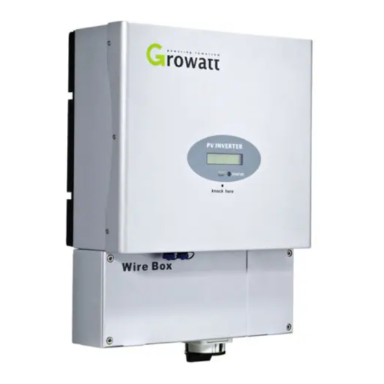
Page 7: Product Description
PV Grid Inverter PV Grid Inverter Model Name: Model Name: Model Name: 3.2 Information of Label Persons with limited physical or mental abilities may only work with the Growatt GROWATT 1500-US GROWATT 1500-US ********************** Range of input voltage: Range of input voltage:... -
Page 8: Storage Of Inverter
The unit must be stored in original package and desiccant must be left in the unpacking, please notify the shipping company and GROWATT NEW ENERGY package. -
Page 9: Installation And Electrical Connection
Both AC and DC voltage sources are terminated inside the PV Inverter. Please disconnect these circuits before servicing. Though the packaging box of Growatt is durable, please treat the This unit is designed to feed power to the public power grid (utility) packing box gently and avoid dispose the packing box. -
Page 10: Selecting The Installation Location
5.2 Selecting the installation location This is guidance for installer to choose a suitable installation location, to avoid potential damages to device and operators. Raintight or wet location hubs that comply with the requirements in the Standard for Conduit, Tubing, and Cable Fittings, UL 514B, are to be used. The unit shall be mounted at least 914 mm (3 feet) above the ground. -
Page 11: Mounting The Inverter With Bracket
There must be sufficient clearance between the individual inverters to ensure that the cooling air of the adjacent inverter is not taken in. If necessary, increase the clearance spaces and make sure there is enough fresh air supply to ensure sufficient cooling of the inverters. 5.3 Mounting the Inverter with bracket In order to avoid electrical shock or other injury, inspect existing electronic or plumbing installations before... -
Page 12: Fixed The Inverter On The Wall
After confirming the inverter is fixed reliably, fasten four M6 safety-lock Fix the mounting frame as the figure shows. Do not make the screws to sokets head cap screws on the left and right side firmly to prevent the be flush to the wall. Instead, leave 2 to 4mm exposed. inverter from being lifted off the bracket. -
Page 13: Intended Use
The unit converts the DC current generated by the photovoltaic (PV) modules to DC load circuit fuse or breaker grid-compliant alternating current and feed-in into the electricity grid. Growatt Growatt Inverter inverters are built according to all required safety rules. Nevertheless, improper use... -
Page 14: Connecting To The Grid (Ac Utility)
Connection of the AC cable Before wiring the inverter, the installer needs to determine the grid configuration that the inverter will be connected to. The Growatt inverter is default set for utility interconnection with 240Vac from factory. However, you can choose the Net MODEL through the LCD to set the inverter to be fitted the commonly used utility configuration types shown in the figure 5.6.3. - Page 15 3. installation rubber pipe into the knock-out hole and pull the pipe nut We suggest the AC separate unit spec as follow: slightly, feed the cables through the pipe into the wire box till the terminal Model Growatt Growatt Growatt 1500-US 2000-US 3000-US Grid type @208Vac 10A/400Vac 15A/400Vac 20A/400Vac @240Vac...
- Page 16 The AC side terminal is clear, Connect cables into relevant terminals as the figure 5.6.3 Cable requirements Product Model Area(mm²) AWG No. Growatt1500-US 3.33~5.26 10~12 Growatt2000-US 3.33~5.26 10~12 Input connection terminal Growatt3000-US 3.33~5.26 10~12 Suggestions for the PV modules of the connected strings: Same type Same quantity of PV modules connected in series Wiring inverter in parallel...
- Page 17 10~12 Wiring step: Growatt3000-US 3.33~5.26 10~12 1.Open the independent DC separate unit ,the DC switch on the Growatt -US inverter and the AC separate unit. 5.7 Commissioning Checking 2.Open the left hand side knock-out hole. Cover the wire box. Close the DC separate unit and the DC switch on the inverter.
-
Page 18: Lcd Display
LCD display LCD display 6.1 Display and messages 6.1.1 LCD display Glossary Starting-up display sequence, Once the PV power is sufficient, Inverter displays information as shown in the flow chart as follow: Abbreviation for "Alternating Current". Module: xxxxxx Ser No: xxxxxxxxxx FW Version: x.x.x Abbreviation for "Direct Current". - Page 19 Error: Power : 2016.2w Program State Programming Update Software The grid system AC: 241V F: 60.0Hz While Growatt inverter is working, the first line will Power : 2019.5w normally show Power status: Set Language Set Language Power : 2016.4w AC:241V...
-
Page 20: Setting The Lcd Display
Communications Communications 6.2 Setting the LCD display The inverter can support three kinds of knock: single knock, double knock. Each kind Power : 2016.2w : of knock has different function. Refer to specified definition in Table below Model: 2 Knock type Definition Single knock Key Down... - Page 21 7.1.2 Shine Vision 7.1.4 Shine Webbox Shine Vision, which consists of a power monitor and a number of transmitters, can Shine WebBox is specially designed for solar power plant remote monitoring. While achieve 1 to 6 monitoring modes. The transmitters transmit the power data collected supporting both wired and wireless communication, Shine WebBox can from a photovoltaic inverter to the monitor and display the data onto the monitor simultaneously monitor, record and analyze inverter operating parameters real time...
- Page 22 Through RS485 interface-Data logger 7.3 RS485 cable connection 1. Unscrew the plastic connector. 2. Make the RS485 cable go through the connector. Through RS485 interface-Data logger+ PC 3. Put two heat shrink tubes onto the front head of RS485 cable. Through RS485 interface-RS485-232 converter+ PC 4.
-
Page 23: Start-Up And Shut Down The Inverter
5. Make the heat shrink tubes wrap the joint. 7.4 Using shine tool to set the information of the inverter About the software of shine tool and the usage of it please download from the web: www.ginverter.com/Download.aspx Start-Up and shut down the inverter Start-Up and shut down the inverter 5. - Page 24 10.2 Packing the Inverter 9.3 Checking the DC switch If possible, always pack the inverter in its original carton and secure it with tension Check for externally visible damage and discoloration of the DC disconnect and the belts. If it is no longer available, you can also use an equivalent carton. The box must cables at regular intervals.
-
Page 25: Troubleshooting
2.5V reference 1.Restart inverter voltage fault 2.If error message still exists, contact Growatt. Sometimes, the PV inverter does not work normally, we recommend the following solutions for common troubleshooting. The following table can help the technician Error: 101 Communication fault 1.Restart inverter... -
Page 26: Operation Modes
NOTICE 12.2 Fault Mode This certificate represents a 10 year warranty for the Growatt inverter products listed below. Possession of this certificate validates a standard factory warranty of 5 years The internal intelligent controller can continuously monitor and adjust the system from the date of purchase. -
Page 27: Warranty Conditions
The liability of Growatt in respect of any defects in its PV inverters shall be limited to ,... - Page 28 Efficiency Model Growatt Growatt Growatt Max. efficiency 1500-US 2000-US 3000-US Specifications CEC efficiency 96.5% 96.5% Input data MPPT efficieny 99.5% 99.5% 99.5% Max. DC power 1800W 2300W 3200W Max. DC voltage 450V 500V 500V Protection devices DC reverse polarity 150V...
-
Page 29: Efficiency Curve
Relative humidity Consumption: night < 0.5 W < 0.5 W < 0.5 W Topology transformerless transformerless transformerless Cooling concept Natural Natural Natural Type 3R Type 3R Type 3R Enclosure Features DC connection: Screw terminal Screw terminal Screw terminal AC connection Screw terminal Screw terminal Screw terminal... -
Page 30: Download Address
Download Address Download Address www.ginverter.com/Download.aspx Contact Contact If you have technical problems about our products, contact the Growatt Service line. We need the following information in order to provide you with the necessary assistance: Inverter type Serial number of the inverter...
Need help?
Do you have a question about the 2000-US and is the answer not in the manual?
Questions and answers