
Related Manuals for Emerson iPro.Genius


Summary of Contents for Emerson iPro.Genius
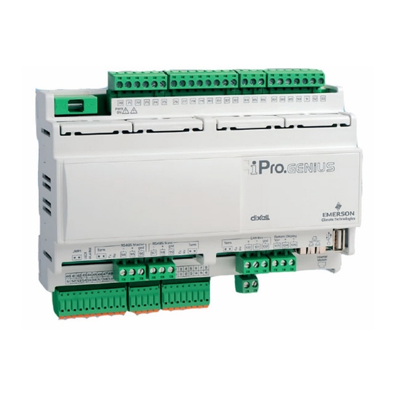
- Page 1 Discharge Air Controller (DAC) Installation and Operational Manual FW Version 1.04F05 026-1727 Rev 3...
- Page 3 Emerson 1065 Big Shanty Road NW, Suite 100 Kennesaw, GA 30144 770-425-2724 • www.emerson.com...
-
Page 5: Table Of Contents
Contents 1 INTRODUCTION................................1 1.1. T DAC’ I/O P ............................... 1 OINTS 1.2. I ..........................1 NDEPENDENT YSTEM ONTROL 2 MOUNTING AND POWERING ..........................2 2.1. I ................................2 NSTALLATION 2.2. P DAC..............................2 OWERING THE 2.2.1. Choosing Transformer Sizes ..........................3 2.2.2. - Page 6 7.4.3.3. Heating OAT Lockout ..............................18 7.5. F ................................18 ONTROL 7.5.1. CAV Mode ................................19 7.5.1.1. Variable-Speed Fan Control in CAV..........................19 7.5.1.2. Single Speed with Bypass Damper ........................... 19 7.5.1.3. Variable-Speed Fan Control in VAV..........................19 7.5.2. Fan Proofing ............................... 20 7.6.
- Page 7 10.2. V I/O C ..........................38 IEWING ONFIGURATION 10.2.1. Analog Inputs ..............................38 10.2.2. Relay Outputs..............................39 10.2.3. Analog Outputs ..............................39 10.2.4. Digital Inputs ..............................39 10.3. R ......................39 ELAY UTPUT VERRIDES WITH ISOGRAPH 10.3.1. Analog Output Overrides with Visograph ......................40 10.3.1.1.
-
Page 9: Introduction
Introduction 1.1. The DAC’s I/O Points The compact size of the DAC allows technicians The Discharge Air Controller (DAC) to field-mount the DAC in a rooftop unit or enclosure (P/N 818-9001) is a packaged HVAC control board close to it, allowing for local connection of sensors for use either as a standalone controller or in zone and transducers. -
Page 10: Mounting And Powering
Mounting and Powering The DAC is usually mounted by the HVAC equipment manufacturer. Therefore, the installer need only make the necessary connections between the boards and the site controller(s). In some instances, an installer may be required to mount the DAC. There are no restrictions on the location of the DAC;... -
Page 11: Choosing Transformer Sizes
2.2.1. Choosing Transformer Sizes 2.2.3. Wire Types and Maximum Distances The transformer used to power the DAC should have at least a 20VA rating. The DAC should not For powering I/O boards, use only the listed wire share a transformer with any other devices. types in Table 2-3. -
Page 12: The Modbus Network
The MODBUS Network If the recommended cable is not available in your area, be sure the wiring meets or exceeds the following specs: Although the DAC can operate as a stand-alone Shielded? controller, it relies on an E2 unit for advanced features such as remote dial-in/dial-out, logging, and alarm Twisted Pair Conductor Type... -
Page 13: Network Addressing - Visograph
3.1.2. Network Addressing - Visograph The network address makes a board unique from other boards on the network of the same type. This allows the site controller to find it and communicate with it easily. The network address of the DAC is set using add- on devices called visographs (P/N 318-7272). -
Page 14: Modbus Termination
Input and Output Setup should start blinking. Using the UP and DOWN arrows (T4 and T5), change the address to the desired value. Press ENTER to save new address.The ad- 4.1. The DAC Inputs dress field should stop blinking. Press MENU (T1) to go back to main menu. NOTE: When the MODBUS address is changed, the DAC will automatically reboot. -
Page 15: Wiring Analog Inputs On The Dac
Analog Input Type Description Point Digital Input Description Number Local or Outside Air Network Temperature VFD Alarm Variable Frequency Drive Alarm Return Air Temp Local Local Return Air Temperature Sensor Local Exhaust Hood Exhaust Hood Sensor Setpoint Reset Local Local Setpoint Reset (slider) Slider... -
Page 16: Wiring Digital Inputs On The Dac
Probe Input 2 Probe Input 3 Probe Input 4 Probe Input 5 Temperature Common 24VAC Supply + Figure 4-5 - Transducer Wiring for +12V Powered Devices Probe Input 6 Probe Input 7 CAUTION! Mis-wiring a sensor to the wrong common can result in damage to the DAC. Probe Input 8 Probe Input 9 Probe Input 10... - Page 17 Figure 4-8 - Digital Inputs Digital Input 16 (unsupported) Terminal Number on Digital Input 17 Name Connector (unsupported) Digital Input 1 Digital Input 18 (unsupported) Digital Input 2 Digital Input 19 Digital Input 3 (unsupported) Digital Input 4 Digital Input 20 Digital Input 5 (unsupported) Digital Input 6...
-
Page 18: The Dac Outputs
The DAC supports the following analog outputs: 4.2. The DAC Outputs Analog Output Description Relay Outputs Mod Fan (VS) Modulating Fan Mod Cool (2) Modulating Cool Stages (including Digital Scroll compressors) Mod Heat Modulating Heat Mod Outdoor Air Modulating Outdoor Air Damper Damper Mod Return Air... -
Page 19: Wiring Analog Outputs On The Dac
4.2.2. Wiring Analog Outputs on the The normally-open relay outputs on each connector share the same common and are not fused. Make sure to use the same voltage for all loads connected to the relays. The analog outputs are located on a separate 12- pin connector. - Page 20 Analog Output 4 Analog Out Common Analog Output 5 Analog Output 6 24VAC or 24VDC(-) 24VAC or 24VDC(+) Analog Out Common Table 4-8 -Digital Relay Output Connector Terminal Numbers 12 • The DAC Outputs 026-1727 Rev 3...
-
Page 21: Wiring Connection To Site Supervisor
Wiring Connection to Site Supervisor Figure 5-1 - Site Supervisor Wiring Discharge Air Controller (DAC) Manual Wiring Connection to Site Supervisor • 13... -
Page 22: Dac Status Leds
DAC Status LEDs When a DAC board is powered up, you will be able to determine the operating status of the board by observing its status LEDs. Figure 6-1 - DAC Status LED Locations 6.1. PWR ON LED 6.3. LED1 Network Status The PWR ON LED stays on continuously to show The amber colored LED1 indicates whether the that the board is powered and operational. -
Page 23: Software Overview
Software Overview Also, VAV mode does not require a local space sensor to be connected to the controller. Instead, the system terminal load is calculated by the E2 and is The DAC maintains space temperature setpoints sent over the network to the DAC so the operational by modulating heating or cooling stages to maintain a mode can be determined. -
Page 24: Space Temperature Control
the active setpoint. Conversely, when cooling mode is active, the controller will use the supply temperature 7.3. Space Temperature cooling setpoint as the active supply temperature Control setpoint. Cool stages will be turned on to maintain the supply air temperature at the active setpoint. There are two active space temperature setpoints 7.4.1. -
Page 25: Modulating Cooling
7.4.3. Heating Mode 7.4.2.1.2. Staging Off When the current supply air temperature drops The DAC supports both staged and modulating below the active supply air cooling setpoint minus the mechanical heating devices. A modulating device, Cool Stage Deadband, cooling stages will begin to such as a hot water valve, is treated as a heating stage stage off. -
Page 26: Modulating Heating
7.4.3.2. Modulating Heating will be used to determine the capacity output. If the modulating heat output reaches 100% and stays there In addition to the primary and secondary heat for the Heat On-Delay period, the first secondary stages, the DAC supports one modulating heating heating stage will be activated. -
Page 27: Cav Mode
7.5.1. CAV Mode 7.5.1.1.3. Make-up Air Offset VS Fan Speed When make-up air is active, the current VS fan The indoor fan will be controlled in one of three speed will be increased by the Make-up Air Offset% ways: setpoint. •... -
Page 28: Fan Proofing
setpoint, the VS fan will increase in speed (reverse depending on the dehumidification method selected. acting). A user parameter will specify the minimum A dehumidification RH or dewpoint throttling range speed that the VS fan is allowed to operate at when will determine the range of humidity or dewpoint that active. -
Page 29: Digital Scroll Operation During Dehumidification
calculated dehumidification load. In all units, the first until the return air bypass damper reaches 100%. cooling stage will activate once the load reaches 20%. Once activated, the Reheat output will remain active As the dehumidification load increases, it will be until the space temperature either rises above the distributed proportionally across cooling stages based cooling space temperature setpoint, or falls below the... - Page 30 multiplier setpoint. For example, if the RAB damper is at 50% and the RA damper multiplier is 10%, the RA damper will close an additional 5% from its current position. 22 • Dehumidification Control 026-1727 Rev 3...
-
Page 31: Outside Air Control
7.7.3. Economizer Control 7.7. Outside Air Control Economizer dampers on rooftop HVAC units are used to bring outside air into the building for use in The outside air damper can be used for several cooling. The DAC supports control of two-position strategies. -
Page 32: Economization Enabling Strategy
7.7.3.3. Economization Enabling economization will be enabled. If the outside temperature sensor fails, economization will Strategy be disabled. When communicating with the E2, the DAC only E2 Zone Enable (BAS) – This method is allows economization if it receives an economizer always used when the DAC is connected to enable signal from the E2. -
Page 33: Reversing Valve Control
assist in the dehumidification process. See Section 7.5.1.1., Variable-Speed Fan Control in 7.10. Control Temperature CAV for more details. Sensor Failures 7.8. 6.10 Reversing Valve In many cases, the DAC can compensate for sensor failures by substituting other sensor values. Control This allows the DAC to continue operating as close to normal as possible until the failed sensors can be fixed... -
Page 34: Dac Sensor Calibration Offsets In E2
sensors are available, economization will be locked OFF and the damper will be closed until the sensor 7.11. DAC Sensor Calibration failures can be addressed. Offsets in E2 Inside Humidity Failure The DAC will use the local indoor humidity sensor if it is defined. If no local indoor humidity sensor is defined, the DAC will use the indoor humidity value received from the E2. - Page 35 Enter the appropriate offset value (Figure 7-9). iProDAC Status Screen - Press F5 Figure 7-7 - Sensor Offset Properties in E2 - C0: MORE Figure 7-9 - Press % SETUP to access the iProDAC Setup screen (Figure 7-8). Press Ctrl + 0 and select F Sensor Offsets or ...
-
Page 36: E2 Setup
E2 Setup 8.1. Network Connection to E2 The DAC is capable of communicating with an E2 E2 PIB COM PORT ASSOCIATIONS version 3.0 or above. Using DAC with a central E2 offers several E2 Enclosure (Right Side) benefits over simple standalone control, including: E2 Modem/Expansion •... -
Page 37: Setup Network Ports
termination jumpers to the TERMINATED & BIASED position (all three jumpers UP); otherwise, 8.2. Add and Connect DACs set all jumpers DOWN if not the first device. To enable communications between E2 and the 8.1.1. Setup Network Ports DAC units, the devices must be added and addressed in E2. - Page 38 iProDAC001. allows you set the address:. Network Summary Screen Figure 8-4 - Figure 8-6 - Set the Address of the DAC 6. By default, each DAC’s board number in the 8. When finished, press to return to the Network network list is indicated by a - (dash).
-
Page 39: Viewing The Dac Status Screen
Network Summary Screen Figure 8-7 - 8.3. Viewing the DAC Status Screen Once you have added an DAC to the E2, you will be able to see the status of the DAC board(s) from the front panel. 1. From the Main Status Screen, press key and ... -
Page 40: Connections
Connections Connector Function RS485 Master connector Rx and Tx LED to indicate that communication is active 9.1. The DAC Connector Closed circuit terminal (Term) Descriptions Digital relay outputs (for digital outputs with volt-free contacts) 3 NO relays, 1 common Connector Function Digital relay outputs (for digital Connector for 24VAC/DC power... -
Page 41: Terminal Number Descriptions
9.2. Terminal Number Descriptions Terminal Type of Input Description Supply Power 24VAC or 24VDC(-) Analog Input 1 (Temperature, 0-10V, 0-1V, 0-5V) Analog Input 2 (Temperature, 0-10V, 0-1V, 0-5V) Analog Input 3 (Temperature, 0-10V, 0-1V, 0-5V) Analog Input 4 (Temperature, 0-10V, 0-1V, 0-5V) Analog Input 5 (Temperature, 0-10V, 0-1V, 0-5V) Common for temperature inputs (DO NOT TIE TO GROUND) Additional power reference 5VDC and 12VDC and analog inputs (0 -10V, ... - Page 42 Opto-insulated digital input 8 Opto-insulated digital input 9 DI10 Opto-insulated digital input 10 GND(-) Common opto-insulated digital inputs 1 to 20 (inputs 24VAC or 24VDC) (unsupported) DI11 Opto-insulated digital input 11 (unsupported) DI12 Opto-insulated digital input 12 (unsupported) DI13 Opto-insulated digital input 13 (unsupported) DI14 Opto-insulated digital input 14...
- Page 43 Not Used RS485 Master RS485 Master connection (-) RS485 Master RS485 Master connection (+) RS485 Master RS485 Master connection (insulated gnd) RS485 Slave RS485 Slave connection (-) RS485 Slave RS485 Slave connection (+) RS485 Slave RS485 Slave connection (insulated gnd) CAN Bus CAN Bus connection (+), not open CAN Bus...
-
Page 44: Technical Specifications
9.3.2. Digital Inputs 9.3. Technical Specifications Type: Opto-insulated volt-free 9.3.1. Analog Inputs (configurable via External power 24VAC/DC software ±20% parameter) Analog conversion 10-bit A/D converter type: Number of inputs: 20 Number of inputs: 10 Digital input status 250ms variation detection Type of analog NTC Dixell (-50T110°C;... -
Page 45: Analog Outputs
9.3.3. Analog Outputs 9.3.4. Digital Outputs Type: Opto-insulated with separate Type: Relays with NO contacts 24VAC/DC power supply Number of 10 or 15, depending on the Number of out- outputs: model puts: Type of output: Relays with normally open Type of analog 4 fixed outputs 0-10VDC (Out1 (configurable via contact... -
Page 46: Wiring
9.4. Wiring Figure 9-1 - DAC Detail NOTE: DI11 through DI20 (pins 51-60) are not available for use in the DAC controller. 38 • Wiring 026-1727 Rev 3... -
Page 47: Using The Visograph
Using the Visograph 10.1. Viewing Status For visograph button functionality, see Section 3.1.2.2., Visograph Navigation section. 10.1.1.Input Status From the main menu, select 1 to navigate to Figure 10-2 - Status - Outputs the status screens The status of the most common DAC inputs 10.1.3.VAV Fan Status are shown on this screen When the application is set to VAV, this screen... -
Page 48: Relay Outputs
Figure 10-4 - I/O Config - Analog Inputs Figure 10-6 - I/O Config - Analog Outputs 10.2.2.Relay Outputs 10.2.4.Digital Inputs Press the RIGHT arrow to navigate to the digital Press the RIGHT arrow to navigate to the inputs configuration screen. The configuration of all relay outputs configuration screen. -
Page 49: Analog Output Overrides With Visograph
Use the UP and DOWN arrows (T4 and T5), to change the override state to the desired val- ue. The choices are Auto, ON, and OFF. Press ENTER to activate the new override state. Press MENU to go back to main menu screen. -
Page 51: Index
Index Inputs 6 Installation 2 LEDs 14 MODBUS 4 Addressing iPro DAC 5 Termination 6 Analog Inputs 6 Wiring 4 Analog Outputs 10 MODBUS 485 4 Application Mode 15 MODBUS Addressing for iPro DAC 5 AWG 3 MODBUS Network 4 Modes 15 CAV 15 Mounting and Powering 2... - Page 52 VAV 15 VAV Mode 15 Visograph 38 Analog Output Overrides 39, 40 Buttons 5 Clear Analog Output Override 40 Connectivity 5 Override Analog Output 40 Relay Output Overrides 39 VAV Fan Status 38 Viewing I/O Configuration 38 analog inputs 38 analog outputs 39 digital inputs 39 relay outputs 39...
- Page 54 Emerson Climate Technologies Retail Solutions, Inc. and/or its affiliates (collectively “Emerson”), reserves the right to modify the designs or specifications of such products at any time without notice. Emerson does not assume responsibility for the selection, use or maintenance of any product. Responsibility for proper selection, use and maintenance of any product remains solely with the purchaser and end-user.
Need help?
Do you have a question about the iPro.Genius and is the answer not in the manual?
Questions and answers