Table of Contents
Advertisement
Quick Links
Advertisement
Table of Contents

Related Manuals for Emerson IC200CX EVO


Summary of Contents for Emerson IC200CX EVO
- Page 1 IC200CX EVO user manual...
-
Page 3: Table Of Contents
SUMMARY 1. Summary 8.7 Visualisation of compressors discharge temperature..27 8.8 Visualisation of condenser fans............28 2. User interface 8.9 Visualisation of proportional outputs / inverter.....28 2.1 Onboard keyboard..................5 8.10 Visualisation of defrost timings............28 2.2 Display and icons..................5 8.11 Visualisation of auxiliary inputs probes........28 2.3 Display visualization.................6 8.12 Visualisation of remote keyboard probes........29 2.4 Key functions....................7 8.13 Visulisation of the electronic thermostatic drive values.29 2.5 Key combinations..................8 8.14 Disableenable a single pumps............30 2.6 Remote terminal..................8 9. Domestic hot water production 3. Unit ON/OFF 9.1 Units with a single userside exchanger........31 3.1 ON/OFF by digital input................9 9.2 Units with a dedicated DHW heat exchanger (DWS)..32 3.2 ON/OFF by keyboard................10 9.4 Digital input for DHW double set point (option)....33 3.3 ON/OFF by remote supervision............10 9.3 Digital input for domestic hot water production only..33 9.5 Antilegionella function (optional)...........34 4. Cooling/heating operation mode 4.1 Mode change by digital input............11 10. Parameter programming 4.2 Mode change by keyboard..............12 10.1 Programming from keyboard............35 10.2 How to enter in programming mode in level Pr1....35 5. Visualisation of probes values 10.3 How to enter in programming mode in levels Pr2Pr3...37 10.4 How to change the value of a parameter........37 6. Set point 6.1 Set point visualisation................15 11. Functions 6.2 Modify the set point.................16 11.1 Compressor management ...............39 6.3 Double set point by digital input............17 11.2 Compressors management during DHW production..40... -
Page 4: Summary
SUMMARY The IC200 evo series controllers are dedicated to the management of heat pump units and chillers. They are characterized by compactness, extreme flexibility, control of the drivers for the management of electronic thermostatic valves and advanced functions such as domestic hot water production. Main functions: • Management of scroll and reciprocating compressors, with partializations or modulated by inverter • Compressor rotation control (also from n ° starts / hour) • Alarm history (alarm type, date, time, unit status) • Function of capacity control of the unit in critical operating conditions • Forced defrost in critical conditions • Combined temperature / pressure defrost • Domestic hot water production • Dynamic set point • Time bands management • Second set point (by time bands or digital input) • Analog outputs for condensation / evaporation control • RS485 and/or TTL serial output convertible into RS485 with ModBUS protocol • Quick release connections on all models • LAN output for connection to I/O expansion modules or EEV drivers IC200CX EVO user manual... -
Page 5: User Interface
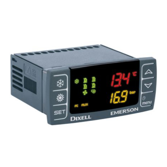
USER INTERFACE 2.1 Onboard keyboard The user interface consists of an onboard keyboard with a twoline and sixbutton LCD display. Through the display you can view the values measured by the unit probes, the status of the physical outputs as well as informations about the unit (number of operating hours, number of compressor starts) and faults. Authorized personnel can access to password protected parameters programming, e.g. change unit settings or enable additional functions. The activation of the main components (compressor, fan, pump, heater) is indicated by icons. load status (compressors, fans, pumps) temperature unit of measure clock working mode icons alarms and flow pressure unit of measure switch active functions 2.2 Display and icons IC200CX EVO ON when a temperature or pressure is visualized user manual Real time clock: ON when the bottom display show the RTC ON during the programming with time based parameter value In function menu indicates the defrost delay counting General alarm: blinking in case of alarm ON when domestic hot water production is active ON in defrost Blinking during defrost activation delay Antifreeze heaters/integration heating/boiler: ON if the heaters are switched ON Water flow alarm: blinking in case of water flow alarm Water pump: ON if at least one water pump is active... -
Page 6: Display Visualization
Condenser fan: ON if at least one condenser fan is active ON when the compressor is active Blinking = when a compressor activation is delayed (minimum OFF time, delay after water pump activation, etc.) ON when an auxiliary output is active ON if the unit is switched ON in cooling or heating 2.3 Display visualization All units are equipped with a digital input with remote on/off function (refer to the wiring diagram to identify the relevant terminals). The remote off contact has priority over the keyboard commands, i.e. it is not possible to start the unit from the keyboard (or from remote supervision via serial port) until the remote poweron contact is enabled (contact closed on the terminal board). The remote off unit status is indicated on the display by the label OFF with a flashing LED. After enabling the unit closing the remote on/off contact the display shows the label STBY (standby) until the desired operating mode is selected using the appropriate button (see below for details). IC200CX EVO user manual Once the unit has been started also from the keyboard, the upper line of the display shows the regulation probe (water inlet temperature at the main heat exchanger), while in the lower line the outlet water temperature is shown. -
Page 7: Key Functions
In addition to the basic visualizations (unit status, operating mode, input and output water temperatures) it is possible to read the values of all the temperature and pressure probes, the thermostatic valve driver probes and the operating parameters.The alarms are displayed by an icon and a flashing alarm code. The procedures for displaying and modifying parameters are described in detail in the following paragraphs. 2.4 Key functions heat pump mode up key chiller mode down key set point menu Push and release Show chiller set point SetC, heat pump set point SetH and sanitary set point SetS Push once again In chiller or heat pump if the Energy saving or the Dynamic setpoint are enabled it shows the real setpoint Setr. Push for 3 seconds Set point modification IC200CX EVO During the programming: push once user manual To enter parameter modification or confirm a value. Push when an alarm is showed To reset the alarm Push once with probe label showed on the bottom display (press up or down starting from default visualization) To read probes values of circuit 1 or circuit 2 Push once To read probes value Pushing once during the programming To change the group of parameters, to change the parameter, to change the value of the parameter Push for 1 second during the programming when the display visualize Pr1 or Pr2 or Pr3 1 time shows the Pr2 programming level 2 times shows the Pr3 programming level... -
Page 8: Key Combinations
Push once To read probes value Pushing once during the programming To change the group of parameters, to change the parameter, to change the value of the parameter Push once To turn ON or turn OFF the unit in heat pump mode Push once To turn ON or turn OFF the unit in chiller mode Push once To enter the function Menu Push for 3 seconds To set the clock Pushing once during the programming To exit from a group of parameter 2.5 Key combinations Push for 3 seconds together Enter in the parameters programming Push once together Exit the parameter programming IC200CX EVO user manual 2.6 Remote terminal The display visualization and the button functions are the same of the main controller, then refer to previous chapters of the manual. -
Page 9: Unit On/Off
UNIT ON/OFF The unit can be switched ON and OFF in several ways: • From digital input configured as remote ON/OFF • From the keyboard • From time bands • From remote supervision/XWeb 3.1 ON/OFF by digital input The ON/OFF digital input has priority over the keyboard. The unit can be switched ON and OFF from keyboard only if the unit is in ON mode by the input (contact closed). If you do not intend to use the remote ON/OFF function via digital input, identify the relevant terminals in the wiring diagram and jumper them (terminals 12). ON/OFF Warning: the ON/OFF input is in no case intended as an thermoregulation input, i.e. IC200CX EVO it should not be connected to external control units or thermostats used for user manual temperature control. For this use it is advisable to act on the Energy saving contact (see below). The typical use of the ON / OFF contact is to turn the unit on and off in predefined periods by means of external mechanical clocks or relay devices controlled by SMS. With the contact inactive (no With active contact (bridge in bridge in the terminal board) terminal block) the unit is the unit is switched off, the enabled in the last selected display shows OFF. operating mode (see below). -
Page 10: On/Off By Keyboard
3.2 ON/OFF by keyboard Press and release the heat pump mode key to turn the unit on in heating mode. Press and release the chiller mode key to turn the unit on in cooling mode. Note: with the unit in standby mode, i.e. activated by digital contact, but without ibeing switched on in chiller or heat pump mode, it is possible to view the measured variables through the display and manage the alarm situations by displaying and signaling them (see below) . When the unit is on, the mode LED indicates the functioning in chiller or heat pump, the pump icon turns on and then the operating icons of the condenser fans and the compressors are displayed. IC200CX EVO user manual 3.3 ON/OFF by remote supervision Switching ON/OFF, as well as complete management of the unit (change of mode, reading of temperatures, states, alarms, etc.) is possible via Modbus protocol on RS485 serial or via XWeb remote supervision system. Please refer to the dedicated manuals for details. -
Page 11: Cooling/Heating Operation Mode
COOLING/HEATING OPERATION MODE The change of the unit operating mode (chiller mode, heat pump mode) can occur: • From digital input configured as mode change • From keyboard Attention: the factory setting is "keyboard mode change" for units ordered with the optional remote keypad, and "digital input mode change" for units without this accessory. The configuration can be modified, i.e. the mode change can be performed by digital input even on units equipped with a remote keypad. 4.1 Mode change by digital input If you intend to use the function change mode via digital input, identify the relevant terminals in the wiring diagram (terminals 18) and connect them to an external selector. Warning: during the changeover phase make sure to stay within the operating limits of the unit. For example, changing the heat pump mode to the chiller mode could cause to enter in the unit previously heated water above the limits allowed in the in cooling mode, causing malfunctions. It is strongly advisable to perform a unit stop with an appropriate duration before proceeding to change the operating mode. IC200CX EVO user manual mode With the contact inactive (no With active contact (bridge in bridge in the terminal board) terminal block) the unit is in the unit is in chiller mode. heat pump mode. -
Page 12: Mode Change By Keyboard
4.2 Mode change by keyboard It is possible to switch from heat pump mode to chiller mode only by switching off the unit. If the unit is in heat pump mode, press the button to place it in Standby. Then press to switch it on again in chiller mode. Vice versa, if the unit is in chiller mode, press to place it in Standby, and then press to turn it back on in heat pump mode. IC200CX EVO user manual... -
Page 13: Visualisation Of Probes Values
VISUALISATION OF PROBES VALUES Pressing or the current probe values are displayed. Each selected probe can be identified by the corresponding label displayed on the display: EIn temperature of the water entering in the main heat exchanger EOut temperature of the water leaving in the main heat exchanger Et external air temperature IC200CX EVO user manual San1 sanitary water temperature... - Page 14 CdP1 condensation pressure circuit 1 CdP2 condensation pressure circuit 2 Note: press the button to change the visualisation of the condensation pressure value between the two circuits. LP1 evaporation pressure circuit 1 LP2 evaporation pressure circuit 2 Note: press the button to change the IC200CX EVO visualisation of the condensation pressure value user manual between the two circuits. Note: further values (discharge temperature, thermostatic valve electronic driver values, proportional outputs of the condensation fans and of the inverter, etc.) are available in the various sections accessible via the button . For details, refer to chapter 8.
-
Page 15: Set Point
SET POINT The set point indicates the working temperature set on the unit. The control probe for the chiller and heat pump modes is the input temperature in the main heat exchanger (i.e. the return temperature from the system), indicated in red on the first line of the display. The control probe for the production of domestic hot water (accessory) must be positioned by the installer in the storage tank. Its value can be displayed by selecting the SAn1 label using the arrow keys (see previous chapter). 6.1 Set point visualisation Press and release the button ; the leds of the circuits are off and the set value is displayed. When the unit is in standby, pressing once the lower display will show SetC (set chiller). Pressing the key again SetH (heat pump set) will be shown. If the domestic hot water is managed, the relative set point will also be displayed via the SetS label. The value of the set point is displayed in the upper row. IC200CX EVO user manual... -
Page 16: Modify The Set Point
When the unit is operating: when the button is pressed for the first time, the lower display shows SEtC (set chiller) or SEtH (set heat pump), depending on the unit mode, and the upper display shows the set value. Pressing again, with the energy saving or with the dynamic set point activated (par. 6.3), the lower display shows the label SEtr (real set) and the upper display shows the actual working set point of the unit. Press the button again to display the domestic hot water set point SEtS (if the function is activated). 6.2 Modify the set point The modification of the set point is only possible for the current unit mode (chiller or heat pump) and for domestic hot water management if active. Press for at least 3 seconds. 3 seconds The display will show SetC or SetH depending on the operating mode in the lower line. The blinking value of the set set will be displayed in the upper line. IC200CX EVO user manual Use the keys and to modify the set point value. To confirm the new set point, press or wait for the time out to exit programming. -
Page 17: Double Set Point By Digital Input
6.3 Double set point by digital input (optional) The double set point function (Energy Saving) allows to modify the regulation parameters via digital input (terminals 160). energy saving The Energy saving function is enabled when a digital input configured as “Energy saving” is active. When the Energy Saving function is active: • to the set point is applied an offset set by ES14 and ES16 parameters (different for cooling andheating); • the regulation differential is set by ES15 and ES17; standard differentials (St07 and St08 parameters) are not used if the Energy Saving is active If the Energy saving is active, the first pressure of button allows to read the set point set by parameter and second pressure allows to read the real set point (label Setr set modified by Energy saving finction). 6.4 Compensation of the set point based on the outside temperature (optional) The controller allows the working set point of the unit to be changed (compensated) automatically based on the outside air temperature measured by a probe installed on the machine.The summer set point and the winter set point can be compensated separately, whereas it is not possible to IC200CX EVO compensate the domestic hot water set point.For the settings of the dynamic set point, parameters user manual Sd01 to Sd06 must be changed and these can be accessed at user level (password 1) according to the settings indicated in the following sections. Please see the relevant section for the methods of accessing the parameters. Summer compensation In cooling mode, it is possible to increase/decrease the value of the working set point (parameter St01) by a value proportional to parameter Sd01. If parameter Sd01 assumes positive values, there will be an increase, and if it assumes negative values, there will be a decrease. The proportion of increase/decrease according to the outside air temperature value is controlled by a compensation start set point (parameter Sd03), and by the relevant differential (parameter Sd05) that can assume positive or negative values. The compensated value of the set point cannot exceed the limits of the working set point in chiller mode; it can therefore assume a value no lower than St02 and no higher than St03. When parameter Sd01=0 is set, the function is deactivated. - Page 18 Dynamic trend of the set point in cooling mode with positive compensation differential. Dynamic trend of the set point in cooling mode with negative compensation differential. Winter compensation In heating mode, it is possible to increase/decrease the value of the working set point (parameter St04) by a value proportional to parameter Sd02. If parameter Sd02 assumes positive values, there will be an increase, and if it assumes negative values, there will be a decrease. The proportion of increase/decrease according to the outside air temperature value is controlled by a compensation start set point (parameter Sd04), and by the relevant differential (parameter Sd06) that can assume positive or negative values. The compensated value of the set point cannot exceed the limits of the working set point in heat pump mode; it can therefore assume a value no lower than St05 and no higher than St06. IC200CX EVO When parameter Sd02=0 is set, the function is deactivated. user manual Dynamic trend of the set point in heating mode with positive compensation differential. Dynamic trend of the set point in heating mode with negative compensation differential...
-
Page 19: Alarms
ALARMS The unit anomalies are visualized in the lower line of the display through alarm codes, composed of letters and numbers that identify the different types. 7.1 Unit alarms type "A" Unit alarms these alarms can shut down the whole unit (e.g.. AEFL evaporator water flow switch): TABLE OF SHUT DOWN OUTPUTS FOR UNIT ALARM TYPE “A” Alarm code Description Compressor Antifreeze heater/ Support heaters Evaporator Condenser pump Condenser Auxiliary relay boiler pump ACF1 Configuration alarm AC14 Condenser flow alarm ACFL OFF (3) Eeprom alarm AEFL Evaporator flow alarm OFF (boiler) OFF (3) Sanitary water pump AHFL... - Page 20 Serial communication failure with I/O ASLA expansion Sanitary water pump AtAS overload OFF (6) Condenser water AtC1 pump 1 overload OFF (4) Condenser water AtC2 pump 2 overload OFF (4) Evaporator water AtE1 pump 1 overload OFF (4) OFF (boiler) (5) alarm Evaporator water AtE2...
-
Page 21: Circuit Alarms Type "B
7.2 Circuit alarms type "B" Circuit alarms can shut down the circuit involved (e.g.. b1HP high pressure switch circuit 1): TABLE OF SHUT DOWN OF OUTPUTS FOR CIRCUIT ALARM TYPE “B” Alarm code Description Compressors Compressors of other Condensing fans Condensing fan other circuit (n) circuit circuit (n) circuit Anti-freeze in chiller mode circuit (n) b(n)AC Anti-freeze warning in chiller mode circuit (n) b(n)Ac Anti-freeze in heat pump mode circuit (n) b(n)AH Anti-freeze warning in heat pump mode circuit b(n)Ah... -
Page 22: Compressor Alarms Type "C
7.3 Compressor alarms type "C" Compressor alarms can shut down the compressor involved (e.g. C1dt high discharge temperature compressor 1): TABLE OF SHUT DOWN OF OUTPUTS FOR COMPRESSOR ALARM TYPE “C” Alarm code Description Compressor (n) Compressors not involved Compressor high discharge temperature C(n)dt C(n)HP Compressor (n) high pressure switch Compressor (n) maintenance C(n)Mn Compressor (n) oil pressure switch / Oil level switch C(n)oP Compressor (n) oil differential C(n)Pd C( n )tr Compressor ( n ) overload... -
Page 23: Warnings
7.4 Warnings The warnings do not indicate anomalies that cause the unit to stop, they are mostly informative messages regarding the maintenance periods (e.g. AEP1 reaching the evaporator pump maintenance hours threshold 1): WARNINGS TABLE Code Description Condenser water pump 1 maintenance ACP1 Condenser water pump 2 maintenance ACP2 Evaporator water pump 1 maintenance AEP1 Evaporator water pump 2 maintenance AEP2 Unloading caused by evaporator high temperature AEUn Clock setting ArtC Clock failure ArtF... -
Page 24: Function Menu
FUNCTION MENU To access the functions menu, press and release the button. The list of functions can be scrolled cyclically using the or buttons. Confirm access to the desired function with the button. After entering the functions menu, you will be able to do the following: • View and reset the alarms present (ALrM) • View and delete the alarm log (ALOG) • Upload the parameter into the Hot Key (UPL) • Enable – disable one or the two circuits (CrEn) • Enable – disable one of the compressors (COEn) • Read and reset the number of compressor running hour (Hour) • Read and reset the number of compressor startsup (COSn) • Read the compressor discharge temperature (COdt) • Read the condensing fan speed percentage (Cond) • Read the percentage of the proportional outputs (Pout) • View time counting to next defrost cycle, under heat pump mode, (dF) • Read the probe temperatures enabled to control the auxiliary output (uS) • Read probe temperature of the remote panels VICX 620 (trEM) • Read temperature, pressure, set point of the electronic expansion valve 1 (Et1) • Read temperature, pressure, set point of the electronic expansion valve 2 (Et2) • Enable – disable evaporator or condenser water pumps (PoEn) 8.1 Alarm list (read and reset) IC200CX EVO The ALrM menu shows all the alarms present in the user manual unit. If the alarm is at automatic reset, the alarm ... -
Page 25: Alarm Log List
8.2 Alarm log list Within the ALOG menu the alarms are stored with increasing index use the arrow keys to scroll through the list; the upper line shows the "n" label followed by the progressive number from 00 to 99, while in the lower line the alarm code is displayed. Press the key to access the data stored in the alarm history: the first screen shows the alarm time and the operating mode of the unit. IC200CX EVO Pressing the date (year day month) of the user manual alarm will be displayed. Press to return to the alarm log. -
Page 26: Disableenable A Circuit
8.2 Disableenable a circuit Through the CrEn menu it is possible to disable the operation of a single circuit from the keypad to allow maintenance of the same or a "partialized" operation of the unit. 3 seconds Enter the menu and press the key for 3 Note: during normal operation, seconds corresponding to the label Cr1E or Cr2E disabled circuits are signaled via the (circuit 1 / circuit 2). Use the arrow keys to select the b1dS or b2dS labels flashing on the diS (disabled circuit operation) or En (enabled circuit lower display. operation) label and press the key to confirm the function and move to the next circuit (only the loads relative to the circuit are disabled). 8.3 Disableenable a single compressor Through the COEn menu it is possible to disable the operation of a single compressor inside a circuit to allow maintenance of the same or isolate it in case of malfunction. IC200CX EVO user manual 3 seconds Enter the menu and press the key for 3 Note: during normal operation, seconds corresponding to the CO1E or CO2E label disabled compressors are signaled (compressor 1 / compressor 2). Use the arrow keys to via the C1dS or C2dS labels flashing select the label diS (compressor operation disabled) on the lower display. or En (compressor operation enabled) and press the key to confirm the function and switch to the next compressor. -
Page 27: Parameters Backup And Restore With "Hot Key
8.4 Parameters backup and restore with "Hot Key" Using the UPL menu, the instrument parameters can be stored in a "Hot Key" programming key. The key must be inserted when the instrument is switched on. Pressing the key the controller starts copying the data; the UPL label is flashing. When the procedure is completed, the END message is displayed confirming that the copy has been correctly executed, or Err in case of errors. 8.5 Visualisation of compressors and pumps operating hours Through the Hour menu it is possible to view the operating hours of the controlled loads: • compressors operating hours (CO1H/CO2H) • main pump operating hours (EP1H) • sanitary water pump operating hours (SAPH) Note: the hours of operation are shown in the upper display with a resolution of 10 hours (the value 2 indicates that the hours of operation of that load are 20). 8.6 Visualisation of compressors startsup Through the COSn menu it is possible to display the number of compressors startsup. The individual compressors are identified by the C1S and C2S labels. IC200CX EVO user manual Note: the startsup are shown in the upper display with a resolution of 10 (the value 2 indicates that the startsup are 20). 8.7 Visualisation of compressors discharge temperature Through the COdt menu it is possible to display the temperature value of the probes that control the compressor discharge temperature. • discharge temperature compressor n° 1 (CO1t) • discharge temperature compressor n° 2 (CO2t) -
Page 28: Visualisation Of Condenser Fans
8.8 Visualisation of condenser fans Through the Cond menu it is possible to visualize the working percentages of the condenser fans proportional outputs of the circuit n° 1 and n° 2. • condenser fans circuit n° 1 (Cnd1) • condenser fans circuit n° 2 (Cnd2) 8.9 Visualisation of proportional outputs / inverter Through the Pout menu it is possible to view the working percentages of the four proportional outputs. The configuration of the proportional outputs (inverter, speed controller, etc.) depends on the unit type refer to the relevant wiring diagram. • proportional outputs 14 (Pou1Pou4) 8.10 Visualisation of defrost timings Through the dF menu it is possible to view the time delay to next defrost. • delay time to next defrost of the circuit n° 1 (dF1) • delay time to next defrost of the circuit n° 2 (dF2) IC200CX EVO user manual 8.11 Visualisation of auxiliary inputs probes Using the uS menu it is possible to display the temperature / pressure value of the probes that control the auxiliary outputs. The function associated with the auxiliary outputs depends on the unit type refer to the relevant wiring diagram. • auxiliary ptobe 12 (uSt1uSt2) -
Page 29: Visualisation Of Remote Keyboard Probes
8.12 Visualisation of remote keyboard probes Through the trEM menu is possible to visualize the temperature detected by the remote keyboard onboard probe. • remote keyboard 12 onboard probe (trE1trE2) 8.13 Visulisation of the electronic thermostatic drive values Through the Et1 menu is possible to visualize the value of the probes connected to the electronic thermostatic valve driver, as well as other driver info. • thermostatic drive 12 informations (EtC1EtC2) The data that can be viewed are: IC200CX EVO user manual Current superheat set point (SEt) Current superheat value (SH) Thermostatic valve opening percentage (OPEn) -
Page 30: Disableenable A Single Pumps
Suction temperature (tASP) Evaporation pressure (PEuA) Evaporation temperature (tEuA) 8.14 Disableenable a single pumps Through the POEn menu it is possible to disable the operation of a single pump to allow maintenance of the same or isolate it in case of malfunction. IC200CX EVO • main pump (PE1E) user manual • sanitariy water pump (PSAE) -
Page 31: Domestic Hot Water Production
DOMESTIC HOT WATER PRODUCTION This configuration must be associated with a suitably sized boiler in which to store high temperature water. The boiler must have a well for insertion of the domestic hot water probe, placed at the top, through which the controller of the unit monitors the need to produce domestic hot water. The production of domestic hot water is indicated on the display by the symbol: 9.1 Units with a single userside exchanger For units with a single userside heat exchanger, the controller allows the sanitary hot water production function to be activated and managed with waterside valve. The following must be installed on the system: a 3way valve that diverts the flow of water to the user or sanitary hot water storage and a temperature probe that measures its value. The functionality allows the unit to control the temperature inside a storage tank for domestic hot water, through the domestic hot water probe, and to manage the 3way valve outside the unit. The priority is always for domestic hot water production. IC200CX EVO user manual Heat pump operation: the valve diverts the supply water to the system. The operating set is SetH (SetC if in chiller mode). Domestic hot water operation: the valve diverts the supply water towards the storage tank. The operating set is always SetS. -
Page 32: Units With A Dedicated Dhw Heat Exchanger (Dws)
The priority is always for domestic hot water production. The heat pump normally operates on the system to meet the comfort requirements of the system, but when the temperature of the water inside the tank falls below a set threshold (set point SetS, chap. 6), the control manages domestic hot water production: • if the unit is operating as heat pump for heating, the 3way valve will be switched and the set point changed; • but if the unit is producing chilled water for air conditioning, the control switches the unit to heat pump mode, gives it the set point for domestic hot water and diverts the 3way valve to the appropriate position. Once the temperature inside the domestic hot water tank has reached the set value, the unit automatically returns to producing water for the heating and air conditioning system. 9.2 Units with a dedicated heat exchanger for domestic hot water (DWS) The unit in this setup has two heat exchangers: a system side one, for air conditioning and heating, and one dedicated exclusively to domestic water production. IC200CX EVO user manual On the system side heat exchanger, the unit can produce hot water or cold water to meet the heating and cooling requirements according to the seasons. On the heat exchanger dedicated to domestic hot water, the unit produces high temperature water to be sent to a storage tank outside the machine. This tank has been selected and sized according to the requirements of the system. Depending on the season, the unit works with different modes: the change through the various operating modes (within the season) is carried out automatically through the reading of the temperature probes and the set points. Switching times and logics have been designed to ensure the maximum efficiency and reliability of the system. This configuration must be associated with a suitably sized boiler in which to store high temperature water. The boiler must have a well for insertion of the domestic hot water probe, placed at the top, through which the controller of the unit monitors the need to produce domestic hot water. -
Page 33: Digital Input For Dhw Double Set Point (Option)
9.3 Digital input for domestic hot water production only If the digital input configured as “Enabling of domestic hot water production only” (terminals 4001) is active, the controller is enabled for domestic hot water production only; thermoregulation for the production of hot or chilled water is disabled. sanitary only If the digital input is active, the unit can be switched on or put in standby by pressing button or (when switching off, the button pressed depends on the mode that was active when the digital input for domestic hot water production only was activated). When the digital input for domestic hot water production only is active the lower display shows the label “OSA” (Only SAnitary). 9.4 Digital input for domestic hot water double set point (option) IC200CX EVO The controller allows the domestic hot water working set point to be changed based on activation/ user manual deactivation of a suitably configured digital input (terminals 6101). double set sanitary When the value is active: • an offset of the value of parameter ES32 is applied to the DHW set point (parameter ES32 can assume positive or negative values, it can therefore assume a value no lower than FS05 and no higher than FS06); • the connection/disconnection differential of the compressors assumes the value ES33 ... -
Page 34: Antilegionella Function (Optional)
9.5 Antilegionella function (optional) The controller manages a weekly antilegionella cycle with the use of only electric heaters outside the unit; the compressors will remain switched off during the cycle. The antilegionella function can be activated by setting parameter FS12=1, and setting the day of activation (parameter FS18) and the start time (parameter FS17). To disable the function, set parameter FS12=0. The function is active with machine ON. If the antilegionella cycle request occurs while the machine is off, when it is next switched on, the controller will wait until the next weekly request time to immediately activate the antilegionella cycle. The function must remain active for the minimum time set on parameter FS19 (active from when the domestic hot water temperature reaches the antilegionella set point) and can last for a maximum time of FS29 minutes (the maximum operating time has priority over the minimum operating time; if the maximum time expires before the minimum time, the function will be exited). When the antilegionella cycle starts, all the heaters will be switched on to bring the water to set point; once the set point has been met, the heaters are switched off on reaching set point FS14+FS20. The antilegionella cycle is active for the minimum time FS19; during this time, the heaters regulate on the antilegionella set point FS14 and with control band FS04. During this procedure, the lower display will indicate the "LEG" label. IC200CX EVO user manual If the clock has an error, the function is disabled. Once this procedure has been completed, the controller will go back in domestic hot water production mode or normal thermoregulation mode. -
Page 35: Parameter Programming
PARAMETER PROGRAMMING 10.1 Programming from keyboard The values of all the parameters can be changed through the keypad. The parameters of the controller have been gathered into families, each of which is identified with a label. This enables the user to quickly access the parameters concerned in the various levels. • ALL All parameters • St Thermoregulation parameters • CF Configuration parameters • Sd Dynamic set point parameters • ES Double set point parameters • Cr Compressor control unit parameters (not used) • CO Compressor/pump parameters • US Auxiliary output parameters • FA Fan parameters • Ar Antifreeze heater parameters • Df Defrost parameters • FS Domestic hot water management parameters •... - Page 36 Using the or buttons, set the value of the password "1". Press the button to confirm. If the password is correct, the programming level is entered and the ALL label is displayed, otherwise the password is shown again. For the meanings of the various labels, see the beginning of the chapter. Use the arrow keys to switch between menu groups and the key to access. WARNING: With the unit running in chiller mode or heat pump mode, the values of the parameters contained in the CF family cannot be changed. During a defrost cycle, the values of the IC200CX EVO parameters contained in the dF family cannot be changed. dF. user manual In order to change the parameters, exit programming mode and put the unit in standby and then enter programming mode again.
-
Page 37: How To Enter In Programming Mode In Levels Pr2Pr3
10.3 How to enter in programming mode in levels Pr2Pr3 Simultaneously press the and buttons for 3 sec; the upper display shows the PAS label and the lower display shows the "Pr1" label (level Pr1). Press and hold the key for 3 seconds, the label "Pr2" will appear on the lower display (Pr2 level). 3 seconds 3 seconds Press and hold the key for another 3 seconds, the label "Pr3" will appear on the lower display (Pr3 level). 3 seconds The password is entered as in the case of access to the parameter level Pr1. 10.4 How to change the value of a parameter IC200CX EVO Enter the parameter programming as described in the user manual previous paragraphs, use the arrow keys to select the desired parameter group (eg St thermoregulation parameters). Confirm with . The first parameter of the selected group will appear, with its current value. - Page 38 Find the required parameter using the arrow keys. Confirm pressing . The parameter value will start to flash, and can be changed with the keys and . Press again to confirm the new value. To return to the main screen, press and hold the keys and for 3 seconds. IC200CX EVO user manual...
-
Page 39: Functions
FUNCTIONS 11.1 Compressor management The unit activates the compressors according to a proportional regulation with lateral band. In case of use of compressors with partialisations, each partialisation is seen as a step and the proportional band is divided by the total number of steps. The activation of the compressors respects the safety timing of the same (minimum ON time, minimum OFF time, minimum time between two starts of the same compressor, minimum time between the switching ON of two compressors, etc.). Compressor regulator diagram in cooling mode • St01 Set point, also accessible by key , SetC • St07 Cooling proportional band IC200CX EVO user manual Compressor regulator diagram in heating mode • St04 Set point, also accessible by key , SetH • St08 Heating proportional band... -
Page 40: Compressors Management During Dhw Production
11.2 Compressors management during domestic hot water production The regulation takes place on the set point for the production of domestic hot water (DHW) and with a proportional band that can be set by parameter (grouping of parameters FS); with the domestic hot water function active, the led of the domestic hot water mode and the led of the working mode (cooling or heating) are displayed. Compressor regulator diagram in DHW mode • FS03 Set point DHW, also accessible by key , SetS • FS04 DHW proportional band All’abbassarsi della temperatura dell’acqua sanitaria l’accensione dei compressori avviene in modo IC200CX EVO proporzionale rispetto al set point ACS. When the domestic hot water temperature decreases, the user manual compressors are switched on proportionally to the DHW set point. At the moment in which there is demand for domestic hot water production, an FS09 minute counter is active which determines the maximum time for reaching the domestic hot water setpoint; after this time all the compressors are inserted (if they were not already inserted). In case of an error of domestic hot water probe the DHW function is inhibited; the unit will however work normally in cooling or heating. If during the production of domestic hot water the main thermoregulation (main exchanger input probe) goes into error, there is no blockage of the unit but the cooling or heating thermoregulation will be disabled and DHW water production will remain active. -
Page 41: Water Pump, Function Pulse
11.3 Water pump, function pulse Per impostazione predefinita l'accensione della pompa dell’acqua dipende dallo stato del dispositivo: • Dispositivo spento pompa acqua spenta • Dispositivo acceso in riscaldamento o raffrescamento pompa acqua accesa Alla prima accensione della pompa dell’acqua, i compressori sono accesi solo se è trascorso il tempo impostato in CO17 dall'accensione della pompa. Posizionando l’unità in standsby o OFF remoto la pompa dell’acqua si spegne dopo il tempo impostato nel parametro CO18. La pompa è comunque spenta se in caso di allarme termica pompa acqua o in caso di allarme flussostato. Function pulse If the pump is off (due to thermoregulation or due to unit in Standby/ OFF), the controller, if correctly parametrised, can carry out periodic switchons of the userside pump to move the water inside the pipes and measure the control temperature or to prevent pump shutdown due to prolonged inactivity. To activate the function, set parameter CO16 = 2 (pump operation when requested by the compressor). When the unit is on, on reaching the set point, the controller will switch off the water pump and start it again at regular intervals for a sufficient time to measure its actual temperature. If the controller verifies that the unit is still in set point, it will switch off the pump again. If it does not, it will activate the compressor, and the pump will run continuously until the next time the set point is reached. When the unit is started, if there is no control request, the periodic switchon cycle of the water pump IC200CX EVO will be activated. user manual • CO69 pump switchon time (in multiples of 10 seconds) • CO67 pump switchoff time (in multiples of 10 minutes) If the unit is off, periodic switchons will be carried out to move the water inside the pipes to prevent pump shutdown due to prolonged inactivity. • CO69 pump switchon time (in multiples of 10 seconds) • CO68 pump switchoff time (in multiples of 10 hours) -
Page 42: Clock And Time Bands
11.4 Clock and time bands If giving power supply the bottom display shows “rtC” alternated with a temperature or pressure value, It is necessary to set the internal clock. Press the button: the hour starts to flash. 3 secondi Use the arrow keys to adjust it. Push one time to confirm; automatically the display shows next parameter. Repeat the operations for all the RTC parameters: Min: minutes (0÷60) UdAy: day of the week Sun = Sunday Mon = Monday tuE = Tuesday UEd = Wednesday tHu = Thursday IC200CX EVO Fri = Friday user manual SAt = Saturday) dAy: day of the month (0÷31) MntH: month (1÷12) yEAr: year (00÷99) Time bands With the controller internal clock, the second set point can be activated through time band instead of activation from digital input. It is also possible to set automatic switching on/off from time band. During activation of the double set point, the unit works at the following set point and differential values: • in chiller mode: set point St01 + ES14, differential ES15 • in heat pump mode: set point St04 + ES16, differential ES17 The working set point may be compensated based on the outside air if the relevant function is active. - Page 43 Parameters ES01 to ES13 must be suitably configured (time band start/end and day of activation). There are 3 settable time bands, and one or more time bands can be activated for each individual day of the week. Parameters ES01ES06 define the start and end of the 3 time bands. ES01 Start of time band 1 00:0024:00 ES02 End of time band 1 00:0024:00 ES03 Start of time band 2 00:0024:00 ES04 End of time band 2 00:0024:00 ES05 Start of time band 3 00:0024:00 ES06 End of time band 3 00:0024:00 Parameters ES07ES13 define activation of the time bands in the individual days of the week. ES07 Time bands activated for Monday ES08 Time bands activated for Tuesday ES09 Time bands activated for Wednesday ES10 Time bands activated for Thursday ES11 Time bands activated for Friday ES12 Time bands activated for Saturday ES13 Time bands activated for Sunday Parameters ES07ES13 are made up of a pair of values that have the following meaning. • The first value “X” represents enabling with time bands for double set point •...
- Page 44 Time bands for domestic hot water The second set point for domestic hot water production can be activated through time band instead of activation from digital input. Parameters ES19 to ES31 must be suitably configured (time band start/end and day of activation). During activation, the unit will produce domestic hot water on the working set point FS03+ES32 with differential ES33. There are 3 settable time bands, and one or more time bands can be activated for each individual day of the week. Parameters ES19ES24 define the start and end of the 3 time bands. ES19 Start of time band 1 for domestic hot water 00:0024:00 ES20 End of time band 1 for domestic hot water 00:0024:00 ES21 Start of time band 2 for domestic hot water 00:0024:00 ES22 End of time band 2 for domestic hot water 00:0024:00 ES23 Start of time band 3 for domestic hot water 00:0024:00 ES24 End of time band 3 for domestic hot water 00:0024:00 Parameters ES25ES31 define activation of the time bands in the individual days of the week. ES25 Time bands activated for Monday ES26 Time bands activated for Tuesday ES27 Time bands activated for Wednesday ES28 Time bands activated for Thursday ES29 Time bands activated for Friday ES30 Time bands activated for Saturday ES31 Time bands activated for Sunday...
- Page 45 Example of configuration • from Monday to Friday the unit is active from 6:00 a.m. to 8:30 and from 18:00 to 23:00 • Saturday and Sunday the unit is active from 7:00 to 23:00 At first step, 3 hours bands used need to be define throught parameters ES01ES06 from menu ES: Firts hour band definition, 6:008:30: Second hour band definition, 18:0023:00: IC200CX EVO user manual Third hour band definition, 07:0023:00:...
- Page 46 As second step the hours bands need to be assign to every week day through parameters ES07 ES13. Note: out of the time bands it is possible choose to switchoff the unit ( label Stby on display) or set the Energy Saving mode (refer par. 6.3). Time bands assignment to the single week day ON/OFF mode : • from Monday to Friday, bands 1 and 2 are active IC200CX EVO user manual • Saturday and Sunday only third band is active...
- Page 47 Time bands assignment to the single week day Energy Saving mode: • from Monday to Friday, bands 1 and 2 are active • Saturday and Sunday only third band is active IC200CX EVO user manual...
-
Page 48: Auxiliary Heat Source Function
11.5 Auxiliary heat source function The controller manages an external source that can be used as a supplement or backup to the heat pump when the outside air temperature is particularly harsh. The supplement/backup mode depends on the selection of parameter Ar11. To deactivate the function, set parameter Ar11 = 0 (level Pr2). The external source is switched off: • with a flow switch alarm active; • with evaporator pump overload protection alarm active; in this case, the boiler heaters are activated only by the antifreeze set point for exchanger protection. Supplement function To activate the function, set parameter Ar11 = 1. During operation, when the air temperature measured by the outside air probe falls below the outside set point value Ar12, counting of the delay time Ar14 begins. If, during counting of time Ar14, the outside air temperature rises above the value set in parameter Ar12 + differential Ar13, the function is cancelled and time Ar14 is reloaded. Diagram of consent to activation of the auxiliary source and the compressors based on the outside air temperature. IC200CX EVO user manual If, after time Ar14, the outside air temperature remains below set point Ar12 and the water temperature measured by the thermoregulation probe is lower than set point value Ar17, the heat source is enabled. With supplement function enabled (outside air temperature below value Ar12), if the outside air temperature falls below set point Ar19, the compressors are switched off. The compressors are switched on again if the outside air temperature returns above set point Ar19 + control band Ar20. When set point Ar17 + control band Ar18 is reached, the external source is switched off. - Page 49 Diagram of consent to activation of the auxiliary source based on the system water temperature. If, during operation with external source active, the outside air temperature exceeds set point value Ar12 + differential Ar13, this is switched off and time Ar14 is reloaded. Backup function To activate the function, set parameter Ar11 = 2 (default setting). During operation, when the air temperature measured by the outside air probe falls below the outside set point value Ar12, counting of the delay time Ar14 begins. If, during counting of time Ar14, the outside air temperature rises above the value set in parameter Ar12 + differential Ar13, the function is cancelled and time Ar14 is reloaded. Diagram of consent to activation of the auxiliary source based on the outside air temperature. If, after time Ar14, the outside air temperature remains below set point Ar12 and the water temperature measured by the evaporator thermoregulation probe is lower than set point value Ar17, the heat source is enabled and the compressor and condensation fan are switched off, and heating IC200CX EVO takes place only through the external source. user manual When set point Ar17 + control band Ar18 is reached, the external source is switched off. Diagram of consent to activation of the auxiliary source based on the system water temperature. If, during operation with external source active, the outside air temperature exceeds set point value Ar12 + differential Ar13, this is switched off and the compressor (observing the delay times) and the fan are switched on again and time Ar14 is reloaded.
-
Page 50: Visograph Keyboard 50
VISOGRAPH KEYBOARD 12.1 Visualization after the power on After the power on the system displays two buttons: ENTER Enter to the main visualisation Info Visualisation of the system informations (software release) Entering in the main visualisation it is possible to read: Unit status Status of the unit: cooling, heating, remote OFF or STD Date and time Available if the unit is provided by internal clock Main probes The displayed values change according to the model, they can however be configured using the parameters dP06..dP09. dP06..dP09 The load and the functions status are showed as in the table below: IC200CX EVO user manual Compressor/s (blinking during the start up Economy function active delay) Unloading function / power Water pump limitation Condenser fan - Economy or ON/OFF by N indicate that condenser fan timetable... - Page 51 Meaning of the keys: Allows to read the value of the Allows to read/modify the set probes configured on the unit. point Switch the unit on in heating Allows to read the alarms mode Switch the unit on in cooling Allows to enter in Service mode menu Allows to read the main...
-
Page 52: Probes Visualisation
12.2 Probe visualisation Press key to visualize the value of the probes configured on the unit (press or to visualize all the probes). 12.3 Set point visualisation and modification Press key to read the value of the set point (cooling set point if the Ichill is in cooling mode, heating set point if the Ichill is in heating mode, cooling and hating set point if the Ichill is in STD_BY or remote OFF, Domestic hot water when enabled). It is also possible to read the status of the Energy saving, the status of the Dynamic set point and the real value of the set point if the Energy saving or Dinamic set point are active. To modify the set point (Cooling, Heating or Domestic hot water): • use the keys to select the value of the set point • press • use the keys to modify the value • press to confirm the operation IC200CX EVO user manual 12.4 Alarm visualisation Press key to read the alarm status; the alarm status can be: Active the alarm is still active and it is not possible to reset it Reset the alarm is not active and it is possible to reset it Manual reset procedure: • use keys to select the alarm • press to reset the alarm ... -
Page 53: Circuit Informations
12.5 Circuit informations Pressing the key allows you to view the unit's main operating values in semigraphical mode. Use the keys to move between the masks. Pressing the key additional informations are displayed: the status of the compressors in each circuit, the water pumps, the condensation fans and the value of the pressure probes of each circuit. IC200CX EVO user manual The status of the loads is displayed as follows: Compressor OFF Compressor ON Condensation fan ON (speed Condensation fan OFF modulation) Water pump OFF Water pump ON... -
Page 54: Menu Service
Info screens examples: 12.6 Menu service From the main display, by pressing the key, it is possible to access the service menu where it is possible to modify the parameters, perform maintenance operations and view details relating to the unit. • use keys for move between icons • press to change page • press to select service functions IC200CX EVO • press for exit user manual... - Page 55 The meaning of the service icons is indicated in the table below: Parameter programming Programming clock, Energy saving and ON/OFF scheduling Compressor maintenance - it is possible to disable the compressor for maintenance, read the working hours and number of start up (and reset them) Water pump maintenance - it is possible to read / reset the working hours Circuit maintenance Visualization and reset of the alarms Visualization and reset of the alarm log...
- Page 56 Parameters programming Pressing it is possible to read/modify the parameters value: • select the level 1 (default) or level 2 or level 3 (by pressing Pr2 or Pr3 key) • press • use to enter password • confirm pressing • the display shows “Password OK!” (otherwise repeat the procedure) • press key to visualize the parameters • pressing or it is possible to select the group of parameters to modify, then press IC200CX EVO user manual • use the keys to select the parameter to modify • press • modify the value with keys • press to confirm • use to scroll the parameters...
- Page 57 Clock and scheduler programming Through the menu "Clock ans scheduler programming" it is possible to adjust the clock (for the device models that have the clock on board) and display the time bands linked to the Energy Saving and automatic shutdown functions. Compressor maintenance In the menu it is possible to visualize and reset the compressor working hours and the number of activations. It is also possible to disable the compressor for maintenance. Water pump maintenance IC200CX EVO user manual In the menu it is possible to visualize and reset the water pumps working hours. ...
- Page 58 Circuit maintenance In the menu it is possible to disable the circuit for maintenance; all the compressor will be switched off after disabling the circuit. Alarm visualization and reset In this menu you can view and reset the alarms in progress. Refer to section 12.4 for the details. Alarm log Pressing or it is possible to read the last 99 alarms. If the unit is equipped with a clock, the date and time of the alarm are also displayed. IC200CX EVO user manual Defrost status For each circuit it is possible to read the status of the defrost, the condenser pressure, the suction pressure, the defrost start temperature / pressure and the defrost end temperature / pressure.
- Page 59 Solenoid valve and heaters In this menu it is possible to read the status of the solenoid valves, boiler and antifreeze electrical heaters. I/O status In these screens you can view the status of all probes as well as digital I/Os. The I/Os of the expansion (if installed) are also listed. IC200CX EVO Auxiliary outputs user manual The auxiliary outputs of the control are used for regulation functions, the modification of the control parameters is reserved to the manufacturer.
- Page 60 Domestic hot water and antilegionella The masks allow you to view the settings and status of the DHW and antilegionella function. Parameters programming with the Hot Key With the Hot Key it is possible to copy or write a parameter map to the unit. Use is reserved for Service personnel. IC200CX EVO Keyboard configuration user manual Through the control panel it is possible to set the display contrast, the backlight activation time, the system language as well as view information about the software versions.
- Page 62 DT00184Rev03 ENERBLUE S.r.l. Sede legale Via dell’Industria, 24 35028 PIOVE di SACCO (Padova) Italy Sede operativa Via G. Puccini, 9 30010 CANTARANA di CONA (Venezia) Italy Tel. +39.0426.302051 Fax +39.0426.840000 info@enerblue.it www.enerblue.it...
Need help?
Do you have a question about the IC200CX EVO and is the answer not in the manual?
Questions and answers