Table of Contents
Advertisement
Advertisement
Table of Contents

Related Manuals for Emerson Dixell IEV22D


Summary of Contents for Emerson Dixell IEV22D
- Page 1 IEV22D - IEV24D Release FW 1.8...
-
Page 3: Table Of Contents
INDEX GENERAL WARNING ..................5 LEASE READ BEFORE USING THIS MANUAL ................5 AFETY RECAUTIONS ....................... 5 PRODUCT DISPOSAL (WEEE) ....................6 MAIN CHARACTERISTIC ................7 USER INTERFACE ..................7 CONS OF THE DISPLAY ......................8 ........................... 8 CREEN DISPLAY ........................ - Page 4 PARAMETER PROGRAMMING KEY - HOTKEY 4K......... 50 11.1 ........................51 11.2 ........................... 51 SERIAL OUTPUT ..................52 MAXIMUM POWER ALLOWED ..............52 INSTALLATION ..................53 14.1 ENERAL RULES ........................53 14.2 NALOGUE INPUT CONNECTION ....................54 14.3 UPERCAP CONNECTION DIAGRAM .....................
-
Page 5: General Warning
1. GENERAL WARNING Please read before using this manual • This manual is part of the product and should be kept near the instrument for easy and quick reference. • The instrument shall not be used for purposes different from those described hereunder. It cannot be used as a safety device. -
Page 6: Product Disposal (Weee)
1.3 PRODUCT DISPOSAL (WEEE) With reference to Directive 2002/96/EC of the European Parliament and of the Council of 27 January 2003 and to the relative national legislation, please note that: • There lies the obligation not to dispose of electrical and electronic waste as municipal waste but to separate the waste. -
Page 7: Main Characteristic
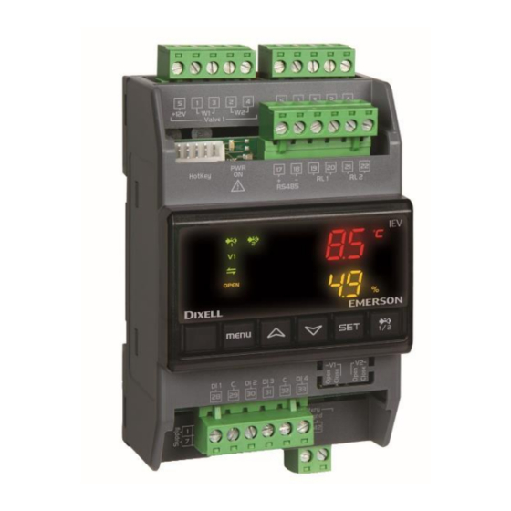
2. Main characteristic IEV is an electronic controller designed for the management of one or two stepper motors (unipolar or bipolar) of electronic expansion valves . IEV is available with a single driver for use with single gas circuit (IEV22D) or double drivers for applications in two gas circuits (IEV24D). -
Page 8: Icons Of The Display
3.1 Icons of the display ON when the displays show a temperature or pressure. °C -°F BAR-PSI ON in parameter programming if the displays show temperature or pressure set points/differentials. ON when the displays show the opening percentage of one of the two valves. ON when the valve is activated for adjustment. -
Page 9: Screen Display
Press the keys to: • scroll through the suction temperature, the evaporation pressure, the superheating value, etc. • scroll through the parameters and increase/decrease the value of the parameters being modified • toggle between the items while browsing the menu menu Press this key to access the menu to view the active alarms. -
Page 10: Viewing The Measured Or Calculated Variables
Other parameters involved on visualization/configuration Ec41 Unit of measure (°C / bar ÷ °F / psi) Ec42 Pressure measurement (0=relative, 1= absolute) Ec45 Operning percentage visualization (0=no, 1=yes) 3.4 Viewing the measured or calculated variables Press the keys to view the values of the following measured and calculated variables concerning valve 1 or 2: Superheating set point (SHC / SHH) Superheating value (SH) - Page 11 1592026260 IEV22-24D GB r.1.0 21.02.2019 11/60...
-
Page 12: Viewing Active Alarms, Alarm Log And The Upload Function
3.5 Viewing active alarms, alarm log and the upload function The following can be viewed by pressing the “menu” key: • ALrM: active alarms (if present); press to view all the other alarms • ALoG: alarm log (last 50 alarms with fifo logic) •... -
Page 13: Modifying The Superheating Set Point
3.7 Modifying the superheating set point Proceed as follows to modify the superheating set point: • press SET for 5 seconds • the superheating set point of valve 1 flashes • press to modify the superheating set point • press SET to confirm the value •... -
Page 14: Viewing Parameters Of Level Pr2
3.9 Viewing Parameters of level Pr2 Proceed as follows to view the parameters: • press SET and simultaneously for 5 seconds • press to view the password Pr2 parameter (last parameter on the list) • press SET • press to enter the value of password Pr2 •... - Page 15 How to modify visibility level To modify the visibility lev of a parameter from Pr1 to Pr2 or from Pr2 to Pr1 is necessary: • enter programming parameters level Pr2 • select the parameter • push SET key and hold it down then press •...
-
Page 16: How To Modify The Parameters
Parameter displayed also in Pr2 3.10 How to modify the parameters Proceed as follows to access the programming area of the parameters displayed in Pr1: • press SET and simultaneously for 5 seconds • press to view the parameter that is to be modified •... -
Page 17: Modifying The Value Of Password Pr2
Modifying the parameters displayed in Pr1: 3.11 Modifying the value of Password Pr2 Proceed as follows to edit the value of the password: • press SET and simultaneously for 5 seconds • press to view the password Pr2 parameter (last parameter on the list) •... - Page 18 1592026260 IEV22-24D GB r.1.0 21.02.2019 18/60...
-
Page 19: Temperature And Pressure Parameter Values
3.12 Temperature and Pressure Parameter Values All parameters that indicate a temperature or pressure can be expressed in degrees Celsius/bar or Fahrenheit/PSI, according to parameter Ec41 that sets the unit of measurement. Modifying the Ec41 parameter from Celsius/bar to Fahrenheit/PSI and vice versa does not involve an automatic update of the parameters from one unit of measurement to the other. - Page 20 Multipolar connector Terminal Type Description AC supply: 24Vac Supply DC supply: Reference “+“ 24 Vdc Analogue input 1 (NTC, PTC, PT1000) Analogue input 2 (NTC, PTC, PT1000) Analogue input 3 (NTC, PTC, PT1000, 0 - 5V, 4 - 20 mA) Analogue input 4 (NTC, PTC, PT1000, 0 - 5V, 4 - 20 mA) LAN + LAN Connection (+ terminal) to connect to IC200 EVO series...
-
Page 21: Digital Inputs
Supercap connector Input from XEC Supercap Ground XEC Supercap HotKey 4K connector This connector is used to connect the HotKey to upload or download the configuration parameters. Valve connector Set the programming of the configuration parameters before connecting the valve; the connection of a valve with features not compatible with the model set in the device can result in a failure of the device or to the valve Do not connect or disconnect the valve while the device is connected to the power;... -
Page 22: Relay
o3 : circuit 1 defrosting - active by an open contact c3 : circuit 1 defrosting - active by a closed contact o4 : call to adjust circuit 2 - active by an open contact c4 : call to adjust circuit 2 - active by a closed contact o5 : circuit 2 cooling/heating function - active by an open contact c5 : circuit 2 cooling/heating function - active by a closed contact o6 : circuit 2 defrosting - active by an open contact... -
Page 23: Kind Of Operation
A high superheating value means that the gas flow passing in the evaporator is insufficient and the evaporation process ends before reaching the end of the evaporator. The valve must be opened to increase the gas flow. A low superheating value means that the gas flow passing in the evaporator is excessive and the evaporation process does not end before reaching the end of the evaporator. - Page 24 7.1.1 Manual mode If manual mode has been selected (par. Et2/Et5), the controller will bring the valve to the number of steps set in parameter Et3/Et6 while remaining in that position; opening and/or closing valve are not active. This can be helpful during the set-up of the machine or in case of maintenance. 7.1.2 Adjustment mode Only at start-up, regardless of the mode of operation, the valve will be completely closed by reaching the maximum number of steps of the Ec13/Ec22 valve plus the extra steps for the complete closure...
- Page 25 during the initial stage, during the Et53 / Et55 time calculated from ▪ when the defrost starts, if the adjustment of the valve requires an aperture value below the step number set under parameter Et52 / Et54, the valve will not close at a value below Et52 / Et54 (which is therefore the minimum aperture threshold in the initial defrost stage).
-
Page 26: Configuration Valve ↔ Circuit
time has elapsed, the adjustment will go ahead as it normally does for defrost. The adjustment request is no longer valid and the digital defrost input and the digital adjustment request input are activated at the same time to perform the defrost. -
Page 27: Valve Management
Chiller heat Valve adjusts in chiller mode pump Winter mode Chiller only Valve does not adjust - Function is disabled Heat pump only Valve adjusts in heat pump mode Chiller heat Valve adjusts in heat pump mode pump Configuration with two valves associated with a circuit Available configurations: valve 1 and valve 2 associated with circuit 1 valve 1 and valve 2 associated with circuit 2... - Page 28 The movement takes place for “HALF A STEP”. Make sure that the technical documentation of the valve you need to use mentions control by half a step, otherwise this will result in an incorrect control of the valve). An impulse is provided on one or two phases in the suitable sequence based on the direction of rotation of the motor (aperture or closure).
- Page 29 Data of pre-configured valves Ec14 / Ec13 / Ec15 / Ec16 / Parameter Ec23 Ec22 Ec50 Ec51/ Model Ec24 Ec25 Ec9/Ec18 (steps (steps*10 /Ec52 Ec53 (mA*10) (mA*10) *10) Manual Config Config. Config. Config. Config. Config. setting Danfoss 2625 ETS-25/50 Danfoss 3530 ETS-100 Danfoss...
- Page 30 Refer to the technical documentation of the valve to set these parameters correctly. Ec50/Ec52 Setting of the movement current (peak or RMS) 0= peak current 1= RMS current (this value is set automatically by the controller if EC9> 0 and / or EC18> 0) Ec51/Ec53 Setting of the microstepping or normal mode adjustment Valve manufacturers use different ways of controlling them;...
-
Page 31: Alarm Management
EXAMPLES OF CONNECTION TO 5-WIRE VALVES UNIPOLAR Due to possible variations in the colour of the wires, before any installation it is recommended to check the technical documentation of the valve to check for any change. Terminal number SPORLAN SAGINOMIYA ORANGE ORANGE YELLOW... -
Page 32: Description Of Parameters
Minimum LOP operating pressure alarm The LOP alarm threshold is expressed as a temperature value and is equal to the pressure of probe 3 and probe 4 converted into a temperature value. The LOP alarm is triggered when the equivalent temperature of the pressure probe drops below Et17/Et37 for the Et47 time. -
Page 33: Parameters To Configure The Relays And Digital Inputs
• Ec41 Unit of measurement selection Used to select the unit of measurement °C / Bar ÷ °F / PSI • Ec42 Type of relative / absolute pressure Used to select whether the pressure detected by the transducers is relative or absolute 8.2 Parameters to configure the relays and digital inputs •... -
Page 34: System Configuration Parameters
• Ec17 / Ec26 = maximum number of steps per second that can be carried out by the valve (value to be calculated based on the technical documentation of the valve) • Ec50 / Ec52 = type of movement or holding current: peak or RMS current. This is an important value for the manual setting of the valve;... - Page 35 If the calculated superheating is below this value and remains below this value for the Et50 time, the regulator carried out corrections on the adjustment (in terms of valve closure) in order to increase the superheating value and go above this threshold again •...
-
Page 36: Other Parameters
• Et48 = MOP alarm signal delay • Et49 = High superheating alarm signal delay • Et50 = Low superheating alarm signal delay • Et51 = PID proportional constant in defrost mode During operation in defrost mode, the valve's adjustment is carried out in accordance with the cooling mode, except for the fact that the value of the PID proportional constant, which is the dedicated Et51 parameter •... -
Page 37: Parameters Table
9. Parameters table Parameter Description Unit Resolution measure IEV driver operation mode Ec 1 0= Stand-alone 1= LAN for Ichill EVO Low pressure probes position Ec 2 0= IEV 1= Ichill 200 EVO Type of valve: Ec 3 0 = Unipolar 1 = Bipolar Valve 1 output operation mode Ec 4... - Page 38 Gas selection Ec 8 0= R22 1= R134a 2= R404a 3= R407c 4= R410a 5= R507c 6= CO2 7= 1234ZE 8= R407F 9= R290 10= R449A 11= R452A 12= R513A 13= R32 14= R450A 15= R454B 16= R454C 17= R452B 18= R1234YF Valve 1 configuration Selection of the bipolar valve body connected...
- Page 39 Number of return steps in opening mode after Ec 12 the valve has been closed completely. These decompress any closing spring inside the valve Full steps or to prevent sealing the circuit. For unipolar valves refer to the notes included in paragraph 7.3.
- Page 40 Number of additional steps to achieve Ec 20 complete closure. When a closing request is received, the valve starts from the current number of steps and moves to 0, then closes 8000 Full steps for the set number of steps. For unipolar valves refer to the notes included in paragraph 7.3.
- Page 41 Pb3 and Pb4 configuration (Pb3 used for valve Ec 28 1 and Pb4 used for valve 2) 0 = temperature (NTC probe) 1 = temperature (PTC probe) 2 = temperature (PT1000 probe) 3 = pressure (4÷20mA signal) 4 = pressure (0÷5V signal) Pressure value at 4mA / 0,5V Ec30 Ec 29...
- Page 42 Relay 2 configuration (o1= active when the Ec 36 contact is open; c1= when active the contact is closed) 0= not used 1= active in case of circuit 1 probe error 2= active in case of MOP, LOP and circuit 1 probe error 3= active in case of high superheating, low superheating, and circuit 1 probe error...
- Page 43 Digital input 3 configuration (o1= active when Ec 39 the contact is open; c1= when active the contact is closed) 0= not used 1= circuit 1 valve activation 2= circuit 1 valve operation mode (cooling or heating) 3= circuit 1 defrost mode 4= circuit 2 valve activation 5= circuit 2 valve operation mode (cooling or heating)
- Page 44 LAN address (used only if connected to the Ec 47 IC200 EVO) Map code (only reading) 9999 Ec 48 Firmware release (only reading) Ec 49 Type of current valve 1: peak or RMS Ec 50 0= peak 1= RMS (this value is set automatically by the controller if EC9>...
- Page 45 Absolute number of steps the valve has to Et 6 Ec23 Ec22 Full steps move in manual mode PID configuration in chiller mode (valve 1 and valve 2) PID proportional constant in chiller mode 50.0 °C Et 7 °F PID integral time in chiller mode Et 8 PID derivative constant in chiller mode Et 9...
- Page 46 Holding time of Et1 steps at the start-up of the Et 23 regulation in chiller mode Interval of updating valve position in chiller Et 24 mode Interval time for valve opening when a probe is Et 25 damaged in chiller mode Valve opening percentage when a probe is Et 26 damaged in chiller mode...
- Page 47 Holding time of Et4 steps at the start-up of the Et 43 regulation in heat pump Interval of updating the valve output in heat Et 44 pump mode Interval time for valve opening when a probe is Et 45 damaged in heat pump mode Valve opening percentage when a probe is Et 46 damaged in heat pump mode...
-
Page 48: Alarm Codes And Actions
10. Alarm codes and actions Code Meaning Cause of alarm Action taken Type of reset displayed Alarm of probe Faulty probe or Blocked adjustment by the valve Automatic when PB1, Pb2, Pb3 value out of closing; connection or Pb4 range Active alarm relay output if enabled problems are by parameter;... - Page 49 Minimum Evaporation Automatic action of the controller to Automatic. operating pressure < LOP counteract the LoP; The condition to pressure activation Active alarm relay output if enabled come out from threshold by parameter; minimum delayed by Et39 Enable the buzzer; operating seconds icon flashes;...
-
Page 50: Parameter Programming Key - Hotkey 4K
ALAn No serial Problem related Blocked adjustment by the valve Automatic on communication to serial closing; the fault being with Ichill communication Active alarm relay output if enabled resolved: with Ichill by parameter; • LAN Enable the buzzer; connection icon flashes; polarity Code of alarm on the display. -
Page 51: Download
11.1 DownLoad The download occurs automatically if: • the HotKey 4K is inserted into the connector 5-way while the device is not powered • the instrument is powered • the download started If the device detects the presence of the programming key (connected to the serial port), a key recognition process is launched that involves verification of compatibility of the data and then the data loading process from the key is launched and the data are saved in the internal memory. -
Page 52: Serial Output
12. Serial output The IEV valve driver has an RS485 or TTL serial output (only 1 of the 2 outputs can be used) for the following possible uses: • connection to a Personal computer: the configuration parameters of the driver can be programmed via Wizmate Prog Tool kit •... -
Page 53: Installation
14. Installation The devices should not be installed in areas where there are the following situations: • use the controller only within the operating limits, avoiding sudden temperature changes with high atmospheric humidity (to prevent formation of condenses) • High mechanical stress (vibration and / or impact) •... -
Page 54: Analogue Input Connection
14.2 Analogue input connection 14.2.1 Temperature probes (NTC and PTC) 2-row sensors that do not require polarity to be respected. Each sensor must be connected through one of the inputs (from Pb1 to Pb10) and the common (PbC) as shown in the diagram below. Recommendations: - follow the diagram of the device used, for the numbering. -
Page 55: Supercap Connection Diagram
Recommendations: - follow the diagram of the device used, for the numbering. - the configuration is determined by the application. 14.2.3 Pressure transducers and ratiometric pressure transducers (0 - 5V) 3-row sensors that require +5Vdc power supply. 14.2.4 Digital input connection 14.3 Supercap connection diagram XEC supercap module supplies the energy to close the valve in case of power down. - Page 56 XEC supercap doesn’t supply the IEV in normal working conditions, but supplies needed energy to close the valve in case of power down. Connection with IEV22D (one valve) Connection with IEV24D (two valves) 1592026260 IEV22-24D GB r.1.0 21.02.2019 56/60...
-
Page 57: Lan Connection
14.4 LAN CONNECTION IEV22D or IEV24D can be connected to an IC200 EVO series (IC206CX EVO, IC208CX EVO, IC205D EVO, IC207D EVO). Evaporating temperature probe has to be connected to the IEV and suction pressure transducer can be connected to the IEV or to the Ichill (by configuring dedicated parameters). To guarantee the best regulation is recommended to connect the suction pressure transducer directly to the IEV. -
Page 58: Plastic Container
15. PLASTIC CONTAINER The controllers are fitted on a DIN rail (EN 50022, DIN 43880). Assembly: On a DIN rail (EN 50022, DIN 43880) Fastened with screws via the removable plastic flaps. Material: PC-ABS Thermoplastic Self-extinguishing: V0 (UL94) Comparative Tracking Index 300V (CTI):... -
Page 59: Analogue Inputs
16.2 Analogue inputs Number of inputs: Type of analogue input: NTC (-50T110°C; 10KΩ at 25°C) / (-58T230°F;10KΩ (configurable software at 25°C) parameter) PTC (-55T150°C; 990Ω at 25°C) / (-58T302°F; 990Ω at 25°C) PT1000 (-50T100°C ; 1K Ω at 0°C) / (-58T212°F; 1KΩ at 0°C) Rathiometric: 0 to 5V (input resistance 3.7KΩ) Current: 4 to 20 mA (input resistance 100Ω) -
Page 60: Operating Conditions
16.5 Operating conditions Operating temperature: -10°C ÷ 55°C Storage temperature: -30°C ÷ 85°C Relative humidity: 20% ÷ 85% Degree of protection IP 1592026260 IEV22-24D GB r.1.0 21.02.2019 60/60...
Need help?
Do you have a question about the Dixell IEV22D and is the answer not in the manual?
Questions and answers