
Subscribe to Our Youtube Channel
Related Manuals for Planet LRP-104CET


Summary of Contents for Planet LRP-104CET
- Page 1 Industrial 1-Port Coax/UTP Long Reach PoE+ 4-Port 10/100TX PoE Extender LRP-104CET User’s Manual...
-
Page 2: Table Of Contents
1. Package Contents ................. 3 2. Application Diagram ................4 2.1 Point to Multi-point ................ 4 2.1.1 LRP-101CH to LRP-104CET ............ 4 2.1.2 LRP-101UH to LRP-104CET ........... 5 2.2 Multi-Point to Multi-Point ..............6 2.2.1 LRP-822CS/LRP-1622CS to LRP-104CET ......... 6 3. -
Page 3: Package Contents
1. Package Contents Thank you for purchasing PLANET Industrial 1-Port Long Reach PoE+ 4-Port 10/100TX PoE Extender, LRP-104CET. In the following section, the term “LRP Extender” means the LRP-104CET. Open the box of the LRP Extender and carefully unpack it. The box should... -
Page 4: Application Diagram
Ethernet. The solution works in pairs for point to point and point to multipoint connectivity. The LRP-104CET supports two ways as power source to inject 802.3af/at PoE to remote standard PDs (Powered Devices). z Remote LRP Power from LRP Injector/switch over coaxial cable z Local DC power from power supply through LRP-104CET’s terminal... -
Page 5: Lrp-101Uh To Lrp-104Cet
Ethernet Switch 802.3af/802.3at PoE LRP-101CH Long Reach PoE Injector PoE In-use LRP-104CET PoE IP Camera PoE Power Budget 120 watts (max.) 2.1.2 LRP-101UH to LRP-104CET Remote LRP Power over UTP 110-240V AC LRP-104CET Long Reach PoE Extender Ext. Fault Power Usage... -
Page 6: Multi-Point To Multi-Point
2.2 Multi-Point to Multi-Point Remote power LRP Power through BNC with DC 56V input or Local Power with External DC input (DC 24V~48V) 2.2.1 LRP-822CS/LRP-1622CS to LRP-104CET Remote LRP Power Power over Coaxial 802.3at PoE+ LRP-104CET LRP-822CS IP Camera Long Reach PoE Extender Ext. -
Page 7: Hardware Introduction
3. Hardware Introduction 3.1 Physical Dimensions LRP-104CET LRP Extender dimensions (W x D x H): 135 x 87.8 x 56mm Rear View Top View Mounting Kit Mounting Kit Side View DIN-Rail Kit Front View Side View Ext. Fault Power... -
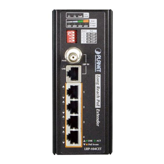
Page 8: Front Panel
10W 20W 30W 40W Port LRP IN PoE In-use LRP-104CET Figure 3-2: LRP-104CET Front Panel 3.3 The Upper Panel The upper panel of the LRP Extender consists of one terminal block connector within two DC power inputs. 1 2 3 4 5 6... -
Page 9: Led Indicators
3.4 LED Indicators External Power Supply Color Function Green Lights to indicate power 1 has power. Green Lights to indicate power 2 has power. Lights to indicate either power 1 or power 2 has no FAULT power. PoE Usage Color Function Green Lights to indicate the power usage is ≥ 10W. -
Page 10: Poe Dip Switch Indication
3.5 PoE DIP Switch Indication The LRP Extender provides an adjustable switch that can be used to control the operation of the PoE output. Port ON (default) Port-1 PoE Enable Port 1 Port-1 PoE Disable ON (default) Port-2 PoE Enable Port 2 Port-2 PoE Disable ON (default) -
Page 11: Hardware Specifications
4. Hardware Specifications Model LRP-104CET Hardware Specifications Four 10/100BASE-TX RJ45 auto-MDI/ Copper Ports MDI-X Four ports with 802.3at/af PoE injector PoE Injector Ports function with Port-1 to Port-4 Four DIP switches to control PoE output Functionality on or off with Port-1 to Port-4 PoE Standards IEEE 802.3at Power over Ethernet Plus/... - Page 12 Coaxial cable: 75 Cat. 3, 4, 5, 5e UTP cable (100 meters, RG-6/U cable, less max.) Cabling than12Ω/1000 ft EIA/TIA-568 RG-59/U cable, less 100-ohm STP (100 than 30Ω/1000 ft. meters, max.) Max. 200m with Max. 100m with PoE+ output (656ft.) PoE+ output Max. 400m (328ft.) with PoE output Max.
- Page 13 Green: DC Power 1 3 x LED for External Green: DC Power 2 power supply: Red: Power Fault 4 x LED for PoE Green: 10W/20W/30W/40W Usage: LED Indicator Green: PWR 2 x LED for Long Reach PoE In: Green: LNK 2 x LED for each Green: 10/100Mbps LNK/ACT RJ45 interface...
- Page 14 Environment Operating: -20~70 degrees C Temperature Storage: -20~70 degrees C Operating: 5~95% (non-condensing) Humidity Storage: 5~95% (non-condensing) Performance 802.3af/at PoE Total Output Capability Remote Remote LRP Local DC Data LRP power power by power Distance rate(Upload/ through LRP-822CS/ through Download) LRP-1622CS terminal W/56VDC...
-
Page 15: Installation Precautions
Note 5.2. Installation Precautions of Remote Power by UTP Cable When installing LRP PoE over UTP injector, it only can work with PLANET LRP Extender, the LRP-104CET or LRP-101UE. Please confirm that other non-PoE equipment is not connected with the UTP cable. If connected with standard... -
Page 16: Installation Precautions Of Local Power
5.3 Installation Precautions of Local Power Installation of LRP injector or LRP switch. If you need to increase the PoE power budget of the LRP-104CET, you must use an external DC power supply. The 6-contact terminal block connector on the upper panel of LRP Extender is used for two DC redundant power inputs. -
Page 17: Wiring The Fault Alarm Contact
1. The wire gauge for the terminal block should be in the range between 12 and 24 AWG. 2. The DC power input range is 24V ~ 48V DC. Note 5.4 Wiring the Fault Alarm Contact The fault alarm contacts are in the middle of the terminal block connector as the picture shows below. -
Page 18: Installation
RJ45 ports to avoid the LRP-104CET to malfunction. 6.1 Applications of LRP-101CH or LRP Switch with coaxial cable Type 1 One LRP-101CH with PoE power input and one LRP-104CET with PoE power output The LRP Injector is powered via IEEE 802.3at/af PoE. An IEEE 802.3at/af compliant PoE PD will automatically be powered by the LRP Extender via UTP. -
Page 19: Installation Instructions
PWR LED of LRP-101CH and LRP-104CET should be lit up immediately. Step 3. Connect Cat5/6 UTP cable to LRP-104CET and IEEE 802.3at/af complied PoE IP camera or PoE Wireless AP. The LRP-101CH accepts IEEE 802.3at equipment for optimal power injection. - Page 20 Step 2. Connect Cat5/6 UTP cable to LRP-101CH and non-PoE switch or workstation. Step 3. Connect 48~56V DC power adapter to LRP-101CH power socket, then the PWR LED of LRP-101CH and LRP-104CET should be lit up immediately. Step 4. Connect Cat5/6 UTP cable to LRP-104CET and IEEE 802.3at/af complied PoE IP camera or PoE Wireless AP.
-
Page 21: Applications Of Lrp-101U-Kit With Utp/Twisted-Pair Cable
LRP-1622CS) can be downloaded from the PLANET website or contact the PLANET support team. Note 6.2 Applications of LRP-101U-KIT with UTP/Twisted-pair Cable Type 1 LRP-101UH with PoE power input and LRP-104CET with PoE power output Remote LRP Power over UTP LRP-104CET Long Reach PoE Extender Ext. - Page 22 PWR LED of LRP-101UH and LRP-104CET should be lit up accordingly. Step 4. Connect Cat5/6 UTP cable to LRP-104CET and IEEE 802.3at/af complied PoE IP camera or PoE Wireless AP. The LRP-101UH accepts IEEE 802.3at equipment for optimal power injection.
- Page 23 Step 3. Connect Cat5/6 UTP cable to LRP-101UH and non-PoE switch or workstation. Step 4. Connect 48~56V DC power adapter to LRP-101UH power socket, and then the PWR LED of LRP-101UH and LRP-104CET should be lit up immediately. Step 5. Connect Cat5/6 UTP cable to LRP-104CET and IEEE 802.3at/af...
-
Page 24: Applications Of Lrp Injector Or Lrp Switch Powered By External Dc Power Supply
6.3 Applications of LRP Injector or LRP Switch powered by External DC power supply The LRP-104CET can be powered via External DC 24~48V input. You can refer to Section 5.3 for Installation Precautions of Local Power. This section describes its applications and precautions. -
Page 25: Power Input
After the power over coaxial injector is enabled, the center pin of the coaxial cable has electricity. Please do not touch the center pin. Warning Type 2 One LRP-822CS/LRP-1622CS and one LRP-104CET with PoE power output Local Power Power over Coaxial 802.3at PoE+... - Page 26 After the power over coaxial injector is enabled, the center pin of the coaxial cable has electricity. Please do not touch the center pin. Warning Type 3 LRP-101UH and LRP-104CET with PoE power output Local Power LRP-104CET Long Reach PoE Extender Ext.
-
Page 27: Appendix A: Networking Connection
Appendix A: Networking Connection A.1 Switch’s RJ45 Pin Assignments 10/100Mbps, 10/100BASE-TX RJ45 Connector pin assignment MDI-X Contact Media Dependent Media Dependent Interface Interface-Cross Tx + (transmit) Rx + (receive) Positive (VCC+) Tx - (transmit) Rx - (receive) Positive (VCC+) Rx + (receive) Tx + (transmit) Negative (VCC-) 4, 5... - Page 28 There are 8 wires on a standard UTP/STP cable and each wire is color-coded. The following shows the pin allocation and color of straight cable and crossover cable connection: Straight Cable SIDE 1 SIDE 2 1 = White/Orange 1 = White/Orange SIDE 1 1 2 3 4 5 6 7 8 2 = Orange...
Need help?
Do you have a question about the LRP-104CET and is the answer not in the manual?
Questions and answers