
Related Manuals for Advantech IDK-1121WP Series


Summary of Contents for Advantech IDK-1121WP Series
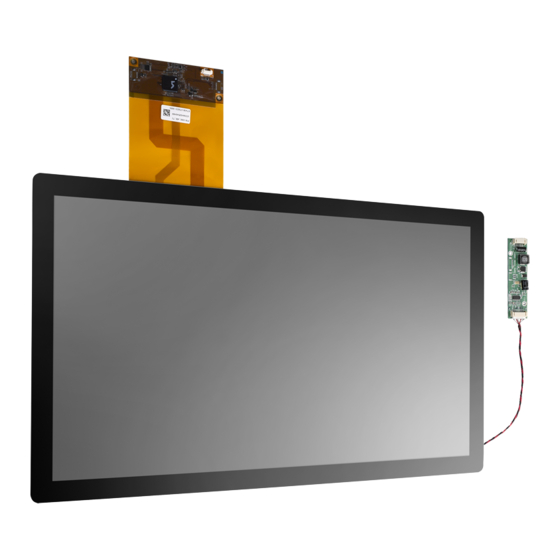
- Page 1 User Manual IDK-1121WP Series 21.5" FHD Industrial Display Kit with Touch Solution...
- Page 2 No part of this manual may be reproduced, copied, translated or transmitted in any form or by any means without the prior written permission of Advantech Co., Ltd. Information provided in this manual is intended to be accurate and reliable. How- ever, Advantech Co., Ltd.
- Page 3 Because of Advantech’s high quality-control standards and rigorous testing, most of our customers never need to use our repair service. If an Advantech product is defec- tive, it will be repaired or replaced at no charge during the warranty period. For out- of-warranty repairs, you will be billed according to the cost of replacement materials, service time and freight.
- Page 4 IDK-1121WP User Manual...
-
Page 5: Table Of Contents
Contents Chapter Overview..........1 General Description .................. 2 Specifications .................... 2 1.2.1 LCD Panel..................2 1.2.2 Touch Screen................2 1.2.3 Environment.................. 3 LCD Functional Block Diagram ..............3 Figure 1.1 Function block diagram ..........3 Mechanical Characteristics ............... 3 Touch Screen driver.................. 4 Absolute Maximum Ratings .............. - Page 6 Appendix B Handling Precautions ....... 27 Handling Precautions................28 IDK-1121WP User Manual...
-
Page 7: Chapter 1 Overview
Chapter Overview... -
Page 8: General Description
General Description The Advantech IDK-1121WP series comes with a 21.5" industrial grade IPS LCD dis- play with Projected Capacitive touch. IDK-1121WP series supports Projected Capac- itive touch with low power consumption. IDK-1121WP series is ideal for embedded applications needing maximum flexibility for mechanical design. -
Page 9: Environment
1.2.3 Environment Operating Temperature: 0 ~ 50 °C Storage Temperature: -20 ~ 60 °C LCD Functional Block Diagram The following diagram shows the functional block of the 21.5 inch Color TFT-LCD Module: Figure 1.1 Function block diagram Mechanical Characteristics Front View IDK-1121WP User Manual... -
Page 10: Touch Screen Driver
Rear View LED Driver Board Touch Screen driver Please down load the touchscreen driver from the Advantech website. IDK-1121WP User Manual... -
Page 11: Absolute Maximum Ratings
Absolute Maximum Ratings The following are maximum values which, if exceeded, may cause faulty operation or damage to the unit. 1.6.1 TFT LCD Module Item Symbol Min. Max. Unit Note Logic/LCD Drive Voltage -0.3 [Volt] °C 1.6.2 Absolute Environment Ratings Item Symbol Min. - Page 12 IDK-1121WP User Manual...
-
Page 13: Chapter 2 Electrical Characteristics
Chapter Electrical Characteristics... -
Page 14: Tft Lcd Module
TFT LCD Module Requires two power inputs, one is employed to power the LCD electronics and to drive the TFT array and liquid crystal. The second power input is for the LED/Back- light, typically generated by a LED Driver. The LED Driver is an external unit to the LCDs. -
Page 15: Backlight Unit (Led Driver)
Power consumption (VLCD =5V, 25°C, fV (frame frequency=60Hz condition) Backlight Unit (LED Driver) The following characteristics are measured under stable conditions at 25°C: Table 2.2: Backlight driving conditions Values Item Symbol Unit Condition Min. Typ. Max. Input Voltage [Volt] Input Current 0.24 PWM Dimming Frequency... -
Page 16: Interface Connections
Interface Connections 2.3.1 LCD Module LCD Connector (CN1) : IS100-L30O-C23 (UJU) , GT103-30S-HF15 (LSM), GT103-30S-HF15-M (LSM) Mating Connector : FI-X30C2L (Manufactured by JAE) or Equivalent Table 2.3: MODULE CONNECTOR(CN1) PIN CONFIGURATION No Symbol Description No Symbol Symbol FR0M Minus signal of odd channel SR1P Plus signal of even channel 1... - Page 17 LVDS Input characteristics DC Specification Description Symbol Unit Notes LVDS differential voltage LVDS common mode voltage LVDS input voltage range Change in common mode voltage Note! Does not have any noise & peaking in LVDS signal. AC Specification Description Symbol Unit Notes LVDS Clock to Data Skew...
- Page 18 IDK-1121WP User Manual...
-
Page 19: Chapter 3 Signal Characteristics
Chapter Signal Characteristics... -
Page 20: Pixel Format Image
Pixel Format Image Following figure shows the relationship between input signal and LCD pixel format. The Input Data Format LVDS 2 Port IDK-1121WP User Manual... -
Page 21: Signal Timing Specifications
Signal Timing Specifications This is the signal timing required at the input of the TMDS transmitter. All of the inter- face signal timing should be satisfied with the following specifications for it's proper operation. Table 3.1: TIMING TABLE ITEM Symbol Unit Note Period... -
Page 22: Signal Timing Waveforms
Signal Timing Waveforms Color Input Data Reference The brightness of each primary color (red,green,blue) is based on the 8-bit gray scale data input for the color; the higher the binary input, the brighter the color. The table below provides a reference for color versus data input. IDK-1121WP User Manual... -
Page 23: Power Sequence
Power Sequence IDK-1121WP User Manual... -
Page 24: Vlcd Power Dip Condition
POWER SEQUENCE Note1! The above power sequence should be satisfied at these case – AC/DC Power On/Off – Mode change ( resolution, frequency, timing, sleep mode, color depth change, etc. ) If not to follow power sequence, there is a risk of abnormal display. Please avoid floating state of interface signal at invalid period. -
Page 25: Chapter 4 Touchscreen & Touch Controller
Chapter Touchscreen & Touch Controller... -
Page 26: Touch Characteristics
Touch Characteristics Advantech’s IDK-1121WP series projective capacitive touch screen adopts a COF (Chip on FPC) design so an extra touch control board is not required. This communi- cates with a PC system directly through USB connectors. The superior design is sen- sitive, accurate, and user friendly. -
Page 27: Pin Assignment And Description
Pin Assignment and Description 4.5.1 USB interface connector and pin assignment The USB interface connector is a 5-pin and pitch 1.25mm connector. The pins are numbered as shown in the table below. Pin No. Symbol Remark IDK-1121WP User Manual... - Page 28 IDK-1121WP User Manual...
-
Page 29: Appendix Alcd Optical Characteristics
Appendix LCD Optical Characteristics... -
Page 30: Lcd Module Optical Characteristics
LCD Module Optical Characteristics The optical characteristics are measured under stable conditions at 25°C (Room Temperature): Table A.1: Optical Characteristics Item Conditions Min. Typ. Max. Unit Note Horizontal 85/85 89/89 CR = 10 Viewing Angle [degree] Vertical 85/85 89/89 CR = 10 Luminance 2, 3 Uniformity... - Page 31 Note 2 9 points position Note 3 9-point luminance uniformity is defined by dividing the maximum luminance values by the minimum test point luminance Minimum [L (1) ~ L (9)] Maximum [L (1) ~ L (9)] Note 4 Measurement method The LCD module should be stabilized at given temperature for 20 minutes to avoid abrupt temperature change during measuring.
- Page 32 IDK-1121WP User Manual...
- Page 33 Appendix Handling Precautions...
- Page 34 Handling Precautions The optical characteristics are measured under stable conditions at 25°C (Room Temperature) Since the front polarizer is easily damaged, be very careful not to scratch it. Be sure to turn off the power supply when inserting or disconnecting from the input connector.
- Page 35 No part of this publication may be reproduced in any form or by any means, electronic, photocopying, recording or otherwise, without prior written permis- sion of the publisher. All brand and product names are trademarks or registered trademarks of their respective companies. © Advantech Co., Ltd. 2018...
Need help?
Do you have a question about the IDK-1121WP Series and is the answer not in the manual?
Questions and answers