Table of Contents
Advertisement
Quick Links
Download this manual
See also:
Hardware Manual
Advertisement
Table of Contents

Subscribe to Our Youtube Channel
Related Manuals for YASKAWA MP2600iec


Summary of Contents for YASKAWA MP2600iec
- Page 1 MP2600iec Hardware Manual...
-
Page 3: Table Of Contents
1 Introduction 1.1 MP2600iec Features - - - - - - - - - - - - - - - - - - - - - - - - 3 1.2 MP2600iec Appearance- - - - - - - - - - - - - - - - - - - - - - 4 1.4 Dimensions- - - - - - - - - - - - - - - - - - - - - - - - - - - - - - - 5... - Page 4 9 Ethernet 9.1 Connectivity Information- - - - - - - - - - - - - - - - - - - - - 25 9.2 Ethernet Connector Details- - - - - - - - - - - - - - - - - - - 25 9.3 Ethernet Cable - - - - - - - - - - - - - - - - - - - - - - - - - - - 26 9.4 Ethernet Connection Examples- - - - - - - - - - - - - - - - 26 10 Cable Diagrams...
-
Page 5: Introduction
1.1 MP2600iec Features 1 Introduction 1.1 MP2600iec Features MP2600iec is a single-axis machine controller option card that is attached to a Sigma-5 servo amplifier. The servo amplifier and controller are factory assembled, providing a compact, all-in-one servo/controller package with the following features: ... -
Page 6: Mp2600Iec Appearance
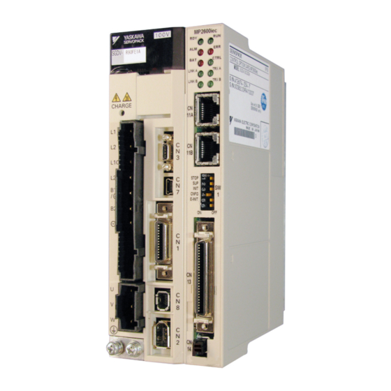
1.2 MP2600iec Appearance 1.2 MP2600iec Appearance The following figure shows the external appearance of the MP2600iec controller (Note: The servo amplifier is not shown). LED (10 points) Ethernet Port A Ethernet Port B DIP Switch (6 points) CN13 Port Analog I/O, Digital I/O External Encoder (incremental) 3.6V Lithium Battery... -
Page 7: Dimensions
1.3 Dimensions 1.3.1 MP2600iec Controller 1.3 Dimensions 1.3.1 MP2600iec Controller (20) Dimensions in mm. - Page 8 1.3 Dimensions 1.3.1 MP2600iec Controller...
-
Page 9: Specifications
2.1 General Specifications 2 Specifications 2.1 General Specifications Item Specifications Ambient Operating 0 to 55°C Temperature Ambient Storage -20°C to +85°C Temperature Ambient Operating 90% RH or less (with no condensation) Humidity Ambient Storage 90% RH or less (with no condensation) Environmental Humidity Conditions... -
Page 10: Mp2600Iec Hardware Specifications
2.2 MP2600iec Hardware Specifications 2.2 MP2600iec Hardware Specifications Item Specification 200 MHz, 32 bit, ARM 9 SDRAM 32 MB Memory SRAM 512 kB with battery backup Flash 4 MB flash. Code and parameter storage. 10 LEDs (red and green - operating mode,... -
Page 11: Ordering Reference
3 Ordering Reference 3.1 Component Model Numbers SGDV R70 A E 1 A 000 00 0 300 Series SGDV SERVOPACK Option Module Code Specifications Current MP2600iec 1.5 Axis Applicable Servomotor Machine Controller Voltage Code Module Max. Capacity kW 0.05 Options (parameter) -
Page 12: Additional Model Numbers
Type Model Part Number Note Battery JZSP-BA01 Replacement Battery Holder Kit SGDV-OZC02A Replacement (does not include battery) CN13 (MP2600iec) Terminal Block CBK-U-MP2Bxx Conversion Kit xx denotes cable length (m) CN13 (MP2600iec) A5 = 0.5 CFC-U-MP2Bxx (Flying Leads) 01 = 1... -
Page 13: Mounting
4.1 Mounting Information 4 Mounting 4.1 Mounting Information The MP2600iec controller is pre-assembled to the Sigma-5 servo amplifier by the factory. Do not disassemble the unit in the field. -
Page 14: Installation Standards
4.2 Installation Standards 4.2 Installation Standards The SERVOPACK must be installed in a fully enclosed metal control panel. Observe the standards for mounting SERVOPACKs in control panels, including those for the mounting SERVOPACKs side by side in one control panel as shown in the following illustration. •... -
Page 15: Inputs/Outputs
5.1 CN13 Connection Diagram 5 Inputs/Outputs 5.1 CN13 Connection Diagram CN13 External Device Analog -15V Output AO_GND -10 +10V External Device -15V Analog AI_GND Input -10 +10V Pulse Encoder Generator Interface PILC(24V) PILC(12V) Connect to pin 10, 34, or 9 based on signal level PILC(5V) Z-phase Latch Input... -
Page 16: Cn13 Connection Description
5.2 CN13 Connection Description 5.2 CN13 Connection Description Alphabetical Numerical CN 13 Pin Code Description Description Code CN 13 Pin Analog Output Analog Input Analog Input Analog Input Ground AI_GND no connection Analog Output Encoder A phase + Analog Output Ground AO_GND Encoder A phase - Digital Input 0... -
Page 17: External Encoder Interface
5.3 External Encoder Interface 5.3 External Encoder Interface Item Specification Number of One channel (Phase A, Phase B, Index pulse, or SSI clock) channels Phase A & B: 5V differential input (RS-422 compatible), non- insulated. Maximum frequency 4MHz. Input circuit Index pulse: 5V/12V/24V photo coupler input. -
Page 18: On-Board Digital I/O
5.4 On-Board Digital I/O 5.4.1 Inputs 5.4 On-Board Digital I/O 5.4.1 Inputs • 8 general purpose • Optically isolated • 24 V @ 5 mA • Entire bank is configurable as either current sinking or sourcing via connection of common Digital Input Circuit To configure all controller inputs as sinking, wire +24VDC to pins 13 and 38. - Page 19 5.4 On-Board Digital I/O 5.4.2 Outputs 5.4.2 Outputs • 8 general purpose • Optically isolated • 24 V @ 50 mA • Current source or sink (connection to both emitter and collector are provided) Digital Output Circuit Connection Examples of Output Circuits •...
-
Page 20: Sigma-5 I/O
5.5 Sigma-5 I/O 5.4.2 Outputs 5.5 Sigma-5 I/O The Sigma-5 includes seven digital inputs and three digital outputs that can be monitored & controlled by the MP2600iec. Photocoupler output Max. operating voltage: 30 VDC Max. operating current: 50 mA DC SGDV SERVOPACK 3.3kΩ... -
Page 21: Analog I/O
5.6 Analog I/O 5.6.1 Analog Input 5.6 Analog I/O 5.6.1 Analog Input Item Specification Analog input range -10V ~ +10V Number of input channels Electrical isolation None Absolute maximum input ± 15V Input Impedance 20k Resolution 16 bit 25°C ±0.1% (± 10mV) Accuracy 0 ~ 55°C ±0.3% (±... - Page 22 5.6 Analog I/O 5.6.2 Analog Output 5.6.2 Analog Output Item Specification Analog output range -10V ~ +10V Number of output channels Electrical isolation None Maximum load current ± 5mA Resolution 16 bit 25°C ±0.3% (± 30mV) Accuracy 0 ~ 55°C ±0.3% (±...
-
Page 23: Dip Switches
6.1 Switch Settings 6 DIP Switches 6.1 Switch Settings STOP CNFG EINIT DHCP Switch Name Setting Operating Mode Default Details User program stopped STOP Stops the user program execution. User program running Firmware Load If set to ON, the controller boots up in the mode that can upgrade the firmare. - Page 24 6.1 Switch Settings...
-
Page 25: Led Outputs
7 LED Outputs The following table shows the indicators that show the operating status of the controller and error information. Indicator Color Status Green Lit during normal operation. Green Lit during execution of user program. Lit when warning occurs. Lit when malfunction occurs. Lit when option card is communicating to the Green CTRL... -
Page 27: Battery
8.1 Battery Installation 8 Battery 8.1 Battery Installation A 3.6V lithium battery must be used to retain SRAM data in the controller when the power is off. SRAM will last for one hour without the battery connected. The battery power can be applied through the battery connector (CN14), or through the I/O connector (CN13 pins 7[+] &... - Page 28 8.1 Battery Installation Battery Holder Installation Instructions: Remove the plastic case from the controller by pressing the tabs at the top and bottom. Insert the tab of the metal plate into the last vent slot on the bottom front of the case as shown. Line up the hole in battery holder with the hole in the metal plate and secure the battery holder with the...
-
Page 29: Ethernet
9.1 Connectivity Information 9 Ethernet 9.1 Connectivity Information The MP2600iec supports 100MB speeds exclusively. Two separate networks are possible using both CN11A and CN11B. A default gateway can be specified only for the network attached to CN11A. 9.2 Ethernet Connector Details Ethernet Connector Specification and Pin Array The following table provides the Ethernet connector specifications. -
Page 30: Ethernet Cable
Up to 100m 100Base-TX 100Base-TX Ethernet Switch Ethernet Switch Up to 100m Up to 100m Up to 100m * Note: The MP2600iec can only be plugged into Station* Station* a 100Base-TX Ethernet port. Specification When Connecting to a Item Ethernet Switch... - Page 31 9.4 Ethernet Connection Examples Connection Example 2 SGDV with MP2600iec 100 Base-TX (up to 100m) Note: The MP2600iec can only be plugged into a 100Base-TX Ethernet port. Caution High frequency wave noise from other devices in the installation environment may cause errors in communications.
- Page 32 9.4 Ethernet Connection Examples Connection Example 3 SGDV with MP2600iec Station* * Note: The MP2600iec can only be plugged into a 100Base-TX Ethernet port Core 100Base-TX Core 100Base-TX Ethernet Switch Servomotor MotionWorks IEC...
-
Page 33: Cable Diagrams
10.1 CBK-U-MP2B-xx 10 Cable Diagrams 10.1 CBK-U-MP2B-xx Terminal Block - Controller... -
Page 34: Cfc-U-Mp2B-Xx (Flying Lead-Controller)
10.2 CFC-U-MP2B-xx 10.2 CFC-U-MP2B-xx Flying Lead - Controller Dimensions in mm Model X =Cable Length CFC-U-MP2B-A5 500 mm CFC-U-MP2B-01 1000 mm CFC-U-MP2B-03 3000 mm... -
Page 35: Sbk-U-Vba-Xx (Terminal Block-Servo Amp)
10.3 SBK-U-VBA-xx 10.3 SBK-U-VBA-xx Terminal Block - Servo Amplifier... - Page 36 10.4 JZSP-CSI02-x-E 10.4 JZSP-CSI02-x-E Flying Lead - Servo Amplifier SERVOPACK End Connector 10126 - 6000 EL ( by Sumitomo 3 M Ltd. ) 10326 - 52 A 0 - 008 Shell Cable ( Ivory ) SSRFPVV-SB AWG# 28 13 P ×...
-
Page 37: Cable Shielding, Segregation & Noise Immunity
11 Cable Shielding, Segregation & Noise Immunity Proper SMC 3010 Shields tied Terminal Block back at device Connector Case PROPER Shield connected across terminal block. Shields tied Terminal Block back at device Connector Case PROPER PROPER Shield tied back at Shields of field terminal block. - Page 39 12 Firmware Upgrade It is possible to upgrade the Controller firmware in the field. For detailed instructions, please refer to Product Note PN.MCD.03.083: Upgrading the MP2 iec Controller Firmware. This document may be downloaded from our website, www.yaskawa.com.
- Page 42 Yaskawa . . . A World of Automation Solutions Yaskawa Electric America, Inc. Yaskawa Electric Europe Yaskawa Electric Corporation Chicago-Corporate Headquarters Hauptstrasse 185, 65760 New Pier Takeshiba 2121 Norman Drive South Eschborn, Germany South Tower, 1-16-1 Kaigan Waukegan, Illinois 60085...
Need help?
Do you have a question about the MP2600iec and is the answer not in the manual?
Questions and answers