Table of Contents
Advertisement
Quick Links
Advertisement
Table of Contents

Subscribe to Our Youtube Channel
Related Manuals for AIC Virgo


Summary of Contents for AIC Virgo
- Page 1 Virgo Server Motherboard User's Manual UM_Virgo_v3.1_102218...
-
Page 2: Table Of Contents
Table of Contents Preface ������������������������������������������������������������������������������������������������� i Safety Instructions ������������������������������������������������������������������������������ ii About This Manual ������������������������������������������������������������������������������ iii Chapter 1� Product Features �������������������������������������������������������������� 1 1�1 Componenets �����������������������������������������������������������������������������������1 1.2 Specifications �����������������������������������������������������������������������������������2 1�3 Feature ���������������������������������������������������������������������������������������������3 Chapter 2� Hardware Setup ���������������������������������������������������������������� 4 2�1 Central Processiong Unit Setup ���������������������������������������������������������4 2.1.1 Processor Support ....................4 2.1.2 Processor Heat Sink Module and Processor Socket Assembly .......5 2.1.3 Processor Heat Sink Module ................6... - Page 3 4.3.1 Main ........................36 4�4 Advanced ����������������������������������������������������������������������������������������37 4.4.1 Peripheral Configuration ................. 37 4.4.2 Video Configuration ..................37 4.4.3 Socket Configuration ..................37 4.4.4 PCH Configuration ................... 41 4.4.5 H2o IPMI Configuration ................... 45 4.4.6 H2o Event Log Config Manager ..............46 4�5 Security ������������������������������������������������������������������������������������������47 4.5.1 Security ......................
- Page 4 Copyright © 2017 AIC, Inc. All Rights Reserved. This document contains proprietary information about AIC products and is not to be disclosed or used except in accordance with applicable agreements.
- Page 5 Document Release History Release Date Version Update Content March User's Manual release to public. 2017 July 1. Gramnatical Error 2017 2. Connector and Jumper September 1. BIOS update 2018 2. New Cover October Specification update 2018...
-
Page 6: Preface
Disclaimer AIC shall not be liable for technical or editorial errors or omissions contained herein. The information provided is provided "as is" without warranty of any kind. To the extent permitted by law, neither AIC or its affiliates, subcontractors or suppliers will be liable for incidental, special or consequential damages including downtime cost;... -
Page 7: Safety Instructions
Safety Instructions When installing, operating, or performing maintenance on this equipment, the following safety precautions should always be observed in order to reduce the risk of fire, electric shock, and personal injury. Read and understand all instructions. • Observe warnings and instructions marked on the product. •... -
Page 8: About This Manual
This document pellucidly presents a brief overview of the product design, device installation, and firmware settings for the Virgo motherboard. For the latest version of this user's manual, please refer to the AIC website: http://www.aicipc.com/en/productdetail/20855. -
Page 9: Chapter 1� Product Features
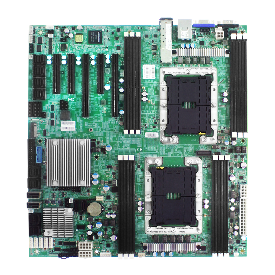
Chapter 1� Product Features Spica User Manual Chapter 1. Product Features Virgo User Manual Chapter 1. Product Features 1�1 Componenets VIRGO LGA3647 Socket P0 for LGA3647 Socket P0 for 6 x DDR4 DIMM Slots 6 x DDR4 DIMM Slots 6 Channel (from CPU1) -
Page 10: 1.2 Specifications
Virgo User Manual Chapter 1. Product Features 1.2 Specifications Intel® Xeon® Scalable Processors Processor • Intel® PCH (Lewisburg) Integrated 10GbE LAN (Platinum, Gold, Silver, Bronze) Support Controller with dual SFP+ rear connectors 9.6 GT/s, 10.4 GT/s UPI Speeds Network (KR/SFI/XFI) or 1GbE (KX) by onboard header... -
Page 11: 1�3 Feature
Chapter 1. Product Features 1�3 Feature The Virgo server board integrates two Intel® Xeon® Scalable Processors and 12 DDR4 DIMM to offer support for greater capacity, durability, and efficiency for our customers. Featuring the Intel® Xeon® Scalable Processors, which is emphasized for its compelling... -
Page 12: Chapter 2� Hardware Setup
Chapter 2� Hardware Setup Spica User Manual Virgo User Manual Chapter 2. Hardware Setup 2�1 Central Processiong Unit Setup 2�1�1 Processor Support The server board includes two processor sockets (LGA3647) that provides one or two processors of the Intel® Xeon® Processor Scalable Family and supports a Thermal Design... -
Page 13: Processor Heat Sink Module And Processor Socket Assembly
Virgo User Manual Chapter 2. Hardware Setup 2�1�2 Processor Heat Sink Module and Processor Socket Assembly Each processor socket on the server board is pre-assembled with a loading mechanism that is designed to secure the Processor Heat Sink Module (PHM) to the server board as shown below. -
Page 14: Processor Heat Sink Module
Virgo User Manual Chapter 2. Hardware Setup 2�1�3 Processor Heat Sink Module The PHM refers to the sub-assembly where the heat sink and processor are clipped together onto the server board prior to installation. The PHM consists of the components shown below. - Page 15 Virgo User Manual Chapter 2. Hardware Setup The PHM sits level with the processor socket assembly. The PHM is NOT installed properly if it does not sit level with the processor socket assembly. Once the PHM is seated over the processor socket assembly, the four heat sink torque screws must be tightened in order as shown below.
-
Page 16: 2�2 System Memory
PCIE4 PCIE3 PCIE2 PCIE1 SFF-8643 SFF-8643 NOTE -In Virgo case, the lanes from CPU#0 are routed to PCIe slots 1 & 5 and onboard SFF- 8643. -The lanes from CPU#1 are routed to PCIe slots 2/3/4 and the onboard SFF-8643. -
Page 17: Populate Dimms In The Following Order
Virgo User Manual Chapter 2. Hardware Setup 2�2�1 Populate DIMMs in the following order: JDIMML0 JDIMMC0 JDIMMK0 JDIMMB0 JDIMMJ0 JDIMMA0 DIMM Numbers DIMM ARRANGMENT CPU 0 CPU 0 CPU 1 CPU 1 CPU1 CPU0 2 DIMMs JDIMM_L0 JDIMM_C0 JDIMMG0 JDIMMD0... - Page 18 Virgo User Manual Chapter 2. Hardware Setup JDIMML0 JDIMMC0 JDIMMK0 JDIMMB0 JDIMMJ0 JDIMMA0 CPU1 CPU0 JDIMM_L0 JDIMM_C0 CPU 0 CPU 0 CPU 1 CPU 1 JDIMM_K0 JDIMM_B0 10 DIMMs JDIMM_J0 JDIMM_A0 JDIMM_G0 JDIMM_D0 JDIMMG0 JDIMMD0 JDIMM_I0 JDIMM_F0 JDIMMH0 JDIMME0 JDIMMI0...
-
Page 19: Dimm Installation Procedure
Virgo User Manual Chapter 2. Hardware Setup 2�2�2 DIMM Installation Procedure This server board supports 12 DIMM memory slots with 6 channel per CPU. 2�2�1 DIMM Installation Step 1 Unlock the dimm socket by pressing the retaining clips outward. Step 2 Insert the memory module into the slot. Make sure that the dimm notch is accurately positioned. -
Page 20: Chapter 3� Motherboard Settings
Chapter 3� Motherboard Settings Virgo User Manual Chapter 3. Motherboard Settings This section describes the jumpers, internal connectors and internal LEDs setting on Virgo motherboard. The motherboard layout and important jumper settings are listed below. 3�1 Motherboard Block Diagram Platform Environment Control Interface(PECI) -
Page 21: 3�2 Motherboard Layout
Virgo User Manual Chapter 3. Motherboard Settings 3�2 Motherboard Layout CPU 1 CPU 1 CPU 0 CPU 0 12 Dimm Sockets 38 23 42 41 58 59 60... -
Page 22: 3�3 Motherboard Content List
Virgo User Manual Chapter 3. Motherboard Settings 3�3 Motherboard Content List Connectors Location Connectors Location Power Supply JPWR1 Speaker JSPKR BIOS Recovery Power Supply JPWR2 Mode ME Force Recovery Power Supply JPWR3 Mode Flash Descriptor Power Supply JPWR4 Security override... -
Page 23: 3�4 Internal Connectors/Jumpers
Virgo User Manual Chapter 3. Motherboard Settings 3�4 Internal Connectors/Jumpers Connectors Location COM4 JCOM4 JLCM(COM3) BMC Debug Port JBMC_DP BMC GPIO JBMC_GPIO SGPIO JSGPIO BMC I2C10 JBMC_I2C10 BMC IPMI JBMC_I2C1 Intruder JINTRUDER BMC Reset JBMC_RST BMC Buzzer JBUZZER External Thermal J2 、... - Page 24 Virgo User Manual Chapter 3. Motherboard Settings JCOM4 JLCM JBMC_DP JSGPIO JBMC_GPIO I2C9SCL BMC_GPY0 +3.3V PCH_SCLOCK I2C9SDA BMC_GPY1 PCH_SDATAOUT1 PCH_SLOAD EXTRST# PCH_SDATAOUT0 JBMC_I2C10 JBMC_I2C1 I2C1SDA I2C10SDA I2C1SCL I2C10SCL JRAID_KEY JBUZZER BMC_BUZZER...
- Page 25 Virgo User Manual Chapter 3. Motherboard Settings Connectors Location SATA-DOM Power JDOM_PWR Debug Port JLPC_DP ESPI Port JESPI SSGPIO JSSGPIO PCH GPIO JPCH_GPIO VRM SMB JSMB_VR PCH FAN CONN SAS IOC ICE...
- Page 26 Virgo User Manual Chapter 3. Motherboard Settings JDOM_PWR JSSGPIO JLPC_DP JESPI JSMB_VR JPCH_GPIO SMB_VR_CLK +12V SMB_VR_DAT TACH...
- Page 27 Virgo User Manual Chapter 3. Motherboard Settings 42 41 Connectors Location Front Panel JFRNT_SSI Front USB JUSB_INT NGFF JNGFF Internal 10GbE(Reserved) J7 External Thermal J2 J13 J24 Sensor PCIE Hot-Plug JPCIE_HP PCIE Hot-Plug J4(CN5&CN6) Front Panel PCIE Hot-Plug J5(CN3&CN4) Front Panel PCIE Hot-Plug J6(CN1&CN2)
- Page 28 Virgo User Manual Chapter 3. Motherboard Settings JUSB_INT JFRNT_SS1 RSVD_2 HM_TD6- HM_TD6+ SFI_L2_RX_DP SFI_L2_TX_DP SFI_L2_RX_DN SFI_L2_TX_DN JPCIE_HP SFI_L3_RX_DP SFI_L3_TX_DP SFI_L3_RX_DN SFI_L3_TX_DN LAN_TX_FAULT3 LAN_TX_FAULT2 LAN_TX_DISABLE3 LAN_TX_DISABLE2 LAN_SDA3 LAN_SDA2 LAN_SCL3 LAN_SCL2 LAN_MOD_ABS3 LAN_MOD_ABS2 RS0/RS1_SENSE3 RS0/RS1_SENSE2 LAN_RX_LOS3 LAN_RX_LOS2 RS0/RS1_DRIVE3 RS0/RS1_DRIVE2 RSVD_1...
- Page 29 Virgo User Manual Chapter 3. Motherboard Settings JNGFF...
- Page 30 Virgo User Manual Chapter 3. Motherboard Settings...
- Page 31 Virgo User Manual Chapter 3. Motherboard Settings Connectors Location Power Supply JPWR3 Power Supply JPWR4 PMBUS JPMBUS CPU0 FAN CONN FAN1A CONN FAN1B CONN FAN2A CONN FAN2B CONN FAN3A CONN FAN3B CONN SAS IOC UART SAS IOC ACTIVITY SAS IOC ERROR...
- Page 32 Virgo User Manual Chapter 3. Motherboard Settings JPWR3 JPWR4 JPMBUS +12V +12V +3.3V +12V +12V +12V +12V TACH +12V PMBUS_ALERT_N +12V +12V SMB_PMBUS_DATA SMB_PMBUS_CLK SAS3008_1V8 UART0_RX +12V TACH UART0_TX PRSNT_N FAULT +3.3V SAS_PHY0 Error LED SAS_PHY4 Error LED SAS_PHY1 Error LED...
- Page 33 Virgo User Manual Chapter 3. Motherboard Settings CPU 1 CPU 1 Connectors Location Power Supply JPWR1 Power Supply JPWR2 Power Supply JPWR5 JVGA_INT COM1 JCOM1 External Thermal J2 J13 J24 Sensor CPU1 FAN CONN JPWR1 JPWR2 JPWR5 +12V +12V JCOM1...
- Page 34 Virgo User Manual Chapter 3. Motherboard Settings 38 23 Connectors Location Clear CMOS JCMOS BMC Reset JBMC_RST BMC Disable JBMC_DIS System PG Lock JPG_LOCK Speaker JSPKR BIOS Recovery Mode ME Force Recovery Mode Flash Descriptor Security override No Reboot (Watch Dog)
- Page 35 Virgo User Manual Chapter 3. Motherboard Settings JBMC_RST JBMC_DIS CMos Setting JBMC_DIS Setting JBMC_RST Setting Pin1-2 Normal Default Short Reset BMC Short Disable Pin3-4 Clear CMOS Open Normal Defualt Open Normal Defualt JPG_LOCK Setting JPG_LOCK Setting Short BIOS Recovery mode...
-
Page 36: 3�5 Leds
Virgo User Manual Chapter 3. Motherboard Settings 3�5 LEDs 3.5.1 Front Panel LED Definition Yellow The system is On. The system is in Standby; System is off, Power Blinking but has AC power. System has no AC power Blue UID activity detected. -
Page 37: 3.5.3 Internal Leds Definition
Virgo User Manual Chapter 3. Motherboard Settings 3.5.3 Internal LEDs Definition CPU 1 CPU 1 LAN1 10G LED CPU 0 CPU 0 LAN2 10G LED LAN1 1G LED LAN2 1G LED LAN4 10G/1G LED LAN3 10G/1G LED BMC Heart Bit LED... -
Page 38: Chapter 4. Bios Configuration Settings
Chapter 4. BIOS Configuration Settings Virgo User Manual Chapter 3. Motherboard Settings This chapter demonstrates how to configure the UEFI BIOS settings in your system device. You can enter the BIOS screen during system startup. To enter BIOS configuration settings, •... -
Page 39: 4�2 Bios Setup
Virgo User Manual Chapter 3. Motherboard Settings 4�2 BIOS Setup 4�2�1 Menu Press and to select the options of the menu bar. Press Enter to access the option screen. Menu Description Main Displays basic system information and date & time. - Page 40 Virgo User Manual Chapter 4. BIOS Configuration Settings Step 2 There will be a message “Entering SETUP” displayed on the diagnostics screen. Step 3 Identify the BIOS version. CAUTION For the official released version, the last digit of the BIOS version must end in a “0.“...
- Page 41 Virgo User Manual Chapter 4. BIOS Configuration Settings Step 4 Load Optimal Default Setting. Step 5 Save the setting and exit the BIOS setup utility.
-
Page 42: Update
Virgo User Manual Chapter 4. BIOS Configuration Settings 4�2�3 Update To identify the latest BIOS version, please check the BIOS setup. - Page 43 Virgo User Manual Chapter 4. BIOS Configuration Settings Update BIOS by INSYDE H2OFFT-D utility under DOS environment If you need to update Flash in the DOS environment, please use H2OFFT-D utility. To use this utility, you must include the flash.bat , H2OFFT-D.exe, and bin file in the same folder.
-
Page 44: 4�3 Main
Virgo User Manual Chapter 4. BIOS Configuration Settings 4�3 Main Main Option Key: 4�3�1 Main Option Key Description System time Configures the current time. System date Configures the current date. -
Page 45: 4�4 Advanced
Virgo User Manual Chapter 4. BIOS Configuration Settings 4�4 Advanced Advanced Option Key: 4.4.1 Peripheral Configuration Peripheral Configuration PCIe SR-IOV Enable Disable PCIe ARI Enable Disable ARI Forward Enable Disable Spread Enable Disable Spectrum Redfish On/ Enable Disable 4.4.2 Video Configuration... - Page 46 Virgo User Manual Chapter 4. BIOS Configuration Settings MSR Lock Control Enable Disable Processor Configuration Extended APIC Enable Disable 128M 256M MMCFG Size 512M Common MMIO High Base RefCode Configuration MMIO High Granularity Size 256G 1024G Disable Minimum Serial Debug Message...
- Page 47 Virgo User Manual Chapter 4. BIOS Configuration Settings Check Platform Detect Enable Disable Erase-Arm NVDIMMs Enable Disable Restore NVDIMMs Enable Disable Memory Configuration Interleave NVDIMMs Enable Disable Custom Refresh Rate Min=0, Max=40 Auto 100 KHz SMB Clock Frequency 400 KHz...
- Page 48 Virgo User Manual Chapter 4. BIOS Configuration Settings Single Power Enable Disable Domain (SPD) Max Performance Boot performance Max Efficient mode Set by Intel Node Manager CPU P State Control Energy Enable Disable Efficient Turbo Turbo Mode Enable Disable CPU Flex Ratio...
-
Page 49: 4.4.4 Pch Configuration
Virgo User Manual Chapter 4. BIOS Configuration Settings 4.4.4 PCH Configuration PCH Configuration PCH Devices PCH state after G3 Last State SATA Controller Configure SATA as AHCI RAID Support Aggressive Link Power Enable Disable Management Alternate Device ID on Enable... - Page 50 Virgo User Manual Chapter 4. BIOS Configuration Settings Smart Response Enable Disable Technology PCH SATA Configuration 2 Seconds 4 Seconds RAID OROM prompt delay 6 Seconds 8 Seconds sSATA Controller Enable Disable Configure sSATA as AHCI RAID Support Aggressive Link Power...
- Page 51 Virgo User Manual Chapter 4. BIOS Configuration Settings SLP_LAN# Low on DC Enable Disable Power K1 off Enable Disable FPK Port 1-4 Enable Management Disable PCI Delay Enable Disable Optimization Compliance Test Enable Disable Mode PCI-E ASPM Support Per individual port...
- Page 52 Virgo User Manual Chapter 4. BIOS Configuration Settings Enable Disable Enable Disable Enable Disable NFER Enable Disable Enable Disable SEFE Enable Disable SENFE Enable Disable SECE Enable Disable PME SCI Enable Disable Hot Plug Enable Disable Advanced Error Enable Disable...
-
Page 53: 4.4.5 H2O Ipmi Configuration
Virgo User Manual Chapter 4. BIOS Configuration Settings Auto Non Snoop Latency Manual Override Disable Non Snoop Min=0, Max=102 Latency Value PCH sSATA PCH PCIe LTR Configuration Configuration 1 ns 32 ns Non Snoop Latency 1024 ns 32768 ns Multiplier... -
Page 54: H2O Event Log Config Manager
Virgo User Manual Chapter 4. BIOS Configuration Settings 4.4.6 H2o Event Log Config Manager H2o Event Log Config Manager Console Serial Enable Disable Redirect VT_100 VT_100+ Terminal Type VT_UTF8 PC_ANSI 1200 2400 4800 9600 Baud Rate 19200 38400 57600 115200... -
Page 55: 4�5 Security
Virgo User Manual Chapter 4. BIOS Configuration Settings 4�5 Security Security Option Key: 4�5�1 Security Security Current TPM Not Detected TPM 1.2 TPM 2.0 Device TrEE Protocol Version Available Hidden Availability No operation Disable and Deactivate Enable and Activate Operation... -
Page 56: 4�6 Power
Virgo User Manual Chapter 4. BIOS Configuration Settings 4�6 Power Power Option Key: 4�6�1 Power Power Wake on PME Enable Disable... -
Page 57: 4�7 Boot
Virgo User Manual Chapter 4. BIOS Configuration Settings 4�7 Boot Boot Option Key: 4�7�1 Boot Boot Boot Type Dual Boot Type Legacy Boot Type UEFI Boot Type Quick Boot Enable Disable Quiet Boot Enable Disable Network Stack Enable Disable PXE Boot to... -
Page 58: 4�8 Exit
Virgo User Manual Chapter 4. BIOS Configuration Settings 4�8 Exit Exit Option Key: 4�8�1 Exit Save and Exit Exit Saving Changes Exit system setup and save your changes. Save Change Without Save your changes without exiting the system. Exit Exit Discarding Discard your changes when existing the system. -
Page 59: Chapter 5. Bmc Configuration Settings
Chapter 5. BMC Configuration Settings Spica User Manual Virgo User Manual Chapter 5. BMC Configuration Settings Insert Ethernet LAN cable into the BMC LAN port. There are two methods to setup BMC IP: BMC management port (Dedicated NIC channel 1 ) 5�1 Method 1 (Use the BIOS Setup) - Page 60 Virgo User Manual Chapter 5. BMC Configuration Settings...
- Page 61 Virgo User Manual Chapter 5. BMC Configuration Settings Step 3 Input the subnet mask address.
-
Page 62: 5�2 Method 2 (Use A Dos Tool - Syscheck)
Virgo User Manual Chapter 5. BMC Configuration Settings 5�2 Method 2 (Use a Dos Tool - Syscheck) Step 1 Type in "sc –lanset." Step 2 Modify the IP setting. NOTE Type 1 for selecting static IP Mode or Type 2 for selecting DHCP Mode. - Page 63 Virgo User Manual Chapter 5. BMC Configuration Settings Step 4 Input the submask address. The IP address below is an example using the default IP setting. The IP address is configurable. Step 5 Complete the BMC IP configuration. NOTE Type sc.exe ─ langet command to obtain BMC IP and Mac address.
-
Page 64: 5�3 Connect To Bmc
Virgo User Manual Chapter 5. BMC Configuration Settings 5�3 Connect to BMC NOTE This feature works with JAVA 6 Runtime installed Console Environment. The IP address below is an example using the default IP setting. The IP address is configurable. - Page 65 Virgo User Manual Chapter 5. BMC Configuration Settings Dashboard: The Dashboard page gives the overall information about the status of a device. Server Health - Sensor Readings: Then Sensors Readings page displays all the sensor related information. Settings: The Settings page allows you to access various configuration settings.
- Page 66 Virgo User Manual Chapter 5. BMC Configuration Settings KVM Mouse Setting: The KVM Mouse Setting page displays the setting for mouse emulation from local window to remote screen. • For Windows OS environment, set mode to absolute. • For Linux OS environment, set mode to relative.
- Page 67 Virgo User Manual Chapter 5. BMC Configuration Settings Environmental setting:...
-
Page 68: 5�4 Updating Bmc Firmware
A:>cd SB301C01 A:\ SB301C01>a.bat This is just an example. The latest BMC firmware version is available from the FAE or AIC website. Step 4 After updating the BMC firmware, please turn off and restart the Example: system. NOTE 1. Do not use EMM386 in Dos environment when updating the firmware or you will receive a system failure. -
Page 69: Chapter 6� Technical Support
Chapter 6� Technical Support Taiwain, Global Headquarters North California, United States Address: 48531 Warm Springs Address: No� 152, Section 4, Boulvard Suite 404 Fremont, CA Linghang N� Rd, Dayuan District, 94539, United States Taoyuan City 337, Taiwan Tel: +886-3-433-9188 Tel: +1-510-573-6730 Fax: +886-3-287-1818 Fax: +1-510-573-6729 Sales Email: sales@aicipc�com�tw...
Need help?
Do you have a question about the Virgo and is the answer not in the manual?
Questions and answers