Table of Contents
Advertisement
Quick Links
Advertisement
Table of Contents

Subscribe to Our Youtube Channel
Related Manuals for AIC Lepus


Summary of Contents for AIC Lepus
- Page 1 Lepus Server Motherboard User's Manual UM_Lepus_v2.2_112618...
-
Page 2: Table Of Contents
Table of Contents Preface ������������������������������������������������������������������������������������������������� i Safety Instructions ������������������������������������������������������������������������������ ii About This Manual ������������������������������������������������������������������������������ iii Chapter 1� Product Features �������������������������������������������������������������� 1 1.1 Components ..................... 1 1.2 Specifications ..................2 1.3 Feature ..................... 3 Chapter 2� Hardware Setup ���������������������������������������������������������������� 4 2.1 Central Processing Unit (CPU) ..............4 2.1.1 Processor Support ....................4 2.1.2 Installing the CPU ....................4 2.1.3 CPU Heatsink Installation ..................7... - Page 3 4.4.4 Hardware Health Configuration ..............20 4.4.5 Super IO Configuration ..................20 4.4.6 S5 RTC Wake Settings ..................21 4.4.7 Serial Port Console Redirection ..............21 4.4.8 CPU Configuration ................... 22 4.4.9 SATA Configurations ..................22 4.4.10 PCI Subsystem Settings ................23 4.4.11 CSM Configuration ..................
- Page 4 5.2.9 Remote Control ....................39 5.2.10 Power Control ....................44 5.2.11 Chassis Identify Control ................45 5.2.12 Set Front Panel Enables ................45 5.2.13 Maintenance ....................46 5.2.14 Sign out ......................48 Chapter 6� Technical Support ����������������������������������������������������������� 49 Contents...
- Page 5 Document Release History Release Date Version Update Content April User's Manual release to public. 2018 1. New cover September 2. Correct grammar error 2018 3. Connector and jumper update Novemer 1. Motherboard settings update 2. Datasheet 2018 Contents...
- Page 6 Copyright © 2018 AIC, Inc� All Rights Reserved� This document contains proprietary information about AIC products and is not to be disclosed or used except in accordance with applicable agreements.
-
Page 7: Preface
Disclaimer AIC shall not be liable for technical or editorial errors or omissions contained herein. The information provided is provided "as is" without warranty of any kind. To the extent permitted by law, neither AIC or its affiliates, subcontractors or suppliers will be liable for incidental, special or consequential damages including downtime cost;... -
Page 8: Safety Instructions
Safety Instructions When installing, operating, or performing maintenance on this equipment, the following safety precautions should always be taken into account in order to reduce the risk of fire, electric shock, and personal injury. Carefully read the safety instructions below before using this product. •... -
Page 9: About This Manual
This document pellucidly presents a brief overview of the product design, device installation, and firmware settings for the Lepus motherboard. For the latest version of this user's manual, please refer to the AIC website: http://www.aicipc.com/rus/productdetail/50982. -
Page 10: Chapter 1� Product Features
Ursa User Manual Chapter 1. Product Features Lepus User Manual Chapter 1. Product Features This section describes the hardware specifications and features of the Lepus motherboard. The fundamental components of the Lepus severboard are provided below. 1�1 Components Lepus Serverboard... -
Page 11: Specifications
Lepus User Manual Chapter 1. Product Features 1.2 Specifications Aspeed AST2400 Advanced PCIe Graphics & Processor Remote Management Processor Support IPMI CPU TDP Serial over LAN Socket Socket H3 (LGA-1151) On-board Type support dual port GbE System Devices Chipset for quad port GbE (BTO) - Page 12 The Lepus series server board delivers unmatched performance, providing support with two channels of DDR4 2400/2133 Unbuffered ECC UDIMM, Up to 4x1GBase-T, and optional Broadcom/LSI SAS 3008 IOC onboard. Lepus series server board enables next generation server solutions with an incredible leap in performance in a standard ATX form factor platform.
-
Page 13: Chapter 2� Hardware Setup
Chapter 2� Hardware Setup Chapter 2. Hardware Setup Lepus User Manual 2.1 Central Processing Unit (CPU) 2�1�1 Processor Support The server board includes one processor socket H3 (LGA1151) that provides support for more than two CPU types and a Thermal Design Power(TDP) of up to 80W on selected models. - Page 14 Lepus User Manual Chapter 2. Hardware Setup Step 2 While holding down the lever handle, with your other hand, lift open the Load Plate. Load plate Step 3 Remove the protective cover from the CPU socket. Do not throw away the protective cover.
- Page 15 Chapter 2. Hardware Setup Lepus User Manual Step 5 Close the loading plate by pushing down the locking lever on the side. Slide the tip of the lever under the notch on the loading plate. Make sure the loading plate tab engages under the socket lever when fully closed.
-
Page 16: Cpu Heatsink Installation
Lepus User Manual Chapter 2. Hardware Setup 2�1�3 CPU Heatsink Installation Step 1 Apply thermal grease onto the heatsink and position the heatsink onto the CPU socket. Make certain that the heatsink is accurately positioned. Step 2 Tighten the four screws in a diagonal sequence. Secure the screws a couple of turns until the screws are tightly secured and the heatsink is fastened onto the server board. -
Page 17: System Memory Setup
Chapter 2. Hardware Setup Lepus User Manual 2�2 System Memory Setup This server board supports 4 DIMM memory slots with 2 channel per CPU. 2�2�1 DIMM Installation Step 1 Unlock the dimm socket by pressing the retaining clips outward. Step 2 Insert the memory module into the slot. Make sure that the DIMM notch is accurately positioned. -
Page 18: Dimm Location
Lepus User Manual Chapter 2. Hardware Setup 2�2�2 DIMM Location 2�2�3 Dimm Slot Installation Order Populate the DIMM slots in the following order. DIMM NUMBER DIMM ARRANGEMENT JDIMMB1 JDIMMB0 CPU0 JDIMMA1 JDIMMA0 2 DIMMs JDIMM_A0 JDIMM_B0 CPU1 JDIMMB1 JDIMMB0 DIMM NUMBER... -
Page 19: Chapter 3� Motherboard Settings
Lepus User Manual Chapter 3. Motherboard Settings This section provides illustrations that display the internal jumpers, connectors, and system LED indicators on the Lepus motherboard. The motherboard layout and essential connectors are listed below for your reference. 3�1 Block Diagram VCCcore = PXC1410A + TDA2132 x4 Mini-SAS HD Conn. -
Page 20: Content List
Lepus User Manual Chapter 3. Motherboard Settings 3�2 Content List Connector/Jumper/Header Location Connector/Jumper/Header Location DIMM_A0 (DDR4, SATA Port (SATA 3.0, 6 J8C1 SATA3, J43 Blue, Address:0xA0) Gbit/s) SATA Port (SATA 3.0, 6 CPU Fan, PIN Header SATA4, J42 Gbit/s) System FAN5 Pin SATA Port (SATA 3.0, 6... - Page 21 Lepus User Manual Chapter 3. Motherboard Settings Connector/Jumper/Header Location Connector/Jumper/Header Location LAN3, LAN4 Port (RJ- PCI Express Slot (x1 45)*2 OPTIONAL WITH Slot, w/x1 link) LSI SAS3008 Action LED1 USB Port (USB 3.0)*2 LED, Green LSI SAS3008 Error VGA Port (D-Sub) /...
-
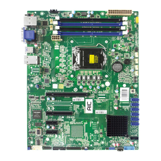
Page 22: Layout
Lepus User Manual Chapter 3. Motherboard Settings 3�3 Layout 1 2 3 4... -
Page 23: Connector And Jumper
Lepus User Manual Chapter 3. Motherboard Settings 3�4 Connector and Jumper 2 CPU Fan: J14 23 SATA SGPIO Pin 26 Front USB2�0 Header Header: J34 (blue): FP_USB_1 10 11 12 13 3 System Fan 1/Fan2/Fan3/ Fan4/Fan5: J50,J49, J48, J47, J15... - Page 24 Lepus User Manual Chapter 3. Motherboard Settings 33 Front Panel Header: 45 SPI Bus Select Jumper: J111 VCC3_AUX PWRLED+ IDLED+ IDLED- PWRLED- Setting J111 SYS_FAULT1- HDDLED+ PCH to SPI Default Pin1-3 and 4-6 Closed SYS_FAULT2- HDDLED- BMC to SPI Pin2-4 and 3-5 Closed...
-
Page 25: Chapter 4. Bios Configuration Settings
Chapter 4. BIOS Configuration Settings Lepus User Manual Chapter 4. BIOS Configuration Settings This chapter demonstrates how to configure the UEFI BIOS settings in your system device. You can enter the BIOS screen during system startup. To start the BIOS setup utiility, •... -
Page 26: Bios Menu
Lepus User Manual Chapter 4. BIOS Configuration Settings 4�2 BIOS Menu Press and to select the options of the menu bar. Press Enter to access the option screen. Menu Description Displays system information such as CPU bus speed, system memory speed, total installed Main memory, current EFI language, and system date &... -
Page 27: Main
Lepus User Manual Chapter 4. BIOS Configuration Settings 4�3 Main Lepus Main Option Key: 4�3�1 Main Main System time Configures current time. System date Configures current date. -
Page 28: Advanced
Lepus User Manual Chapter 4. BIOS Configuration Settings 4�4 Advanced Advanced Option Key: 4�4�1 Trusted Computing Displays Trusted Computing settings. Trusted Computing Security Device Support Enable Disable 4�4�2 APCI Settings Displays system ACPI parameters. ACPI Settings Security Device Support Enable... -
Page 29: Onboard Device Configuration
Lepus User Manual Chapter 4. BIOS Configuration Settings 4.4.3 Onboard Device Configuration Displays Onboard Device Configuration. Onboard Device Configuration Onboard LAN #1 Onboard LAN #2 Enable Disable Onboard LAN #3 Onboard LAN #4 Load Onboard LAN#1 Option ROM Load Onboard LAN#2... -
Page 30: S5 Rtc Wake Settings
Lepus User Manual Chapter 4. BIOS Configuration Settings 4�4�6 S5 RTC Wake Settings Enable system to wake from S5 using RTC alarm. S5 RTC Wake Settings Disable Fixed Time Dynamic Time Wake up hour Select 0-23. Wake up minute Wake System from S5 Wake up Minute Select 0-59 for Minute. -
Page 31: Cpu Configuration
Lepus User Manual Chapter 4. BIOS Configuration Settings Out-of-Band COM1 Mgmt Port VT-UTF8 VT100 Terminal Type VT100+ ANSI Serial Port for Out-Of- 115200 9600 Band Management/ Bits per Second Windows Emergency 19200 57600 Services (EMS) Console Hardware RTS/ Software Xon/... -
Page 32: Pci Subsystem Settings
Lepus User Manual Chapter 4. BIOS Configuration Settings 4�4�10 PCI Subsystem Settings Displays PCI, PCI-X and PCI Express settings. PCI Subsystem Settings Above 4G Decoding Enable Disable 4�4�11 CSM Configuration Displays CSM configuration: Enable/Disable, Option ROM execution settings, and etc. -
Page 33: Chipset
Lepus User Manual Chapter 4. BIOS Configuration Settings 4�5 Chipset Chipset Option Key: 4.5.1 Intel Server Platform Services Configuration Displays Intel Server Platform Services Parameters. Intel Server Platform Services Configuration Intel Server Platform Enable Disable Services Power Measurement Enable Disable... -
Page 34: South Bridge Configuration
Lepus User Manual Chapter 4. BIOS Configuration Settings 4.5.3 South Bridge Configuration Displays PCH Parameters. South Bridge Configuration Intel PCH RC Version Read only. Intel PCH SKU Name Read only. Intel PCH Rev ID Read only. DeepSx Power Policies Enable in S4-S5... -
Page 35: Security
Lepus User Manual Chapter 4. BIOS Configuration Settings 4.6 Security Security Option Key: 4�6�1 Security Security Administrator Password Set administrator password in the Create New Password window. After you key in the password, the Confirm New Password window will pop out to ask for confirmation. -
Page 36: Server Management
Lepus User Manual Chapter 4. BIOS Configuration Settings 4�7 Server Management Server Management Option Key: 4�7�1 FRB-2 Timer FRB-2 Timer: Configures FRB-2 timer (POST timer). FRB-2 Timer timeout: Enter value Between 3 to 6 min for FRB-2 Timer Expiration value. -
Page 37: Os Watchdog Timer
Lepus User Manual Chapter 4. BIOS Configuration Settings OS Watchdog OS Watchdog Timer Enable Disable OS Wtd Timer timeout 5 minutes 10 minutes 15 minutes 20 minutes OS Wtd Timer Policy Do Nothing Reset Power Down Power Cycle 4�7�3 System Event Log... -
Page 38: Boot
Lepus User Manual Chapter 4. BIOS Configuration Settings 4�8 Boot Boot Option Key: 4�8�1 Boot Setup Prompt Timeout: Displays the number of seconds to wait for setup activation key. Bootup NumLock State:Select the keyboard NumLock state. Quiet Boot:Configures Quiet Boot option. -
Page 39: Save And Exit
Lepus User Manual Chapter 4. BIOS Configuration Settings 4�9 Save and Exit Save and Exit Option Key: 4�9�1 Save and Exit Save and Exit Save Changes and Exit Exit system setup after saving the changes. Discard Changes and Exit system setup without saving any changes. -
Page 40: Chapter 5. Bmc Configuration Settings
Chapter 5. BMC Configuration Settings Lepus User Manual Chapter 5. BMC Configuration Settings 5�1 Login NOTE This feature works with the JAVA 6 run time installed console environment. The IP address below is an example using the default IP setting. The IP address is configurable. -
Page 41: Web Gui
Lepus User Manual Chapter 5. BMC Configuration Settings 5�2 Web GUI 5�2�1 Menu Bar Click to select the options of the menu bar. Menu Description The Dashboard page gives the overall information about the status of a Dashboard device. Sensor The Sensor Readings page displays all the sensor related information. - Page 42 Lepus User Manual Chapter 5. BMC Configuration Settings 5�2�2 User Information and Quick Button The user information and quick access buttons are located at the top right corner. It displays the logged-in user, his/her privilege and the four quick buttons allowing you to perform different functions.
- Page 43 Lepus User Manual Chapter 5. BMC Configuration Settings 5�2�3 Dashboard The Dashboord page displays device, system, and network information. Click Dashboard on the menu bar to view the overall information of the server. 5�2�4 Sensor The Sensor page displays the status and records on related sensors.
- Page 44 Lepus User Manual Chapter 5. BMC Configuration Settings 5�2�5 System Inventory The System Inventory page displays network information, including Vendor name, Model, and Sofware version. Click System Inventory on the menu bar to open. 5�2�6 FRU Information The FRU Information page displays Basic Information, Chassis Information, Board Information and Product Information of the FRU device.
- Page 45 Lepus User Manual Chapter 5. BMC Configuration Settings 5�2�7 Logs and Reports The System Inventory page displays IPMI Event Log and Video Log. Click Logs and Reports from the menu bar → select Event Log or Video Log to view the contents.
- Page 46 Lepus User Manual Chapter 5. BMC Configuration Settings 5�2�8 Settings The Settings page displays the configuration settings for Date & Time, External User Services, KVM Mouse Setting, Log Settings, Media Redirection Settings, Network Settings, PAM Order Settings, Platform Event Filter, Services, SMTP Settings, SSL...
- Page 47 Lepus User Manual Chapter 5. BMC Configuration Settings Settings Menu and Option Keys: Settings Date and Time LDAP/E-directory Active directory Radius Settings Settings Settings External User Services General Advanced General Role General Role Radius Radius Settings Groups Settings Groups Settings...
- Page 48 Lepus User Manual Chapter 5. BMC Configuration Settings 5�2�9 Remote Control The Remote Control page displays the configuration for power control and remote KVM. Click Java Console to start the JViewer video redirection.
- Page 49 Lepus User Manual Chapter 5. BMC Configuration Settings Click Launch KVM to open the Remote KVM page.
- Page 50 Lepus User Manual Chapter 5. BMC Configuration Settings Procedure To Start KVM Step 1 Click Start KVM to start the H5Viewer video redirection. Step 2 Click Browse to select CD Image. Step 3 Click Start Media to redirect the selected CD image file to the Host.
- Page 51 Lepus User Manual Chapter 5. BMC Configuration Settings Remote KVM Menu and Option Keys: Button Description Start KVM Starts the H5Viewer video redirection. Stop KVM Stops the H5Viewer video redirection. Pause Video This option is used for pausing Console Redirection.
- Page 52 Lepus User Manual Chapter 5. BMC Configuration Settings This menu item can be used to act as the Right <Ctrl> right-side <CTRL> key when in Console Redirection. This menu item can be used to act as Right <Alt> the right-side <ALT> key when in Console Redirection.
- Page 53 Lepus User Manual Chapter 5. BMC Configuration Settings 5�2�10 Power Control The Power Control page allows you to view and control the power of your server. To open Power Control, click Power Control from the menu bar. The various options of Power Control are given below.
- Page 54 Lepus User Manual Chapter 5. BMC Configuration Settings 5�2�11 Chassis Identify Control The Chassis Identify Control page displays the BMC’s UID control information. Users can change the Identify LED behavior on this page. Click Chassis Identify Control from the menu bar. Select Off/On to control UID LED.
- Page 55 Lepus User Manual Chapter 5. BMC Configuration Settings 5�2�13 Maintenance This Maintenance page displays the configuration settings for Backup Configuration, Firmware Image Location, Firmware Information, BIOS Information, Fimware Update, Preserve Configuration, Restore Configuration, Restore Configuration, and Restore Factory Defaults.
-
Page 56: Maintenance
Lepus User Manual Chapter 5. BMC Configuration Settings Maintenance Procedure 1. Click Check All to backup the selected configuration items. The Backup Configuration page will appear Click Download Config to save the backup file to the client system Backup Configuration 2. -
Page 57: Sign Out
Lepus User Manual Chapter 5. BMC Configuration Settings 5�2�14 Sign out To log out of the BMC: Method 1: Click Sign out from the menu bar. The Logout dialog box will pop out. Method 2: Click the root quick button on the top right corner of the screen. -
Page 58: Chapter 6� Technical Support
Chapter 6� Technical Support Taiwain, Global Headquarters South California, United States Address: No� 152, Section 4, Address: 21808 Garcia Lane Linghang N� Rd, Dayuan District, City of Industry, CA 91789, Taoyuan City 337, Taiwan United States Tel: +886-3-433-9188 Toll free: +7-4997019998 Fax: +886-3-287-1818 Tel: +1-909-895-8989 Sales Email: sales@aicipc�com�tw...
Need help?
Do you have a question about the Lepus and is the answer not in the manual?
Questions and answers