Table of Contents
Advertisement
Quick Links
Advertisement
Table of Contents

Related Manuals for AIC Libra


Summary of Contents for AIC Libra
- Page 1 Libra Server MotherBoard User Manual Document Number: MAN-00207-A ...
-
Page 2: Table Of Contents
Contents Contents ................................ 0 Safety Information ............................. 2 About This User Manual ............................. 3 Chapter 1. ................................ 4 1.1 General Information ........................ 4 1.2 Specifications ............................ 4 Chapter 2. ................................ 6 2.1 Central Processing Unit (CPU) ....................... 6 ... -
Page 3: Safety Information
Safety Information When installing, operating, or performing maintenance on this equipment, basic safety precautions, as listed below, should always be followed to reduce the risk of fire, electric shock, and personal injuries. Read and understand all instructions. Observe warnings and instructions marked on the product. ... -
Page 4: About This User Manual
About This User Manual This document provides a detailed description of the Libra including: The General Features of the Product Motherboard Settings BIOS Configuration and Settings BMC Configuration and Settings ... -
Page 5: Chapter 1
Chapter 1. Product Introduction 1.1 General Information Libra, a server grade mother board supports two Intel Xeon processor E5-2600 V3 ® ® series. 1.2 Specifications Dimensions (with chassis ears/protrusions) mm : 305 x 330 W x D inches : 12 x 13... - Page 6 • 4 memory channels per CPU socket, 4 channels with 2DPC • 16 DIMM slots support up to: System Memory - 256GB (@4Gb) / 512GB (@8Gb) DDR4 1866/2133 RDIMM SR, DR - 512GB (@4Gb) / 1024GB (@8Gb) DDR4 2133 LRDIMM QR BIOS •INSYDE 16MB BIOS Type...
-
Page 7: Chapter 2
Chapter 2. Hardware Setup 2.1 Central Processing Unit (CPU) Caution : When unpacking a processor, hold the processor only by its edges to avoid touching the contacts. 2.1.1 Installing the CPU 1. Press the load lever to release the load plate. ... - Page 8 3. Remove the processor protective cover from CPU socket. Processor protective cover 4. Align the processor cutouts against the socket notches. Cutouts Caution: The pins of the processor socket are vulnerable and easily susceptible to damage if fingers or any foreign objects are pressed against them.
- Page 9 2.1.2 Installing the CPU Heatsink Note: Apply thermal paste to the bottom of heatsink and spread in an even thin layer before installing the heatsink. To install the CPU heatsink: 1. Place the heatsink on top of the CPU, ensuring that the four fasteners match the holes on the motherboard.
-
Page 10: System Memory
2.2 System Memory This server board supports up to sixteen DDR4 1333/1600/1866/2133 Registered ECC SDRAM(RDIMM) / Load-Reduced DIMM (LRDIMM). ... - Page 11 Populate DIMMs in the following order: DIMM DIMM arrangement Numbers CPU1 JCPU0 2 DIMMs JDIMM_G0 JDIMM_A0 CPU1 JCPU0 4 DIMMs JDIMM_G0 JDIMM_A0 JDIMM_H0 JDIMM_B0 CPU1 JCPU0 JDIMM_G0 JDIMM_A0 6 DIMMs JDIMM_H0 JDIMM_B0 JDIMM_E0 JDIMM_C0 CPU1 JCPU0 JDIMM_G0 JDIMM_A0 8 DIMMs JDIMM_H0 JDIMM_B0 JDIMM_F0...
- Page 12 CPU1 JCPU0 JDIMM_G0 JDIMM_A0 JDIMM_G1 JDIMM_A1 12 DIMMs JDIMM_H0 JDIMM_B0 JDIMM_H1 JDIMM_B1 JDIMM_F0 JDIMM_D0 JDIMM_E0 JDIMM_C0 CPU1 JCPU0 JDIMM_G0 JDIMM_A0 JDIMM_G1 JDIMM_A1 JDIMM_H0 JDIMM_B0 14 DIMMs JDIMM_H1 JDIMM_B1 JDIMM_F0 JDIMM_D0 JDIMM_E1 JDIMM_C1 JDIMM_E0 JDIMM_C0 CPU1 JCPU0 JDIMM_G0 JDIMM_A0 JDIMM_G1 JDIMM_A1 JDIMM_H0...
- Page 13 Unlock a DIMM socket by pressing the retaining clips outward. Insert module vertically and press down until it snaps into place. Note: DIMM notch and socket bump must align as shown. DIMM notch ...
-
Page 14: Chapter 3
Chapter 3. Motherboard Settings This section describes the jumpers, internal connectors, and internal LEDs setting on Libra motherboard. Motherboard layout and important jumper settings are listed as below. 3.1 Motherboard block diagram ... -
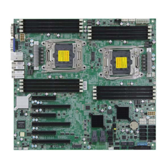
Page 15: Motherboard Layout
3.2 Motherboard Layout ... -
Page 16: Motherboard Content List
3.3 Motherboard Content List Connectors Location Connectors Location Ethernet (Single Port) LAN1,LAN2 Intruder JINTRUDER Ethernet (Dual Port) RJ45 PMBUS JPMBUS USB Port (Dual Port) USB3.0 SPI ROM Socket JSPI COM Port Speaker JSPKR VGA Port BMC Reset JBMC_RST Power Supply (4x2 pin) JPWR1 BMC Disable JBMC_DIS... -
Page 17: Internal Connectors/Jumpers
3.4 Internal Connectors/Jumpers ... - Page 18 Connectors/Jumpers Description 1. +3.3V_DUAL 13. GND 2. +3.3V_DUAL LAN1_TRAFFIC KEY (no pin) SW_RST_BTN# +5V_AUX I2C8SDA PWR_LED# 17. GND UIDLED_OUT# I2C8SCL JFRNT SSI SSI Front Panel 7. +3.3V UID_SW_IN# SYS_HEALTH#2 INTRUDER# ...
- Page 19 1. GND 4. PWM1 Fan Header 2. +12V 5. FAN1B_RSNT_N 3. FAN2_TACH 6. LED_FAN1B_FAULT 1. GND 4. PWM3 Fan Header 2. +12V 5. FAN3B_PRSNT_N 3. FAN6_TACH 6. LED_FAN3B_FAULT 1. GND 4. PWM3 Fan Header 2. +12V 5. FAN3A_PRSNT_N 3. FAN5_TACH 6.
- Page 20 Internal Connectors/Jumpers (Continued) ...
- Page 21 Connectors/Jumpers Description 1.+3.3V 6. PCH_SPI_CLK 2.GND 7. PCH_LDRQ0_N JTPM Debug Port 3. PCH_SPI_MOSI 8. PCH_SPI_CS1_N 4. PCH_SPI_MISO 9. RST_PLTRST_N 5. PCH_GPIO23 10. PCH_SPI_CS2_N 1. GND 4. PCH_SLOAD JSGPIO SGPIO 2. PCH_SDATAOUT0 5. +3.3V 3. PCH_SDATAOUT1 6. PCH_SCLOCK 1. GND 4.
- Page 22 3. MDI_P0 8. MDI_P2 4. MDI_N1 9. MDI_P3 5. +1V5_DUAL_LAN4 10. MDI_N2 1. MDI_N0 6. GND 2. MDI_P1 7. MDI_N3 JLAN1 LAN4 Header 3. MDI_P0 8. MDI_P2 4. MDI_N1 9. MDI_P3 5. +1.0V_PHY_I217 10. MDI_N2 1. DSRB 2. DCDB 3.
- Page 23 A1.NC C1.SIO0_SAS_DIN A2.SIO0_SAS_CLK C2.GND A3.GND C3.GND A4.SAS_EXP_RX_P2 C4. SAS_EXP_TX_P2 A5. SAS_EXP_RX_N2 C5. SAS_EXP_TX_N2 A6.GND C6.GND A7. SAS_EXP_RX_P3 C7. SAS_EXP_TX_P3 A8. SAS_EXP_RX_N3 C8. SAS_EXP_TX_N3 A9.GND C9.GND SFF-8643 CONN B1.GND D1.SIO0_SAS_DOUT B2.SIO0_SAS_LOAD D2.NC B3.GND D3.GND B4. SAS_EXP_RX_P1 D4. SAS_EXP_TX_P1 B5. SAS_EXP_RX_N1 D5.
- Page 24 Internal Connectors/Jumpers (Continued) Connectors/Jumpers Description 1.GND 5. +12V 2. GND 6. +12V JPWR1 Power Supply 3. GND 7. +12V 4. GND 8. +12V 1. GND 8. +12V 2. GND 9. +12V 3. GND 10. +12V JPWR2 Power Supply 4.
- Page 25 DACROA DACGOA 4. NC DDC_DATAO 6. GND 8. DACBOA JVGA_INT 9. NC AHSYNCO 11. AVSYNCO 12. DVO_5V 13. GND 15. GND 16. DDC_CLKO JBUZZER BMC Buzzer 1.+5V BMC BUZZER- 1.
- Page 26 2.GND 1. GND 4. TP_XDP_CPU_OBSFN_C0 3. XDP_CPU_PREQ_N 6. TP_XDP_CPU_OBSFN_C1 5. XDP_CPU_PREQ_P 8. GND 7. GND 10. XDP_CPU2_MBP_N2 9. XDP_CPU0_MBP_N2 12. XDP_CPU2_MBP_N3 11.XDP_CPU0_MBP_N3 14. GND 13. GND 16. XDP_CPU2_MBP_N4 15. XDP_CPU0_MBP_N4 18. XDP_CPU2_MBP_N5 17. XDP_CPU0_MBP_N5 20. GND 19. GND 22.
- Page 27 35. GND 36. NC 1. GND 37. CPU0_EXP1_RX_DN_2 2. +3.3V 38. NGFF_DEVSLP 3. GND 39. GND 4. +3.3V 40. NC 5. CPU0_EXP1_TX_DN_0 41. NGFF_SATA_B+_TX_DN_ 6. NC 42. NC 7. CPU0_EXP1_TX_DP_0 43. NGFF_SATA_B- 8. NC _TX_DP_0 9. GND 44. NC 10.
- Page 28 3.5 LEDs 3.5.1 Front Panel LED Yellow System is On System is in Standby; System is off, but has AC Power Blinking power System has no AC power Blue UID activity detected No UID activity detected Critical system failure detected (processors, memory, voltage regulators, thermal events,fan System Error failures, NMI, etc)
- Page 29 3.5.3 Internal LEDs HEART BIT ON(Blinking) BMC activity detected (LED4) BMC is not active SYS PG LED System power good ready (LED2) System power good is not ready RSMRST PG LED Resume Well Reset ready (LED3) Resume Well Reset is not ready UID LED UID activity detected (LED1)
-
Page 30: Chapter4
Chapter4. BIOS Configuration and Settings Caution: When Quiet Boot IS enabled, OEM LOGO WILL BE displayed INSTEAD OF POST MESSAGES. 1. Press ESC to run the setup procedure. 2. Choose the SCU to enter the Setup menu. ... - Page 31 Caution: For the official released version, the last digit of the BIOS Version must end in an "0." 3. Identify the BIOS Version 4. Load Optimal Default setting ...
-
Page 32: Updating Bios
5. Save the setting and exit the BIOS setup utility. Updating BIOS Important Notes: To identify the current BIOS version, please check out on BIOS setup. ... - Page 33 Update by Insyde H2offt-d utility under DOS environment If you need to update Flash in the DOS environment, please use H2offt-d utility. To use this utility, you must include the flash.bat , H2offt-d.exe, and bin file in the same folder. Please follow the instructions to update whole flash part: 1.
-
Page 34: Chapter 5
Chapter 5. BMC Configuration and Settings Insert Ethernet LAN cable into the BMC LAN port. There are two methods to setup BMC IP: BMC management port Method 1 (Use the BIOS setup) BIOS SETUP Advanced H2O IPMI configuration BMC Configuration IPv4 source ... - Page 35 ...
- Page 36 Input IP address. Set static IP. Input subnet mask address. ...
-
Page 37: Method 2 (Use A Dos Tool - Syscheck)
5.2 Method 2 (Use a Dos tool - Syscheck) Type : sc –lanset. Modify IP setting. Note: type 1 for selecting static IP mode or type 2 for selecting DHCP mode. Input IP address. ... - Page 38 Input submask address. Below IP address is an example using a default IP setting. User is allowed to change the IP address for realistic use. Finish BMC IP configuration. Note: Type sc.exe –langet command to obtain BMC IP and MAC address. ...
-
Page 39: Connect To Bmc
5.3 Connect to BMC Note: This feature works with JAVA 6 runtime installed console environment. Below IP address is an example using default IP setting. User is allowed to change the IP address for realistic use. Open the browser then type default BMC IP address: 192.168.22.22 Use the default user name and password for first-time login to BMC WEB GUI. - Page 40 Information of firmware. Server Health - Sensor Readings: ...
- Page 41 Configuration Please refer to AIC BMC User Guide for more information on AIC BMC. Mouse Mode setting: For Windows OS environment, set mode to absolute. For Linux OS environment, set mode to relative. ...
- Page 42 Remote Control: Environmental setting: Press “ALT+C” for local and remote OS mouse control switching. ...
-
Page 43: Updating Bmc Firmware
SB301C01 A:\ SB301C01>a.bat This is just an example. The latest BMC firmware version is available from the FAE or AIC website. After update BMC firmware, please power off and then power on system. Notes: 1. DO NOT USE EMM386 IN DOS ENVIRONMENT WHEN UPDATING FIRMWARE OR YOU WILL GET A FAIL. -
Page 44: Chapter 6
Chapter 6. Technical Support www.aicipc.com • TAIWAN Tel: +886.3.313.8386 Fax: +886.3.313.8377 Email : sales@aicipc.com.tw • CHINA Tel: +86.21.54961421, +86.21.54961422 Fax: Extension: 608 Email Technical Support: support@aicipc.com • AMERICA - West coast Tel: +1.909.895.8989 Fax: +1.909.895.8999 Email : sales@aicipc.com • AMERICA - East coast Tel: +1.973.884.8886 Fax: +1.973.884.4794 Email : njsales@aicipc.com... - Page 45 Note ...
Need help?
Do you have a question about the Libra and is the answer not in the manual?
Questions and answers