Table of Contents
Advertisement
Quick Links
Advertisement
Table of Contents

Related Manuals for AIC Phoenix


Summary of Contents for AIC Phoenix
- Page 1 Phoenix Server Motherboard User's Manual UM_Phoenix_v1.7_090619...
-
Page 2: Table Of Contents
Table of Contents Preface ������������������������������������������������������������������������������������������������� i Safety Instructions ������������������������������������������������������������������������������ ii About This Manual ������������������������������������������������������������������������������ iii Chapter 1� Product Features �������������������������������������������������������������� 1 1�1 Component ����������������������������������������������������������������������������������������1 1.2 Specifications������������������������������������������������������������������������������������2 1�3 Feature ����������������������������������������������������������������������������������������������3 Chapter 2� Hardware Setup ���������������������������������������������������������������� 4 2�1 Processor ������������������������������������������������������������������������������������������4 2.1.1 Removing the CPU ....................4 2.1.2 Installing the CPU ....................6 2�2 System Memory ��������������������������������������������������������������������������������9 2.2.1 Placement ......................9... - Page 3 Document Release History Release Date Version Update Content September User's Manual release to public. 2014 July 2015 October 2015 December 2015 2018 1. Update new cover. September 2. HW update. 2019 3. BMC update.
- Page 4 Copyright © 2014 AIC, Inc� All Rights Reserved� This document contains proprietary information about AIC products and is not to be disclosed or used except in accordance with applicable agreements.
-
Page 5: Preface
Disclaimer AIC shall not be liable for technical or editorial errors or omissions contained herein. The information provided is provided "as is" without warranty of any kind. To the extent permitted by law, neither AIC or its affiliates, subcontractors or suppliers will be liable for incidental, special or consequential damages including downtime cost;... -
Page 6: Safety Instructions
Safety Instructions When installing, operating, or performing maintenance on this equipment, the following safety precautions should always be taken into account in order to reduce the risk of fire, electric shock, and personal injury. Carefully read the safety instructions below before using this product. •... -
Page 7: About This Manual
This document pellucidly presents a brief overview of the product design, device installation, and firmware settings for the Phoenix motherboard. For the latest version of this user's manual, please refer to the AIC website: https://www.aicipc.com/en/productdetail/125. -
Page 8: Chapter 1� Product Features
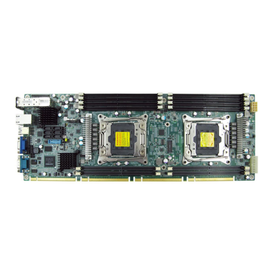
Chapter 1� Product Features Phoenix User Manual Chapter 1. Product Features This section describes the hardware specifications and features of the Phoenix motherboard. The fundamental components of the Phoenix severboard are provided below. 1�1 Component Phoenix Serverboard Socket R3 (FCLGA2011-3) to support Intel ®... -
Page 9: 1.2 Specifications
Phoenix User Manual Chapter 1. Product Features 1.2 Specifications Two Intel® Xeon® Processors E5-2600 v3 and Processor Built-in SATA controller with RAID support on SATA Support v4 product family Intel® C612 Chipset 145W CPU TDP Aspeed AST2400 Advanced PCIe Graphics &... -
Page 10: 1�3 Feature
Chapter 1. Product Features 1�3 Feature The Phoenix server board integrates two Intel® Xeon® Processors E5-2600 v3 and v4 processors and 12 DDR4 DIMM to offer support for greater capacity, durability, and efficiency for our customers. Featuring the Intel® Xeon® Processor E5-2600 v3 and... -
Page 11: Chapter 2. Hardware Setup
Chapter 2. Hardware Setup Phoenix User Manual Chapter 2. Hardware Setup 2�1 Processor 2�1�1 Removing the CPU Step 1 Remove the heatsink. The heatsink is attached to the server board or processor socket with captive fasteners. Use a #2 Phillips* screwdriver to loosen the screws x 4 located on the heatsink corners diagonally using the following procedure (1a) to (1b). - Page 12 Phoenix User Manual Chapter 2. Hardware Setup Step 2 Unlatch the CPU Load Plate by following procedures (2a) to (2b). (2a) Push the lever handle labeled “OPEN 1st” (see letter A) down and towards the CPU socket. Rotate the lever handle upward.
-
Page 13: Installing The Cpu
Phoenix User Manual Chapter 2. Hardware Setup 2�1�2 Installing the CPU CAUTION Check your processor type before installing. You may damage the sever board if you install an inappropriate processor for your server. CAUTION ESD protection and handling procedures reduce the risk of electrostatic discharge (ESD) damage to the processor. - Page 14 Phoenix User Manual Chapter 2. Hardware Setup Step 2 Remove the socket cover from the load plate. NOTE Do not throw away the socket cover. It can be re-used when the processor need to be removed at any time in the future.
- Page 15 Phoenix User Manual Chapter 2. Hardware Setup Step 5 Installing the heatsink on top of the processor. CAUTION The processor heat sink for CPU1 and CPU2 are different. FXXXCA91X91HS is for CPU1, while FXXEA91X91HS2 is for CPU2. Mislocating the heat sink will cause serious damage.
-
Page 16: 2�2 System Memory
Phoenix User Manual Chapter 2. Hardware Setup 2�2 System Memory 2�2�1 Placement This server board supports up to twelve DDR4 1333/1600/1866/2133 Registered ECC SDRAM(RDIMM) / Load-Reduced DIMM (LRDIMM). JDIMMG0 JDIMMG0 JDIMMA0 JDIMMA0 JDIMMG1 JDIMMG1 JDIMMA1 JDIMMA1 JDIMMH0 JDIMMH0 JDIMMB0 JDIMMB0... -
Page 17: Dimm Population
Phoenix User Manual Chapter 2. Hardware Setup 2�2�2 DIMM Population JDIMMG0 JDIMMA0 JDIMMG1 JDIMMA1 JDIMMH0 JDIMMB0 JDIMMH1 JDIMMB1 DIMM Numbers DIMM ARRANGMENT CPU1 CPU0 CPU1 CPU0 2 DIMMs JDIMM_G0 JDIMM_A0 JDIMMF0 JDIMMC0 JDIMME0 JDIMMD0 JDIMMG0 JDIMMA0 JDIMMG1 JDIMMA1 JDIMMB0 JDIMMH0... - Page 18 Phoenix User Manual Chapter 2. Hardware Setup JDIMMG0 JDIMMA0 JDIMMG1 JDIMMA1 JDIMMB0 JDIMMH0 JDIMMB1 JDIMMH1 CPU1 CPU0 JDIMM_G0 JDIMM_A0 8 DIMMs JDIMM_H0 JDIMM_B0 CPU1 CPU0 JDIMM_F0 JDIMM_D0 JDIMM_E0 JDIMM_C0 JDIMMF0 JDIMMD0 JDIMME0 JDIMMC0 JDIMMG0 JDIMMA0 JDIMMG1 JDIMMA1 JDIMMH0 JDIMMB0 JDIMMH1...
-
Page 19: Installation
Phoenix User Manual Chapter 2. Hardware Setup 2�2�3 Installation Step 1 Unlock the DIMM socket by pressing the retaining clips outward. Step 2 Insert the memory module into the slot. Make sure that the DIMM notch is accurately positioned. DIMM notch... -
Page 20: Chapter 3� Motherboard Settings
Chapter 3� Motherboard Settings Phoenix User Manual Chapter 3. Motherboard Settings 3�1 Block Diagram... -
Page 21: 3�2 Content List
Phoenix User Manual Chapter 3. Motherboard Settings 3�2 Content List Connector and Header Location Connector and Header Location Power Supply JPWR2 16 BMC I2C10 Header JBMC_I2C10 Connector (2x4 pin) 2 Power Supply JPWR1 17 USB 3.0 Type A Port Connector (2x8 pin) -
Page 22: 3�3 Placement
Phoenix User Manual Chapter 3. Motherboard Settings 3�3 Placement... -
Page 23: 3�4 Connector
Phoenix User Manual Chapter 3. Motherboard Settings 3�4 Connector 1 Power Connector (JPWR2) 2 Power Connector (JPWR1) 3 Intruder Header (JINTRUDER) 4 LCM Header (JLCM) 8 COM Port (JCOM4) 6 BMC GPIO Header (JBMC_GPIO) 9 VGA Header (JVGA_INT) 10 IPMB Header... - Page 24 Phoenix User Manual Chapter 3. Motherboard Settings 25 Front Panel Header (JFRNT) I2C8SDA +5V_AUX I2C8SCL FAN8_TACH PSU_SMBDAT_SUS FAN7_TACH PSU_SMBCLK_SUS FAN6_TACH I2C5SDA FAN5_TACH I2C5SCL FAN4_TACH FAN3_TACH FAN12_TACH FAN2_TACH FAN11_TACH FAN1_TACH FAN10_TACH PWM4 FAN9_TACH PWM3 PWM6 PWM2 PWM5 PWM1 LAN4_TRAFFIC +3.3V_DUAL LAN3_TRAFFIC +3.3V_DUAL...
-
Page 25: 3�5 Jumper
Phoenix User Manual Chapter 3. Motherboard Settings 3�5 Jumper A System PG Lock Jumper (JPG_LOCK) B BMC Disable Jumper (JBMC_DIS) Setting Setting JBMC_DIS JPG_LOCK Short Disable Short Lock Open Normal (Default) Open Normal (Default) C NTB Jumper (JNTB) D ME Force Recovery Mode Jumper(J1) -
Page 26: 3�6 Led Indicator
Phoenix User Manual Chapter 3. Motherboard Settings 3�6 LED Indicator UID LED Heart Beat LED RSMRST PG LED SYS PG LED On (Blinking) BMC activity detected. Heart Beat BMC is not active. System power good ready. SYS PG System power good is not ready. -
Page 27: Chapter 4. Bios Configuration Settings
Chapter 4. BIOS Configuration Settings Phoenix User Manual Chapter 4. BIOS Configuration Settings NOTE When quiet boot is enabled, OEM logo wll be displayed instead of post messages. Press ESC to run the setup procedure. There will be a message “Entering SETUP” displayed on the diagnostics screen. - Page 28 Phoenix User Manual Chapter 4. BIOS Configuration Settings Identify the BIOS Version. Load Optimal Default setting.
- Page 29 Phoenix User Manual Chapter 4. BIOS Configuration Settings Save the setting and exit the BIOS setup utility.
-
Page 30: 4�1 Bios Update
Phoenix User Manual Chapter 4. BIOS Configuration Settings 4�1 BIOS Update To identify the current BIOS version, please check the BIOS setup. There are two methods to update the latest BIOS. 1. Update by Messiash Flash utility during POST. 2. Update by AMI AFUDOS utility under DOS environment Update by Messiash Flash utility during POST 1. - Page 31 Phoenix User Manual Chapter 4. BIOS Configuration Settings Update BIOS by INSYDE H2OFFT-D utility under DOS environment If you need to update Flash in the DOS environment, please use H2OFFT-D utility. To use this utility, you must include the flash.bat , H2OFFT-D.exe, and bin file in the same folder.
-
Page 32: Chapter 5. Bmc Configuration Settings
Chapter 5. BMC Configuration Settings Phoenix User Manual Chapter 5. BMC Configuration Settings Insert the Ethernet LAN cable into the BMC LAN port. There are two methods to setup the BMC IP: BMC management port 5�1 Method 1 (Use the BIOS Setup) Step 1 Enter BIOS SETUPServer MgmtBMC network configuration... - Page 33 Phoenix User Manual Chapter 5. BMC Configuration Settings...
- Page 34 Phoenix User Manual Chapter 5. BMC Configuration Settings Step 2 Type in the IP address. Configure the static IP. Step 3 Type in the subnet mask address.
-
Page 35: 5�2 Method 2 (Use A Dos Tool - Syscheck)
Phoenix User Manual Chapter 5. BMC Configuration Settings 5�2 Method 2 (Use a Dos Tool - Syscheck) Step 1 Type in "sc –lanset." Step 2 Modify the IP setting. NOTE Type 1 for selecting Static IP Mode for type 2 for selecting DHCP Mode. - Page 36 Phoenix User Manual Chapter 5. BMC Configuration Settings Step 3 Type in the IP address. Step 4 Type in the submask address. The IP address below is an example using a default IP setting. The user is allowed to change the IP address for individaul purposes.
- Page 37 Phoenix User Manual Chapter 5. BMC Configuration Settings Step 5 Complete BMC IP configuration. NOTE Type SC.EXE-LANGET command to obtain BMC IP and MAC address.
-
Page 38: 5�3 Login
Phoenix User Manual Chapter 5. BMC Configuration Settings 5�3 Login The IP address below is an example using default IP setting. User is allowed to change the IP address for individual purposes. 1. Open the browser then type default BMC IP address: 192.168.22.22 2. - Page 39 Phoenix User Manual Chapter 5. BMC Configuration Settings Default User Name and Password UserName: admin Password: admin NOTE The default user name and password are in lower-case characters. When you log in using the user name and password, you can receive full adminstratice rights. It is advised to change your password once you login.
-
Page 40: 5�4 Web Gui
Phoenix User Manual Chapter 5. BMC Configuration Settings 5�4 Web GUI 5�4�1 Menu Bar Click to select the options of the menu bar. Menu Description The Dashboard page gives the overall information about the status of a Dashboard device. The FRU Information page displays the details for FRU devices in the FRU Information system. -
Page 41: User Information And Quick Button
Phoenix User Manual Chapter 5. BMC Configuration Settings 5�4�2 User Information and Quick Button The user information and quick access buttons are located at the top right corner. It displays the logged-in user, his/her privilege and the four quick buttons allowing you to perform different functions. -
Page 42: Dashboard
Phoenix User Manual Chapter 5. BMC Configuration Settings 5�4�3 Dashboard The Dashboard page gives the overall information about the status of a device. To open the Dashboard page, click Dashboard from the menu bar. A sample screenshot of the Dashboard page is shown below. -
Page 43: Field Replaceable Unit(Fru)
Phoenix User Manual Chapter 5. BMC Configuration Settings 5�4�4 Field Replaceable Unit(FRU) The FRU Information Page displays the BMC FRU file information. The information displayed in this page is Basic Information, Common Header Information, Chassis Information, Board Information and Product Information of the FRU device. -
Page 44: Auto Video Recording
Phoenix User Manual Chapter 5. BMC Configuration Settings 5�4�5 Auto Video Recording The Auto Video Recording consists of the following. • Triggers Configuration • Recorded Video 5.4.6.1 Triggers Configuration This page is used to configure the triggers for various events, which can be used by the KVM server to perform auto video recording feature. -
Page 45: Chapter 6� Technical Support
Chapter 6� Technical Support Taiwain, Global Headquarters South California, United States Address: No. 152, Section 4, Address: 21808 Garcia Lane Linghang N� Rd, Dayuan District, City of Industry, CA 91789, Taoyuan City 337, Taiwan United States Tel: +886-3-433-9188 Toll free: +7-4997019998 Fax: +886-3-287-1818 Tel: +1-909-895-8989 Sales Email: sales@aicipc.com.tw...
Need help?
Do you have a question about the Phoenix and is the answer not in the manual?
Questions and answers