Table of Contents
Advertisement
Quick Links
Advertisement
Table of Contents

Related Manuals for AIC apollo


Summary of Contents for AIC apollo
- Page 1 Apollo Server MotherBoard User's Manual UM_Apollo_v.1_120716...
-
Page 2: Table Of Contents
CONTENTS Safety Information �������������������������������������������������������������������������� i About This User Manual ����������������������������������������������������������������� ii Chapter 1� Product Introduction ������������������������������������������������ 1 1�1 General Information ���������������������������������������������������������������������������1 1.2 Specifications �������������������������������������������������������������������������������������2 Chapter 2� Hardware Installation ����������������������������������������������� 3 2�1 System Memory ����������������������������������������������������������������������������������3 Chapter 3� Motherboard Settings ����������������������������������������������� 6 3�1 Motherboard block diagram ������������������������������������������������������������6 3�2 Motherboard Layout ��������������������������������������������������������������������������7 3�3 Motherboard Content List ������������������������������������������������������������������8... - Page 3 5�4�7 Maintenance Group ����������������������������������������������������������������144 5�4�8 Firmware Update ���������������������������������������������������������������������153 Chapter 6� Technical Support������������������������������������������������� 159 contents...
- Page 4 Copyright © 2016 AIC, Inc� All Rights Reserved� This document contains proprietary information about AIC products and is not to be disclosed or used except in accordance with applicable agreements.
-
Page 5: Safety Information
Safety Information When installing, operating, or performing maintenance on this equipment, the following safety precautions should always be observed in order to reduce the risk of fire, electric shock, and personal injury. Read and understand all instructions. • Observe warnings and instructions marked on the product. •... -
Page 6: About This User Manual
About This User Manual This document provides a detailed description of the Motherboard including: • General Features of the Product • Hardware Setup • Motherboard Settings • BIOS Configuration and Settings • BMC Configuration and Settings Product features and specifications are subject to change without notice. CAUTION : risk of explosion if battery is replaced by an incorrect type. -
Page 7: Chapter 1� Product Introduction
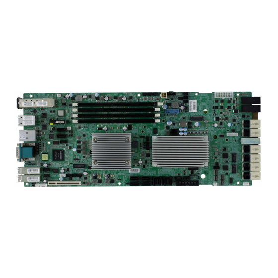
Chapter 1 Product Introduction Chapter 1� Product Introduction 1�1 General Information Apollo, a server grade mother board supports Intel® Xeon® processor D-1500 Product series. Apollo User's Manual... -
Page 8: Chapter 1 Product Introduction
• Baseboard Management Controller IPMI Information (2) 2 x DMI (by Intel I210 Gigabit MAC/PHY) • Intelligent Platform Interface 2.0 (IPMI 2.0) (3) Intel NTB (PCIE port3a) x8 • iKVM, Media Redirection, IPMI over LAN, Serial over LAN Apollo User's Manual... -
Page 9: Chapter 2� Hardware Installation
SAS EXP HEART BIT LED JCOM1 PCIE HOT-PLUG SMB JSGPIO JBMC_GPIO JBMC_I2C1 LED7:RSMRST PG LED LED8:SYSTEM PG LED SATA3 SATA5 TP15 JEXP_RST SAS IOC ICE SAS IOC SGPIO SAS EXP SGPIO SATA6 SATA4 JBMC_RST JBMC_DP JNTB JUSB_MB JINTRUDER JLCM JFRNT_SSI Apollo User's Manual... -
Page 10: Chapter 2 Hardware Installation
2.1.1 Populate DIMMs in the following order: DIMM Number DIMM arrangement JDIMM_B1 1 DIMMs JDIMM_B1 JCPU0 JDIMM_A1 JDIMM_B1 2 DIMMs JDIMM_A1 JDIMM_B1 JCPU0 JDIMM_A1 JDIMM_B0 JDIMM_B1 JDIMM_A1 JDIMM_B1 3 DIMMs JDIMM_B0 JCPU0 JDIMM_A0 JDIMM_A1 JDIMM_B0 JDIMM_B1 4 DIMMs JDIMM_A1 JDIMM_B1 JDIMM_A0 JDIMM_B0 JCPU0 Apollo User's Manual... - Page 11 2.1.2 DIMM Installation Procedure Unlock a DIMM socket by pressing the retaining clips outward. Insert module vertically and press down until it snaps into place. Note: DIMM notch and socket bump must align as shown. DIMM notch Apollo User's Manual...
-
Page 12: Chapter 3� Motherboard Settings
Flash UART0 S25FL256SAGMFI001 Debug port @12Gb/s @12Gb/s ICE0 NVSRAM I210AT PCI Express x 1 Debug port CY14V101LA-BA25 Flash @5GT/s S29GL128S11TFIV2 SAS3X36 (SAS3X28) SFF-8644 SAS PHY x4 SAS PHY x20 SFF-8644 SAS PHY x4 SAS PHY x4 Option Apollo User's Manual... -
Page 13: 3�2 Motherboard Layout
LED7:RSMRST PG LED LED8:SYSTEM PG LED SATA5 SATA3 TP15 JEXP_RST SAS IOC ICE SAS IOC SGPIO SAS EXP SGPIO SATA6 SATA4 JBMC_RST JNTB JUSB_MB JBMC_DP JNTB JINTRUDER JLCM JFRNT_SSI JFRNT_SSI JUSB_MB JLCM JINTRUDER JBMC_GPIO JBMC_DP JSGPIO JBMC_I2C1 Apollo User's Manual... -
Page 14: 3�3 Motherboard Content List
SAS IOC ERROR System PG Lock JPG_LOCK 58 SAS IOC ACTIVITY BMC Buzzer JBUZZER BIOS Recovery SAS IOC ICE Mode ME Force SAS IOC SGPIO Recovery Mode Flash Descriptor SAS EXP SKU Security override Reboot(Watch SATA Power Apollo User's Manual Dog) -
Page 15: 3�4 Internal Connectors/Jumpers
78 76 74 72 70 68 74 74 72 70 68 68 R362 77 75 77 75 77 75 73 71 69 73 71 69 LED1 JBMC_I2C10 JBMC_DIS UID LED JCOM1 PCIE HOT-PLUG SMB JSGPIO JBMC_GPIO JBMC_I2C1 JBMC_RST JBMC_DP JLCM JINTRUDER JBMC_DP Apollo User's Manual... - Page 16 Internal Connectors/Jumpers JBMC_I2C10 JBUZZER JVGA_INT BMC BUZZER- DACROA I2C10SDA DACGOA I2C10SCL DDC_DATAO DACBOA AHSYNCO DVO_5V AVSYNCO DDC_CLKO JINTRUDER JLCM JBMC_DP JCOM1 JLCM JINTRUDER Setting ShortC ase Open OFFE nable( Default) JCOM1 JBMC_I2C10 JBMC_GPIO JCOM4 I2C10SDA I2C10SCL JSGPIO JDOM_PWR Apollo User's Manual...
- Page 17 Inlet Thermal Sensor JPG_LOCK JSPI_BIOS JPG_LOCK SAS EXP MDIO SAS EXP HEART BIT LED LED7:RSMRST PG LED LED8:SYSTEM PG LED SATA3 SATA5 TP15 JEXP_RST SAS IOC ICE SAS IOC SGPIO SAS EXP SGPIO SATA4 SATA6 JUSB_MB JFRNT_SSI JUSB_MB JFRNT_SSI Apollo User's Manual...
- Page 18 Chapter 3 Motherboard Setting Internal Connectors/Jumpers JPWR2 JPMBUS J8 J9 J10 +12V J14 J15 J16 JPWR2 JPWR1 JVBATT_12C JUSB_MB JUSB_MB JVBATT_I2C JFRNT_SSI JFRNT_SSI Apollo User's Manual...
- Page 19 7 7 5 BROADWELL-DE SAS EXP MDIO SAS EXP HEART BIT LED LED7:RSMRST PG LED LED8:SYSTEM PG LED SATA5 SATA3 TP15 JEXP_RST SAS IOC ICE SAS IOC SGPIO SAS EXP SGPIO SATA4 SATA6 JNTB JNTB JUSB_MB JFRNT_SSI Apollo User's Manual...
- Page 20 Chapter 3 Motherboard Setting Internal Connectors/Jumpers JSPKR JNGFF Apollo User's Manual...
- Page 21 Chapter 3 Motherboard Setting Internal Connectors/Jumpers JLPC_DP CLK_33M_DP80 PCH_LFRAME_N PCH_GPIO61 RST_PLTRST_N PCH_SERIRQ PCH_LPC_LAD3 PCH_LPC_LAD2 PCH_LPC_LAD1 +3.3V PCH_LPC_LAD0 Apollo User's Manual...
- Page 22 Chapter 3 Motherboard Setting Internal Connectors/Jumpers JPCH_GPIO JUSB_INT JSPI_BIOS JPCH_GPIO HOLD# +3.3V PCH_GPIO9 PCH_GPIO21 PCH_GPIO10 PCH_GPIO27 Apollo User's Manual...
-
Page 23: 3�5 Leds
No critical failures detected Green (Blinking) Disk activity detected Hard Disk No disk activity detected Green (Blinking) NIC1 activity detected NIC 1 NIC is not active Green (Blinking) NIC2 activity detected NIC 2 NIC is not active Apollo User's Manual... - Page 24 Status LED 1G : Orange, 100M: Green 10M/No NIC 4 (Left) connect: Off Yellow PHY 1 (Right) (Blinking) 100M: Yellow 10M/No connect: Off Green PHY1 activity detected PHY 1 (Left) PHY1 is not active, LAN cable no connect Apollo User's Manual...
- Page 25 Blue(Blinking) SAS EXP activity detected SAS EXP HEART BIT LED SAS EXP not activity detected Synchronize Multi-EXP Blue(Blinking) activity detected SAS EXP SYNC BLINK Synchronize Multi-EXP not activity detected Blue(Blinking) NGFF activity detected NGFF ACTIVITY LED NGFF not activity detected Apollo User's Manual...
-
Page 26: Chapter 4. Bios Configuration And Settings
Press ESC to run the setup procedure. There will be a message “Entering SETUP” displayed on the diagnostics screen. Caution: For the official released version, the last digit of the BIOS Version must end in an "0." Apollo User's Manual... - Page 27 Chapter 4 BIOS Configuration and Settings Identify the BIOS Version Load Optimal Default setting Save the setting and exit the BIOS setup utility. Apollo User's Manual...
-
Page 28: 4�1 Updating Bios
Chapter 4 BIOS Configuration and Settings 4�1 Updating BIOS Important Notes: To identify the current BIOS version, please check out on BIOS setup. Apollo User's Manual... - Page 29 H2OFFT-D utility. To use this utility, you must include the flash.bat , H2OFFT-D.exe, and bin file in the same folder. Please follow the instructions to update whole flash part: Execute flash.bat to update Flash in the DOS environment. Reboot system. Apollo User's Manual...
-
Page 30: Chapter 5. Bmc Configuration And Settings
Chapter 5. BMC Configuration and Settings Insert Ethernet LAN cable into the BMC LAN port. There are two methods to setup BMC IP: BMC management port 5�1 Method 1 (Use the BIOS setup) • BIOS SETUPServer MgmtBMC network configurationConfiguration Address sourceStatic Apollo User's Manual... - Page 31 Chapter 5 BMC Configuration and Settings 2. Input IP address. Set static IP. Apollo User's Manual...
- Page 32 Chapter 5 BMC Configuration and Settings 3. Input subnet mask address. Apollo User's Manual...
-
Page 33: 5�2 Method 2 (Use A Dos Tool - Syscheck)
5�2 Method 2 (Use a Dos tool - Syscheck) 1. Type : sc –lanset 2. Modify IP setting Note: type 1 for selecting static IP mode or type 2 for selecting DHCP mode. 3. Input IP address Apollo User's Manual... - Page 34 Below IP address is an example using a default IP setting. User is allowed to change the IP address for realistic use. 5. Finish BMC IP configuration. Note: Type sc.exe –langet command to obtain BMC IP and MAC address. Apollo User's Manual...
-
Page 35: 5�3 Bmc Web-Browser-Megarac® Gui Overview
It has a low learning curve because it uses standard Internet browsers. • This chapter allows you to become familiar with the MegaRAC® GUI’s various functions. Each function is described in detail. note : Your MegaRAC® GUI may not exactly match this document. Apollo User's Manual... -
Page 36: 5�3�1 Supported Browsers
Chapter 5 BMC Configuration and Settings 5.3.1 Supported Browsers Operating System Browser Version Linux Windows MAC OS Firefox 2.0 and above Yes-Default Internet 7 and above Yes-Default Explorer Safari 3.0 and above Yes-Default Chrome 2.0 and above Opera 9.64 and above Apollo User's Manual... -
Page 37: 5�3�2 Supported
• Ubuntu 9.10 LTS – 64 • Ubuntu 8.10 -32 • Ubuntu 8.10 -64 • OpenSuse 11.2 -32 • OpenSuse 11.2 -64 • FC 9 – 32 and above • FC 9 – 64 and above • MAC -32 • MAC-64 Apollo User's Manual... -
Page 38: 5�3�3 Login The Web Page
Forgot Password: If you forget your password, you can generate a new one using this link. Enter the username, click on Forgot Password link. This will send the newly generated password to the configured Email-ID for the user. Apollo User's Manual... - Page 39 Enable javascript for this site: The icon indicates whether the javascript setting is enabled in browser. Enable cookies for this site: The icon indicates whether the cookies setting are enabled in browser. note : Cookies must be enabled in order to access the website. Apollo User's Manual...
- Page 40 Once you login to the application, it is recommended not to use the following options. -Refresh button of the browser -Refresh menu of the browser -Back and Forward options of the browser -F5 on the keyboard -Backspace on the keyboard Apollo User's Manual...
-
Page 41: 5�4 Using Megarac Sp
The user information and quick buttons are located at the top right of the MegaRAC® GUI. A screenshot of the logged-in user information is shown below. The logged-in user information shows the logged-in user, his/her privilege and the four quick buttons allows you to perform the following functions. Apollo User's Manual... - Page 42 Refresh: Click the icon to reload the current page. Print: Click the icon take the print out of the current page. Logout: Click the icon to log out of the MegaRAC® GUI. HELP: Click to view the help page. Apollo User's Manual...
-
Page 43: 5�4�1 Dashboard
• IPv4 Address: The IPv4 address of the device (could be static or DHCP). • V6 Network Mode: The v6 network mode of the device which could be either disable, static or DHCP. • IPv6 Address: The IPv6 address of the device. Apollo User's Manual... - Page 44 A graphical representation of all events incurred by various sensors and occupied/available space in logs can be viewed. If you click on the color-coded rectangle in the Legend for the chart, you can view a list of those specific events only. Apollo User's Manual...
-
Page 45: 5�4�2 Field Replaceable Unit(Fru)
To open the FRU Information Page, click FRU Information from the menu bar. Select a FRU Device ID from the Basic Information section to view the details of the selected device. A screenshot of FRU Information page is given below. Apollo User's Manual... - Page 46 Product Information • Product Information Area Format Version • Language • Manufacturer Name • Product Name • Product Part Number • Product Version • Product Serial Number • Asset Tag • FRU File ID • Product Extra Apollo User's Manual...
-
Page 47: 5�4�3 Server Health Group
To open the Sensor readings page, click Server Health→Sensor Readings from the menu. Click on a record to show more information about that particular sensor, including thresholds and a graphical representation of all associated events. A screenshot of Sensor Readings page is given below. Apollo User's Manual... - Page 48 - going high, Upper Critical - going low, Upper Critical - going high, Upper Non-recoverable - going low, Upper Non-recoverable - going high. A graphical view of these events (Number of event logs vs. Thresholds) can be viewed as shown in the Sensor Readings Page screenshot. Apollo User's Manual...
- Page 49 The result will be dis- played a s a line graph i n the widget. The session will not expire, until the widgets gets a live data o f the last widget that i s kept opened. Apollo User's Manual...
- Page 50 BMC owned sensors. SPX firmware UI has been taken care is displaying the Node Manager related sensors properly. Like- wise the customer utilities also should be taken care in displaying the sensor reading of Node Manager using BMC related commands. Apollo User's Manual...
- Page 51 Filter By: Filtering can be done with the sensors mentioned in the list. Note : Once the Event Log category and Filter type are selected, the list of events will be displayed with the Event ID, Time Stamp, Sensor Type, Sensor Name and Description. Apollo User's Manual...
- Page 52 3. Select either BMC Timezone or Client Timezone. The events will displayed based on the selected time zone value. 4. To clear all events from the list, click Clear All Event Logs button. 5. To save all the existing event logs, click Save Event Logs button. Apollo User's Manual...
- Page 53 To view System Log, click the System Log tab to view all system events. Entries can be filtered based on their levels like Alert, Critical, Error, Notification, Warning, Debug, Emergency and Information. To view Audit Log, click the Audit Log label to view all audit events for this device. Apollo User's Manual...
- Page 54 Service can be configured under Configuration Services KVM. -Depending o n the PRJ configuration i n MDS, the image will be saved as JPEG or raw data. A sample screenshot of Event Log page is shown below. Apollo User's Manual...
-
Page 55: 5.4.4 Configuration Group
Chapter 5 BMC Configuration and Settings 5.4.4 Configuration Group This group of pages allows you to access various configuration settings. A screenshot of Configuration Group menu is shown below. Apollo User's Manual... - Page 56 To view the page, you must be at least a User and to modify or add a group, you must be an Administrator. To open Active Directory Settings page, click Configuration→ Active Directory Settings from the menu bar. A sample screenshot of Active Directory Settings page is shown below. Apollo User's Manual...
- Page 57 Group Privilege: The level of privilege to assign to this role group. Add Role Group: To add a new role group to the device. Modify role Group: To modify the existing role group. Delete Role Group: To delete an existing Role Group. Apollo User's Manual...
- Page 58 - Password must b e at least 6 character long and will not allow more than 127 characters. - White space is not allowed. Apollo User's Manual...
- Page 59 9. In the Active Directory Settings Page, select a blank row and click Add Role Group or alternatively double click on the blank row to open the Add Role group Page as shown in the screenshot below. Apollo User's Manual...
- Page 60 Modify Role Group or double click the row that you wish to modify. 17.Make the necessary changes and click Save. To Delete a Role Group 18.In the Advanced Directory Settings Page, select the row that you wish to delete. 19.Click Delete Role Group. Apollo User's Manual...
- Page 61 The DNS Server settings page is used to manage the DNS settings of a device. To open DNS Server Settings page, click Configuration→DNS from the menu bar. A sample screenshot of DNS Server Settings page is shown below. Apollo User's Manual...
- Page 62 Domain Name: It displays the domain name of the device. If the Domain setting is chosen as Manual, then specify the domain name of the device. If you chose Automatic, the Domain Name cannot be configured as it will be done automatically. The field will be disabled. Apollo User's Manual...
- Page 63 DNS settings. • Check the option Register BMC to register with this DNS settings. • Choose the option Direct Dynamic DNS to register with direct dynamic DNS or choose DHCP Client FQDN to register throughDHCP server. Apollo User's Manual...
- Page 64 • Enter the DNS Server address. 7. In DNS Server1, DNS Server2 and DNS Server3, enter the server addresses to be configured for the BMC. 8. Click Save to save the entries. 9. Click Reset to reset the entries. Apollo User's Manual...
- Page 65 Event Log Policy for Event Log. Save: To save the configured settings. Reset: To reset the modified changes. Procedure: Choose either Enable Linear Event Log Policy or Enable Circular Event Log Policy and click Save to save the changes. Apollo User's Manual...
- Page 66 To open Images Redirection page, click Configuration→Images Redirection from the menu bar. A sample screenshot of Images Redirection page is shown below. The fields of Images Redirection page are explained below. • Local Media • Remote Media Apollo User's Manual...
- Page 67 U s e r n a m e , P a s s w o r d a n d D o m a i n N a m e : I f s h a r e T y p e i s Samba(CIFS), then user credentials to authenticate the server. Save: To save the settings. Cancel: To cancel the modifications and return to Image list. Apollo User's Manual...
- Page 68 Image to replace the existing image. Alternatively, double click on the configured slot. 5� Browse the image File and click Replace 6. To delete an image, select a record and click Delete Image to delete the selected image. Apollo User's Manual...
- Page 69 Advanced Settings and make sure Remote Media Support option is enabled. If not, disable Local Media Redirection and then enable Remote Media Redirection. Note : The Start Redirection button i s active only for VMedia enabled users. Apollo User's Manual...
- Page 70 Image to replace the existing image. Alternatively, double click on the configured slot. 5. To delete an image, select the desired image to be deleted and click Delete Image. Note : Redirection needs to be stopped to replace or delete the image Apollo User's Manual...
- Page 71 T o o p e n L D A P / E - D I R E C T O R Y S e t t i n g s p a g e , c l i c k Configuration→LDAP/E-Directory from the menu bar. A sample screenshot of LDAP/E-Directory Settings page is shown below. Apollo User's Manual...
- Page 72 Each Number ranges from 0 to 255. First Number must not be 0. Supports IPv4 Address format and IPv6 Address format. 4. Specify the LDAP Port in the Port field. Note : Default Port is 389. For Secure connection, default port is 636. Apollo User's Manual...
- Page 73 To add a new Role Group 10.In the LDAP/E-Directory Settings Page, select a blank row and click Add Role Group or alternatively double click on the blank row to open the Add Role group Page as shown in the screenshot below. Apollo User's Manual...
- Page 74 Modify Role Group or double click the row that you wish to modify. 18.Make the necessary changes and click Save. To Delete a Role Group 19.In the LDAP/E-Directory Settings Page, select the row that you wish to delete. 20.Click Delete Role Group. Apollo User's Manual...
- Page 75 Upload license Key window as shown below. 2. Enter the License Key. 3. Click Add to add the license key. 4. Click Cancel to go back to the License page. 5. The added license can be seen in the grid. Apollo User's Manual...
- Page 76 Relative Mode: Relative mode sends the calculated relative mouse position displacement to the server. Other Mode: To have the calculated displacement from the local mouse in the center position sent to the server. Save: To save the changes made. Reset: To Reset the modified changes. Apollo User's Manual...
- Page 77 Applicable for all Linux versions, versions less than RHEL6, and ver- sions less than FC14. • Set Mode to Other Mode Note : Recommended for SLES-11 OS Installation 2. Click Save button to save the changes made. 3. Click Reset to reset the modified changes. Apollo User's Manual...
- Page 78 2. Choose the Channel Number to be configured for the selected Interface name. 3. Choose the Package ID to be configured for the selected Interface name. 4. Click Save to save the current changes. 5. Click Reset to reset the modified changes. Apollo User's Manual...
- Page 79 IPv4 address, Subnet Mask and Default Gateway to be configured to the device. Note : -IP Address made of 4 numbers separated by dots as in “xxx.xxx.xxx.xxx”. -Each Number ranges from 0 to 255. -First Number must not be 0. Apollo User's Manual...
- Page 80 3. In IPv4 Configuration, enable Use DHCP to Obtain an IP address automatically to dynamically configure IPv4 address using DHCP. 4. If the field is disabled, enter the IPv4 Address, Subnet Mask and Default Gateway in the respective fields. Apollo User's Manual...
- Page 81 8. In VLAN Configuration, if you wish to enable the VLAN settings, check Enable. 9. Enter the VLAN ID in the specified field. 10.Enter the VLAN Priority in the specified field. 11.Click Save to save the entries. 12.Click Reset if you want to reset the modified changes. Apollo User's Manual...
- Page 82 The fields of Network Bonding page are explained below. Network Bonding: To enable or disable network bonding for network interfaces. Bonding Mode: This field displays the Network bonding mode. Note : This field cannot be configured. Apollo User's Manual...
- Page 83 The Default Interface can be selected only if the Network Bonding is enabled. 2. Check the Enable option to enable the Auto Configuration. 3. Click Save to save the configuration. 4. Click Reset to reset the configuration. Apollo User's Manual...
- Page 84 Link Speed: Link speed will list all the supported capabilities of the network interface. It can be 10/100/1000 Mbps. Duplex Mode: Duplex Mode could be either Half Duplex or Full Duplex. Save: To save the settings. Reset: To reset the modified changes Apollo User's Manual...
- Page 85 The Link Speed and Duplex Mode will be active only when Auto Nego- tiation is OFF. 3. Select the Link Speed from the drop-down list. 4. Select the Duplex Mode from the drop-down list. 5. Click Save to save the configuration. 6. Click Reset to reset the configuration. Apollo User's Manual...
- Page 86 Invalid Password. S o it i s always treated a s Invalid Password error. For Invalid Password error PAM will not try other Authenti- cation Methods. So it is recommended to keep AD in the last loca- tion in PAM order. Apollo User's Manual...
- Page 87 2. Select the required PAM module and click button to move the module one step after the existing module. 3. Click Save to save any changes made. 4. Click Reset to reset the modified changes. Apollo User's Manual...
- Page 88 In MegaRAC GUI, the PEF Management is used to configure the following • Event Filter • Alert Policy • LAN Destination To open PEF Management Settings page, click Configuration→PEF from the menu bar. Each tab is explained below. Apollo User's Manual...
- Page 89 Sensor Name: To choose the particular sensor from the sensor list. Add: To add the new event filter entry and return to Event filter list. Modify: To modify the existing entries. Delete: To delete the configured event filter. Apollo User's Manual...
- Page 90 • PEF ID displays the ID for configured PEF entry (read-only). • In Filter Configuration, check the box to enable the PEF settings. • In Event Severity, select any one of the Event severity from the list. Apollo User's Manual...
- Page 91 • Select the sensor type of sensor that will trigger the event filter action. • In the sensor name field, choose the particular sensor from the sensor list. • Choose event option to be either All Events or Sensor Specific Events. Apollo User's Manual...
- Page 92 13.In the Event filter list, select the configured slot and click Modify or alternatively double click the configured slot to modify the existing event filter entry. 14.In the Event filter list, click Delete to delete the existing filter. Apollo User's Manual...
- Page 93 Channel Number: To choose a particular channel from the available channel list. Destination Selector: To choose a particular destination from the configured destination list. Note : LAN Destination h as t o be c onfigured - under Configuration Apollo User's Manual Destination.
- Page 94 10.In the Alert String Key field, choose any one value that is used to look up the Alert String to send for this Alert Policy entry. 11.Click Add to save the new alert policy and return to Alert Policy list. Apollo User's Manual...
- Page 95 Modify or alternatively double click on the configured slot that you wish to modify. 14.In the Modify Alert Policy Entry Page, make the necessary changes and click Modify. 15.In the Alert Policy list, to delete a configuration, select the slot and click Delete. Apollo User's Manual...
- Page 96 Send Test Alert: To send sample alert to configured destination. Note : Test alert can sent only with enabled S MTP configuration. SMTP support can be enabled under Configuration SMTP. Apollo User's Manual...
- Page 97 7. In the Subject field, enter the subject. 8. In the Message field, enter the message. 9. Click Add to save the new LAN destination and return to LAN destination list. 10. Click Cancel to cancel the modification and return to LAN destination list. Apollo User's Manual...
- Page 98 @def IS_MEDIUM_ERROR(x) @brief checks if error type is MEDIUM_ERROR_FLAG #define IS_MEDIUM_ERROR(x)(((x)>>8) == MEDIUM_ERROR_FLAG ) @def IS_IPMI_ERROR(x) @brief checks if error type is IPMI_ERROR_FLAG #define IS_IPMI_ERROR(x)(((x)>>8) == IPMI_ERROR_FLAG ) @def IS_RMCP_RAKP_ERROR(x) @brief checks if error type is IPMI_ERROR_FLAG Apollo User's Manual...
- Page 99 #define LIBIPMI_MEDIUM_E_WSA_INIT_FAILURE 0x04 #define LIBIPMI_MEDIUM_E_INVALID_SOCKET 0x05 #define LIBIPMI_MEDIUM_E_TIMED_OUT 0x06 #define LIBIPMI_MEDIUM_E_UNSUPPORTED 0x07 #define LIBIPMI_MEDIUM_E_OS_UNSUPPORTED 0x08 #define LIBIPMI_MEDIUM_E_INVALID_PARAMS 0x09 #define LIBIPMI_MEDIUM_E_INVALID_DATA 0x0A #define LIBIPMI_MEDIUM_E_TIMED_OUT_ON_SEND 0x0B /* Session related errors */ #define LIBIPMI_SESSION_E_EXPIRED 0x10 #define LIBIPMI_SESSION_E_RECONNECT_FAILURE 0x11 #define LIBIPMI_SESSION_E_HANDSHAKE_NOT_RECVD 0x12 Apollo User's Manual...
- Page 100 0x55 /* Session Establishment Errors */ #define LIBIPMI_E_INVALID_OPEN_SESSION_RESPONSE 0x60 #define LIBIPMI_E_INVALID_RAKP_MESSAGE_2 0x61 #define LIBIPMI_E_AUTH_ALG_UNSUPPORTED 0x62 #define LIBIPMI_E_INTEGRITY_ALG_UNSUPPORTED 0x63 #define LIBIPMI_E_CONFIDENTIALITY_ALG_UNSUPPORTED 0x64 #define LIBIPMI_E_AUTH_CODE_INVALID 0x65 #define LIBIPMI_E_INVALID_RAKP_MESSAGE_4 0x66 #define LIBIPMI_E_INVALID_HMAC_SIK 0x67 /* Highlevel function errors */ #define LIBIPMI_E_INVALID_USER_ID Apollo User's Manual...
- Page 101 #define LIBIPMI_E_IPMB_LOCK_ACCESS_FAILED 0x87 #define LIBIPMI_E_IPMB_COMM_FAILURE 0x88 #define LIBIPMI_E_IPMB_UNKNOWN_ERROR 0x89 #define LIBIPMI_E_IPMB_REQ_BUFF_TOO_BIG 0x8A #define LIBIPMI_E_IPMB_RES_BUFF_TOO_BIG 0x8B /* Last RMCP+/RAKP satus code */ #define LAST_RMCP_RAKP_STATUS_CODE (SC_NO_CIPHER_SUITE_ MATCH) /* Error Codes for FRU*/ #define FRU_INVALID_HEADER_VERSION 0x8C #define FRU_INVALID_AREA 0x8D #endif Apollo User's Manual...
- Page 102 - First Number must not be 0. Secret: The Authentication Secret for RADIUS server. Note : -This field will not allow more than 31 characters. - Secret must be at least 4 characters long. - White space is not allowed. Apollo User's Manual...
- Page 103 5. Enter the authentication secret for RADIUS Server in the Secret field. 6. In the Extended Privileges, check the required options, • KVM • VMedia. 7. Click Save to save the entered details. 8. Click Reset to reset the entered details. Apollo User's Manual...
- Page 104 Media Encryption: Enable/Disable encryption on Media data for the next redirection session. Note : This option is disabled if Single Port is enabled. Virtual Media Attach Mode: Two types of VM attach mode are available: Attach - Immediately attaches Virtual Media to the server upon Apollo User's Manual...
- Page 105 If we choose more than 2 virtual Hard disks, then the RHEL5 host displays only two hard disks in “Computer” window. When we redi- rect third hard disk, the third hard disk will appear in “Computer” window Apollo User's Manual...
- Page 106 SSH service will not support non secure port. If single port feature is enabled, KVM, CD Media, FD Media and HD Media ports cannot be edited. Secure Port: Used to configure secure port number for the service. • Web default port is 443 Apollo User's Manual...
- Page 107 Whenever t he c onfiguration i s modified, the service w ill be r estarted automatically. User has to close the existing opened session for the ser- vice if needed. 2. This opens the Modify Service screen as shown in the screenshot below. Apollo User's Manual...
- Page 108 8. Enter the timeout value in the Timeout field. Note : The values in the Maximum Sessions field cannot be modified. 9. Click Modify to save the entered changes and return to the Services Page. 10. Click Cancel to exit. Apollo User's Manual...
- Page 109 - Space, special characters are not allowed. Primary SMTP Server: Lists the Primary SMTP Server configuration. SMTP Support: To enable/disable SMTP support for the BMC. Server Address: The ‘IP address’ of the SMTP Server. It is a mandatory field. Apollo User's Manual...
- Page 110 It is an optional field. If the Primary SMTP server is not working fine, then it tries with Secondary SMTP Server configuration. Save: To save the new SMTP server configuration. Reset: To reset the modified changes. Apollo User's Manual...
- Page 111 10. Enable the check box SMTP Server requires Authentication if you want to authenticate SMTP Server. 11. Enter your User name and Password in the respective fields. 12. Click Save to save the entered details. 13. Click Reset to update the entered details. Apollo User's Manual...
- Page 112 New Certificate: Certificate file should be of pem type Current Privacy Key: Current privacy key information will be displayed (read-only). New Privacy Key: Privacy key file should be of pem type Upload: To upload the SSL certificate and privacy key into the BMC. Apollo User's Manual...
- Page 113 State or Province(ST): State or Province of the organization (mandatory). • Maximum length of 64 characters. • Special characters ‘#’ and ‘$’ are not allowed. Country(C): Country code of the organization (mandatory). • Only two characters are allowed. • Special characters are not allowed. Apollo User's Manual...
- Page 114 • Valid From • Valid To Issued To: This section display the information about the certificate issuer. • Common Name(CN) • Organization(O) • Organization Unit(OU) • City or Locality(L) • State or Province(ST) • Country(C) • Email Address Apollo User's Manual...
- Page 115 MegaRAC® SP’s IP address here> -For example, if your MegaRAC® SP’s IP address is 192.168.0.30, enter the following: https://192.168.0.30 -Please note t he <s> after <http>.You must accept t he certificate before you are able to access your Generic MegaRAC® SP. Apollo User's Manual...
- Page 116 - When log information exceeds the file size, the old log informa- tion i s automatically m oved t o back u p files b ased o n the rotate count value. If rotate count is zero, then old log information gets Apollo User's Manual cleared permanently.
- Page 117 Steps to configure the remote server to enable syslogging Note : This example uses FC13 as the remote machine to log syslog. On FC machine, disable the following lines for UDP in /etc/rsyslog. conf. 1. MODLOAD imudp 2. UDPSERVER 514 Apollo User's Manual...
- Page 118 Click the IP Address tab. A sample screenshot of IP address tab is shown below. The fields of System Firewall - IP Address tab are explained below. IP/IP Address Range : Lists all the IP Address or Range of IP Addresses Apollo User's Manual...
- Page 119 IP or IP Range. 4. Click Save to save the changes made else click Cancel to go back to the previous screen. 5. To delete an IP address or a range of IP addresses, select the slot and click Delete. Apollo User's Manual...
- Page 120 3. Select the Protocol to be either TCP or UDP. 4. Select the Port Setting to be either Block or Allow. Port Settings are used to determine the rule whether block or allow from the configured Port or Port Range. Apollo User's Manual...
- Page 121 Add User: To add a new user. Modify User: To modify an existing user. Delete User: To delete an existing user. Procedure Note : The Free slots are denoted by “~” in all columns for the slot. Apollo User's Manual...
- Page 122 6. In the Extended Privileges, check the required options, • KVM • VMedia. 7. Check the SNMP Status check box to enable SNMP access for the user. Note : Password field is mandatory, if SNMP Status is enabled. Apollo User's Manual...
- Page 123 Modify an existing User 15. Select an existing user from the list and click Modify User or alternatively double click on the configured slot. This opens the Modify User screen as shown in the screenshot below. Apollo User's Manual...
- Page 124 PMC File” for the list of reserved users. Important: Reserved Users: There are certain reserved users w hich cannot be added as BMC Users. The list of reserved users are given below, -sysadmin -daemon -sshd -ntp -stunnel4 Apollo User's Manual...
- Page 125 Procedure 1. Select the number of Floppy devices, CD/DVD devices and Harddisk devices from the drop-down list Note : Maximum of t wo d evices can be a dded i n Floppy, C D/DVD and Harddisk Apollo User's Manual drives.
- Page 126 Unmounting d evice will make t he d river d isconnect device w hen using “ Auto Attach”. H ence, w hen unmounting o ne USB key, the other USB key will be disconnected and then reconnected. For more details refer “Media” Apollo User's Manual...
-
Page 127: 5�4�5 Remote Control
The Remote Control consists of the following menu items. Console Redirection Server Power Control Java SOL A sample screenshot of the Remote Control menu is given below. A detailed description of the menu items are given below. Apollo User's Manual... - Page 128 • FC 9 - 64 • FC 10 - 32 • FC 10 - 64 • FC 12 - 32 • FC 12 - 64 • FC 13 - 32 • FC 13 - 64 • FC 14 - 32 Apollo User's Manual...
- Page 129 1. Open the Dashboard Page and in Remote control section, click Launch for Java Console. 2. Open Remote Control>Console Redirection Page and click Java Console. This will download the .jnlp file from BMC. To open the .jnlp file, use Apollo User's Manual...
- Page 130 The Console Redirection menu bar consists of the following menu items. • Video • Keyboard • Mouse • Options • Media • Keyboard Layout • Video Record • Power • Active Users • Help A detailed explanation of these menu items are given below. Apollo User's Manual...
- Page 131 Full Screen: This option is used to view the Console Redirection in full screen mode (Maximize). This menu is enabled only when both the client and host resolution are same. Exit: This option is used to exit the console redirection screen. Note : ** Specific to Hornet Apollo User's Manual...
- Page 132 The configured key events are saved in the BMC. Full Keyboard Support: Enable this option to provide full keyboard support. This option is used to trigger the Ctrl and Alt key directly to host from the physical keyboard. Apollo User's Manual...
- Page 133 Band width (Except Hornet): The Bandwidth Usage option allows you to adjust the bandwidth. You can select one of the following: Auto Detect - This option is used to detect the network bandwidth usage of the BMC automatically. Apollo User's Manual...
- Page 134 This option can be configured from PRJ in MDS. Send IPMI Command – This option opens the IPMI Command dialog. Enter the raw IPMI command in Hexadecimal field as Hexadecimal value and click Send. The Response will be displayed as shown in the screenshot below. Apollo User's Manual...
- Page 135 Request Full Permission - Partially Permitted sessions can use this option to request the Full permission from the existing full permitted session. Note : This menu option is available only for partially privileged session and Full permission ses¬sions will not have this option in the menu. Apollo User's Manual...
- Page 136 Floppy Key Media: This menu item can be used to start or stop the redirection of a physical floppy drive and floppy image types such as img. Note : Floppy Redirection is not an available feature on all versions of the Mega- RAC® SPs. Apollo User's Manual...
- Page 137 For Linux client, fixed hard drive is redirected only as Read Mode. It is not Write mode supported. For USB key image redirection, support FAT 16, FAT 32 and NTFS. SPX Stack Media redirection supports only Basic Hard disk Redirec- tion. Apollo User's Manual...
- Page 138 We have list of the language support in SPX JViewer. Note : Soft k eyboard i s applicable only for JViewer Application not f or o ther application in the client system. Apollo User's Manual...
- Page 139 5. Click OK to save the entries and return to the Console Redirection screen. 6. Click Cancel if you don’t wish to save the entries. 7. In the Console Redirection window, click Video Record→Start Record. 8. Record the process. 9. To stop the recording, click Video Record→Stop Record. Apollo User's Manual...
- Page 140 The lower right of Console Redirection windows displays all the quick buttons. These quick buttons helps you to perform these functions by just clicking them. Note : This option is available only when you launch the Java Console. Apollo User's Manual...
- Page 141 “immediate shutdown” action will be triggered in host If the icon is in red color server status is “power off” . Click the button to “power on” the host. This quick button displays the available hotkeys. Apollo User's Manual...
- Page 142 Select an action and click Perform Action to proceed with the selected action. Note : You w ill be asked t o confirm your c hoice. U pon confirmation, t he c om- mand will be executed and you will be informed of the status. Apollo User's Manual...
- Page 143 For more details on SOL, click SOL. To open Java SOL page, click Remote Control→Java SOL from the menu bar. A sample screenshot of Java SOL page is shown below. Procedure: 1. Click the Java SOL button to open the Java SOL window. Apollo User's Manual...
- Page 144 2. Enter the BMC IP address, User Name and Password in the respective fields. 3. Select the Volatile-Bit-Rate and Non-Volatile-Bit-Rate from the drop down lists. 4. Click Connect to open the SOL redirection window as shown in the screenshot below. Apollo User's Manual...
-
Page 145: 5�4�6 Auto Video Recording
Chapter 5 BMC Configuration and Settings 5.4.6 Auto Video Recording The Auto Video Recording consists of the following. • Triggers Configuration • Recorded Video A sample screenshot of the Auto Video Recording menu is given below. Apollo User's Manual... - Page 146 • LPC Reset Event Save: To save any changes made. Reset: To reset the modified changes. Procedure: 1. Check the events to be enabled. 2. To set particular Date and Time Event, check the option Particular Date and Time Event. Apollo User's Manual...
- Page 147 • Choose the month, day and year from the Date field • Enter the Time in hh:mm:ss format in the respective fields. 3. Click Save to save the changes. 4. Click Reset to reset the changes made Apollo User's Manual...
- Page 148 File Information – Day, date and time of video upload Play Video – To play the selected video Download – To download the selected video Delete – To delete the selected video. Procedure: 1. Click Advanced Settings. a. Check Enable to enable the Remote Video Support. Apollo User's Manual...
- Page 149 BMC reboot. The Play V ideo a nd Download video buttons are active only for the KVM enabled users. If t he Recorded V ideo F iles are stored i n RAM, then those v ideo recordings will not be persistent upon BMC Reboot. Apollo User's Manual...
- Page 150 5.4.7 Maintenance Group This group of pages allows you to do maintenance tasks on the device. The menu contains the following items: • Preserve Configuration • Restore Configuration • System Administrator A detailed description is given below. Apollo User's Manual...
- Page 151 Check All: To check the entire configuration list. Uncheck All: To uncheck the entire configuration list. Save: To save any changes made. Note : This configuration is used by Restore Factory Defaults process. Reset: To reset the modified changes. Apollo User's Manual...
- Page 152 This file is used to store the Hostname of the BMC. hostname�conf: This file is used to configure the host name creation method Manual/Automatic for the BMC. Vlaninterfaces: This file helps to enable the vlan interface for the Apollo User's Manual...
- Page 153 This file is to configure the active interface for the specified bond interface. This file depends on bond.conf. hosts: This file is used to store the host name to map the IP address. Apollo User's Manual...
- Page 154 This file contains the keyword argument pairs of configurations such as Adderss family, Accept Env, Allow, users, authorized key files etc. ssh_host_dsa_key , ssh_host_rsa_key : These files contain the private parts of the host keys. ssh_host_dsa_key�pub, ssh_host_rsa_key�pub: These files contain the Apollo User's Manual...
- Page 155 Linux. passwd: This file contains the user login information for the Linux system shadow: This file contains the encrypted password information for the clients. ldap�conf: This file contains the ldap server configuration details such Apollo User's Manual...
- Page 156 Check All or Uncheck All buttons respectively. 2. Click Save to save the changes. 3. Click Reset to reset the selection. Apollo User's Manual...
- Page 157 1. Click Enter Preserve Configuration to redirect to Preserve Configuration page, which is used to preserve the particular configuration not to be overwritten by the default configuration. 2. Click Restore Configuration to restore the factory defaults of the device firmware. Apollo User's Manual...
- Page 158 This action enables the password fields. 3. Enter the new password in the Password field. 4. Re-enter the password in the Confirm Password field. 5. Click Save to save the changes. 6. Click Reset to reset the changes. Apollo User's Manual...
- Page 159 Chapter 5 BMC Configuration and Settings 5.4.8 Firmware Update This group of pages allows you to do the following. The menu contains the following items: • Firmware Update • Images Transfer Protocol • Dual Image Configuration A detailed description is given below. Apollo User's Manual...
- Page 160 MegaRAC® card before you can perform any o ther types o f opera- tions. To open Firmware Update page, click Firmware Update→Firmware Update from the menu bar. A sample screenshot of Firmware Update Page is shown below. Apollo User's Manual...
- Page 161 A file upload pop-up will be displayed for http/https but in the case of tftp files, the file is automatically uploaded displaying the status of upload. • Browse and select the Firmware image to flash and click Upload. Apollo User's Manual...
- Page 162 You c an n ow f ollow the instructions p resented i n the subsequent p ages to successfully update the card’s firmware. The device will reset if update is canceled. The device will also reset upon successful completion of firm- ware update. Apollo User's Manual...
- Page 163 1. Select the Protocol Type from the drop-down list. 2. If the protocol selected is TFTP, enter the IP address of the server in the Server Address field. 3. Enter the Source Path in the given field. 4. Enter the Retry Count value. Apollo User's Manual...
- Page 164 Chapter 5 BMC Configuration and Settings 5. Click Save to save the changes. 6. Click Reset to reset the entered values. Apollo User's Manual...
- Page 165 Chapter 6� Technical Support www�aicipc�com • TAIWAN Tel: +886 3 433 9188 Fax: +886 3 287 1818 Email : sales@aicipc�com�tw • CHINA Tel: +86�21�54961421, +86�21�54961422 Fax: Extension: 608 Email Technical Support: support@aicipc�com • AMERICA - West coast Tel: +1�909�895�8989 Fax: +1.909.895.8999 Email : sales@aicipc�com •...
Need help?
Do you have a question about the apollo and is the answer not in the manual?
Questions and answers