Table of Contents
Advertisement
Quick Links
Download this manual
See also:
User Manual
Advertisement
Table of Contents

Related Manuals for AIC PHOENIX


Summary of Contents for AIC PHOENIX
- Page 1 Phoenix Server MotherBoard User’s Manual UM_Phoenix_v.2_101915...
-
Page 2: Table Of Contents
Contents Contents ................................i About This User Manual ............................. ii Chapter 1................................1 1.1 General Information ..........................1 1.2 Specifications ............................1 Chapter 2................................3 2.1 Central Processing Unit (CPU) ........................ 3 Chapter 3................................. 12 3.1 Motherboard block diagram ........................ 12 3.2 Motherboard Layout ........................... -
Page 3: Safety Information
Safety Information When installing, operating, or performing maintenance on this equipment, basic safety precautions, as listed below, should always be followed to reduce the risk of fire, electric shock, and personal injuries. Read and understand all instructions. Observe warnings and instructions marked on the product. ... -
Page 4: About This User Manual
About This User Manual This document provides a detailed description of the Phoenix including: The General Features of the Product Motherboard Settings BIOS Configuration and Settings BMC Configuration and Settings ... -
Page 5: Chapter 1
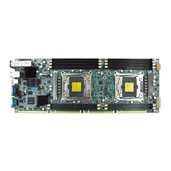
Chapter 1. Product Introduction 1.1 General Information Phoenix, a server grade mother board supports two Intel Xeon processor E5-2600 ® ® V3 series. 1.2 Specifications Dimensions (with chassis ears/protrusions) mm : 424.2 x 157.5 W x D inches : 16.7 x 6.2... - Page 6 • SPI (Serial Peripheral Interface) FLASH Interface • EFI 2.3 BIOS • ACPI 1.0/2.0/3.0 • PXE 2.0 • WOL BIOS Features • AC loss recovery • IPMI KCS interface • SMBIOS 2.0 • Serial console redirection On-Board Devices Built-in SATA controller with RAID support on Intel C610 series chipset ®...
-
Page 7: Chapter 2
Chapter 2. Hardware Setup 2.1 Central Processing Unit (CPU) 2.1.1 Removing the Processor Heatsink The heatsink is attached to the server board or processor socket with captive fasteners. Using a #2 Phillips* screwdriver, loosen the four screws located on the heatsink corners in a diagonal manner using the following procedure: ˙Using a #2 Phillips* screwdriver, start with screw 1 and loosen it by giving it two rotations and stop (see letter A). - Page 8 2.1.2 Installing the Processor 2.1.2.1 Unlatch the CPU Load Plate Push the lever handle labeled “OPEN 1st” (see letter A) down and toward the CPU socket. Rotate the lever handle up. Repeat the steps for the second lever handle (see letter B).
- Page 9 2.1.2.2 Lift open the Load Plate •Rotate the right lever handle down until it releases the Load Plate (see letter A). •While holding down the lever handle, with your other hand, lift open the Load Plate (see letter B).
- Page 10 2.1.2.3 Install the Processor •Remove the processor from its package. •Carefully remove the protective cover from the bottom side of the CPU, taking care not to touch any CPU contacts (see letter A). •Orient the processor with the socket so that the processor cutouts match the four orientation posts on the socket (see letter B).
- Page 11 2.1.2.4 Remove the Socket Cover. Remove the socket cover from the load plate by pressing it out. 2.1.2.5 Close the Load Plate. Carefully lower the load plate down over the processor. 2.1.2.6 Lock down the Load Plate Push down on the locking lever on the CLOSE 1st side (see letter A). Slide the tip of the lever under the notch in the load plate (see letter B).
- Page 12 2.1.3 Installing the Processor Heatsink If present, remove the protective film covering the Thermal Interface Material on the bottom side of the heatsink (see letter A). • Align the heatsink fins to the front and back of the chassis for correct airflow. The airflow goes from front-to-back of the chassis (see letter B).
- Page 13 2.1.4 Removing the Processor...
- Page 14 2.2 System Memory This server board supports up to twelve DDR4 1333/1600/1866/2133 Registered ECC SDRAM(RDIMM) / Load-Reduced DIMM (LRDIMM). Populate DIMMs in the following order: DIMM DIMM arrangement Numbers CPU1 JCPU0 2 DIMMs JDIMM_G0 JDIMM_A0 CPU1 JCPU0 4 DIMMs JDIMM_G0 JDIMM_A0 JDIMM_H0 JDIMM_B0...
- Page 15 DIMM DIMM arrangement Numbers CPU1 JCPU0 JDIMM_G0 JDIMM_A0 8 DIMMs JDIMM_H0 JDIMM_B0 JDIMM_F0 JDIMM_D0 JDIMM_E0 JDIMM_C0 CPU1 JCPU0 JDIMM_G0 JDIMM_A0 JDIMM_G1 JDIMM_A1 10 DIMMs JDIMM_H0 JDIMM_B0 JDIMM_F0 JDIMM_D0 JDIMM_E0 JDIMM_C0 CPU1 JCPU0 JDIMM_G0 JDIMM_A0 JDIMM_G1 JDIMM_A1 12 DIMMs JDIMM_H0 JDIMM_B0 JDIMM_H1 JDIMM_B1 JDIMM_F0...
-
Page 16: Chapter 3
Chapter 3. Motherboard Settings This section describes the jumpers, internal connectors, and internal LEDs setting on Phoenix motherboard. Motherboard layout and important jumper settings are listed as below. 3.1 Motherboard block diagram 3.2 Motherboard Layout... -
Page 17: Motherboard Content List
3.3 Motherboard Content List Connectors Location Connectors Location SFP+ Port (Dual Port) SFP+ BMC_I2C10 JBMC_I2C10 Ethernet (Dual Port) RJ45 BMC IPMI JBMC_I2C1 USB Port (Dual Port) USB3.0 Battery Socket JBAT COM Port Intruder JINTRUDER VGA Port PMBUS JPMBUS Power Supply (2x7 pin) JPWR1 SPI ROM Socket JSPI... -
Page 18: Internal Connectors/Jumpers
3.4 Internal Connectors/Jumpers Connectors/Jumpers Description A1. GND B1.SW_PWR_BTN# A2. GND B2.SW_RST_BTN# A3. GND B3. FP_NMI_BTN A4. GND B4. UID_SW_IN_N A5. UIDLED_OUT# B5. +3.3V_DUAL A6. HD_LED B6. +3.3V A7. SYS_HEALTH# B7. STD_LED A8. GND B8. PWR_LED A9. LAN1_TRAFFIC B9. +3.3V A10. LAN2 TRAFFIC# B10. - Page 19 3. GND 10. +12V 4. GND 11. +12V 5. GND 12. +12V 6. GND 13. +5V_AUX 7. PS_ON# 14. POWER OK 1.GND 5. +12V 2. GND 6. +12V JPWR2 Power Supply 3. GND 7. +12V 4. GND 8. +12V...
- Page 20 Internal Connectors/Jumpers (Continued) Connectors/Jumpers Description System PG Lock Open/Normal (Default) JPG_LOCK (Jumper) Short/Lock Open/Normal (Default) ME Force Recovery Mode(Jumper) Short/ME Recovery Mode Open/Disable (Default) Watch dog(Jumper) Short/Enable Open/Normal (Default) BIOS Recovery Mode (Jumper) Short/BIOS Recovery Mode Flash Descriptor Open/Normal (Default) Security override Short/Flash Security override...
- Page 21 Open/Normal (Default) BMC Reset Setting JBMC_RST (Jumper) Short/Reset BMC Open/Normal (Default) Setting JBMC_DIS (Jumper) Short/Disable 1. P3V3_VBAT Pin1-2 close/Normal(Default) CMOS Jump Setting JCMOS 2. RST_RTCRST_N Pin2-3 close/Clear CMOS (Jumper) 3. GND 1. GND 4. PCH_SLOAD 2. PCH_SDATAOUT0 5. +3.3V JSGPIO JSGPIO 3.
- Page 22 Internal Connectors/Jumpers (Continued) Jumpers Description 1. GND 2. DACROA 3. DACGOA 4. NC 5. DDC_DATAO 6. GND 7. GND 8. DACBOA JVGA_INT 9. NC 10. AHSYNCO 11. AVSYNCO 12. DVO_5V 13. GND 14. GND 15. GND 16. DDC_CLKO 1.GND 2. CLK_33M_DP80 3.
-
Page 23: Leds
5. I2C9SCL 6. BMC_GPY0 1.SCOM2_T3OUT 3.GND JBMC_DP BMC debug Port 2.SCOM2_R4IN 1. DSRB 2. DCDB 3. RTSB 4. RXDB JCOM4 Front COM Header 5. CTSB 6. TXDB 7. RIB 8. DTRB 9. NC 10. GND 1. PWR_BTN 2. RST_BTN JLCM 3. - Page 24 3.5.2 Rear chassis LEDs NIC 1 Yellow 1G link detected, activity detected (82599) / (Right Upward Triangle) (Blinking) Activity detected (XL710) Green 10G link detected, activity detected (82599) / NIC 1 (Left Upward Triangle) (Blinking) 1/10G link detected (XL710) NIC 2 Yellow 1G link detected, activity detected (82599) / (Right Downward Triangle)
-
Page 25: Chapter4
Chapter4. BIOS Configuration and Settings 1. Press ESC to run the setup procedure. 2. Choose the SCU to enter the Setup menu. - Page 26 3. Identify the BIOS Version 4. Load Optimal Default setting...
-
Page 27: Updating Bios
5. Save the setting and exit the BIOS setup utility. 4.1 Updating BIOS Important Notes: To identify the current BIOS version, please check out on BIOS setup. - Page 28 Update by Insyde H2offt-d utility under DOS environment If you need to update Flash in the DOS environment, please use H2offt-d utility. To use this utility, you must include the flash.bat , H2offt-d.exe, and bin file in the same folder. Please follow the instructions to update whole flash part: 1.
-
Page 29: Chapter 5
Chapter 5. BMC Configuration and Settings Insert Ethernet LAN cable into the BMC LAN port. There are two methods to setup BMC IP: BMC management port 5.1 Method 1 (Use the BIOS setup) BIOS SETUP Advanced H2O IPMI configuration BMC Configuration IPv4 source ... - Page 31 Input IP address. Set static IP. Input subnet mask address.
-
Page 32: Method 2 (Use A Dos Tool - Syscheck)
5.2 Method 2 (Use a Dos tool - Syscheck) Type : sc –lanset. Modify IP setting. Input IP address. - Page 33 Input submask address. Below IP address is an example using a default IP setting. User is allowed to change the IP address for realistic use. Finish BMC IP configuration.
-
Page 34: Connect To Bmc
5.3 Connect to BMC Below IP address is an example using default IP setting. User is allowed to change the IP address for realistic use. Open the browser then type default BMC IP address: 192.168.22.22 Use the default user name and password for first-time login to BMC WEB GUI. Field: Default UserName:... - Page 35 Information of firmware. Server Health - Sensor Readings:...
- Page 36 Configuration Please refer to AIC BMC User Guide for more information on AIC BMC. Mouse Mode setting: For Windows OS environment, set mode to absolute. For Linux OS environment, set mode to relative.
- Page 37 Remote Control: Environmental setting: Press “ALT+C” for local and remote OS mouse control switching.
-
Page 38: Updating Bmc Firmware
3. Execute a.bat batch file to update the BMC firmware Example: A:>cd SB301C01 A:\ SB301C01>a.bat This is just an example. The latest BMC firmware version is available from the FAE or AIC website. After update BMC firmware, please power off and then power on system. -
Page 39: Chapter 6
Chapter 6. Technical Support www.aicipc.com TAIWAN Tel: +886 3 433 9188 Fax: +886 3 287 1818 Email Technical Support: sales@aicipc.com.tw CHINA Tel: +021.54961421, +021.54961422 Fax: Extension: 608 Email Technical Support: support@aicipc.com AMERICA - West coast Tel: +1.909.895.8989 Fax: +1.909.895.8999 Email Technical Support: sales@aicipc.com.tw...
Need help?
Do you have a question about the PHOENIX and is the answer not in the manual?
Questions and answers