Table of Contents
Advertisement
Quick Links
Download this manual
See also:
User Manual
Advertisement
Table of Contents

Related Manuals for AIC Lynx


Summary of Contents for AIC Lynx
- Page 1 Lynx Server MotherBoard User's Manual UM_Lynx_v1.1_110617...
-
Page 2: Table Of Contents
CONTENTS Safety Information �������������������������������������������������������������������������� i About This User Manual ����������������������������������������������������������������� ii Chapter 1� Product Introduction ������������������������������������������������ 1 1�1 General Information ���������������������������������������������������������������������������1 1.2 Specifications �������������������������������������������������������������������������������������2 Chapter 2� Hardware Installation ����������������������������������������������� 3 2�1 Central Processing Unit (CPU) �����������������������������������������������������������3 2�2 HFI Carrier Card for Host Fabric Interface (HFI) Supported ������������7 2�3 System Memory ����������������������������������������������������������������������������������8 Chapter 3�... - Page 3 Copyright © 2017 AIC, Inc� All Rights Reserved� This document contains proprietary information about AIC products and is not to be disclosed or used except in accordance with applicable agreements.
-
Page 4: Safety Information
Safety Information When installing, operating, or performing maintenance on this equipment, the following safety precautions should always be observed in order to reduce the risk of fire, electric shock, and personal injury. Read and understand all instructions. • Observe warnings and instructions marked on the product. •... -
Page 5: About This User Manual
About This User Manual This document provides a detailed description of the Motherboard including: • General Features of the Product • Hardware Setup • Motherboard Settings • BIOS Configuration and Settings • BMC Configuration and Settings Product features and specifications are subject to change without notice. CAUTION : risk of explosion if battery is replaced by an incorrect type. -
Page 6: Chapter 1� Product Introduction
Chapter 1 Product Introduction Chapter 1� Product Introduction 1�1 General Information Lynx, a server grade mother board supports Xeon Processor Scalable Family Lynx User's Manual... -
Page 7: Chapter 1 Product Introduction
• Up to 3TB 3DS ECC RDIMM/LRDIMM Controller Mezzanine extension • Realtek RTL8201E for BMC dedicate management port 2 x AIC Max I/O™ support: Aspeed AST2500 Advanced PCIe Graphics & PCIe Gen3 total 96 lanes; Remote Management Processor (each 48 lanes from CPU0 & CPU1) Graphics •... -
Page 8: Chapter 2� Hardware Installation
2.1.1 Processor Support The server board includes two processor sockets (LGA3647) and can support one or two of the Intel® Xeon® Processor Scalable Family, with a Thermal Design Power (TDP) of up to 165W on selected models. Lynx User's Manual... - Page 9 2.1.2 Processor Heat Sink Module and Processor Socket Assembly Each processor socket of the server board is pre-assembled with a loading mechanism that allows to secure the placement of the Processor Heat Sink Module (PHM) to the server board as shown below. Non-Fabric Processor Assembly Lynx User's Manual...
- Page 10 Processor Heat Sink Module (PHM) Sub-Assembly Heat Sink Heat Sink Non Fabric Fabric Processor Clip Processor Clip Non Fabric Fabric Processor Processor Processor Heatsink Module (PHM) Bottom View for the Non-Fabric Processor Bottom View for the Fabric Processor Lynx User's Manual...
- Page 11 Once the PHM is seated over the processor socket assembly, the four heat sink torque screws must be tightened in order as shown below. Processor Heat Sink – Top View with Screw Tightening Order Lynx User's Manual...
-
Page 12: 2�2 Hfi Carrier Card For Host Fabric Interface (Hfi) Supported
HFI card. JHFI1 (Host Fabric Interface) Sideband Cable 3. Connect the HFI connector on the HFI cable to the onboard JHFI1 header. • HFI Drawing example� • Cards & Cables are not included in the range of supply� Lynx User's Manual... -
Page 13: 2�3 System Memory
2�3 System Memory This server board supports up to twenty-four DDR4 2400/2666 Registered ECC SDRAM(RDIMM) / Load-Reduced DIMM (LRDIMM). JDIMMJ1 JDIMMJ0 JDIMMK1 JDIMMK0 JDIMML1 JDIMML0 JDIMMC0 JDIMMC1 JDIMMB0 JDIMMB1 JDIMMA0 JDIMMA1 JDIMMD1 JDIMMD0 JDIMME1 JDIMME0 JDIMMF1 JDIMMF0 Lynx User's Manual... - Page 14 JDIMMK0 JDIMMF1 JDIMML1 JDIMMF0 JDIMML0 CPU1 CPU0 JDIMMI1 JDIMMC1 JDIMM_I0 JDIMM_C0 JDIMMH1 JDIMMB1 JDIMMG1 JDIMMA1 JDIMM_H0 JDIMM_B0 8 DIMMs CPU1 CPU1 CPU0 CPU0 JDIMM_G0 JDIMM_A0 JDIMMD1 JDIMMJ1 JDIMMJ0 JDIMMD0 JDIMME1 JDIMMK1 JDIMM_L0 JDIMM_F0 JDIMME0 JDIMMK0 JDIMMF1 JDIMML1 Lynx User's Manual...
- Page 15 JDIMMK1 JDIMM_L0 JDIMM_F0 JDIMMF1 JDIMML1 CPU1 CPU0 JDIMM_I0 JDIMM_C0 JDIMM_I1 JDIMM_C1 JDIMM_H0 JDIMM_B0 JDIMM_H1 JDIMM_B1 18 DIMMs CPU1 CPU1 CPU0 CPU0 JDIMM_G0 JDIMM_A0 JDIMM_G1 JDIMM_A1 JDIMMJ1 JDIMMD1 JDIMM_J0 JDIMM_D0 JDIMME1 JDIMMK1 JDIMM_K0 JDIMM_E0 JDIMMF1 JDIMML1 JDIMM_L0 JDIMM_F0 Lynx User's Manual...
- Page 16 JDIMM_E0 JDIMM_L1 JDIMM_F1 JDIMM_L0 JDIMM_F0 CPU1 CPU0 JDIMM_I0 JDIMM_C0 JDIMM_I1 JDIMM_C1 JDIMM_H0 JDIMM_B0 JDIMM_H1 JDIMM_B1 JDIMM_G0 JDIMM_A0 24 DIMMs JDIMM_G1 JDIMM_A1 CPU1 CPU1 CPU0 CPU0 JDIMM_J1 JDIMM_D1 JDIMM_J0 JDIMM_D0 JDIMM_K1 JDIMM_E1 JDIMM_K0 JDIMM_E0 JDIMM_L1 JDIMM_F1 JDIMM_L0 JDIMM_F0 Lynx User's Manual...
- Page 17 2.3.2 DIMM Installation Procedure Unlock a DIMM socket by pressing the retaining clips outward. Insert module vertically and press down until it snaps into place. Note: DIMM notch and socket bump must align as shown. DIMM notch Lynx User's Manual...
-
Page 18: Chapter 3� Motherboard Settings
PCI Express x 16 Port3a(IOU2) Placement PCI Express x 16 Port2a(IOU1) PCI Express x 16 Port3a(IOU2) Port2a(IOU1) Port1a(IOU0) Port1a(IOU0) PCIEX48 Riser Slot CPU0 CPU1 CONN B PCI Express x 8 Port3c(IOU2) CONN C CONN A PCI Express x 8 Port3a(IOU2) Lynx User's Manual... -
Page 19: 3�2 Motherboard Layout
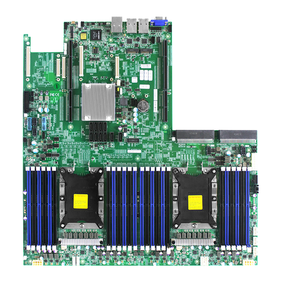
Chapter 3 Motherboard Setting 3�2 Motherboard Layout JPWR6 JPWR3 JCOM4 JDIMMJ1 JDIMMJ0 JVGA_INT JDIMMK1 JPCIE_HP JDIMMK0 JPWR_AUX JDIMML1 JDIMML0 JNGFF2 JDIMMC0 JNGFF1 JDIMMC1 JDIMMB0 JDIMMB1 JDIMMA0 AVSYNCO JDIMMA1 JBMC_I2C10 JBMC_GPIO1 JBMC_I2C1 JCOM1 JDIMMD1 JDIMMD0 JDIMME1 JDIMME0 JDIMMF1 JDIMMF0 Lynx User's Manual... -
Page 20: 3�3 Motherboard Content List
FAN 2B CONN VROC Key JRAID_KEY OCP CONN (PCIE) CN1、CN2 PCIE Hot-Plug SMB JPCIE_HP Riser CONN CN3、CN4 VRM SMB JSMB_VR Riser CONN CN8、CN9 OCuLink CONN JSYS_EXT OCP CONN (PCIE) CN5、CN6 OCP CONN NTB Configurations JNTB (KR Function) Lynx User's Manual... -
Page 21: 3�4 Internal Connectors/Jumpers
JDIMMC0 JNGFF1 JDIMMC1 JDIMMB0 JDIMMB1 JDIMMA0 AVSYNCO JDIMMA1 JBMC_I2C10 JBMC_GPIO1 JBMC_I2C1 JCOM1 JDIMMD1 JDIMMD0 JDIMME1 JDIMME0 JDIMMF1 JDIMMF0 JVGA_INT JCOM4 JPWR_AUX DACROA N.C. DACGOA DDC_DATAO +3.3V_DUAL +3.3V_DUAL DACBOA +3.3V +3.3V AHSYNCO N.C. +12V +12V DVO_5V AVSYNCO DDC_CLKO Lynx User's Manual... - Page 22 N.C. NGFF_ALERT# NGFF2_SATA_B-_RX_DP_2 NGFF_SDA NGFF2_SATA_B+_RX_DN_2 NGFF_SCL NGFF_DEVSLP PCH_M2_EXP_TX_DP +12V PCH_M2_EXP_TX_DN +12V +12V PCH_M2_EXP_RX_DP +12V PCH_M2_EXP_RX_DN NGFF_PWDIS N.C. N.C. N.C. N.C. N.C. N.C. N.C. +3.3V N.C. +3.3V +3.3V N.C. +3.3V N.C. ACT_LED N.C. N.C. +3.3V N.C. +3.3V +3.3V Lynx User's Manual...
- Page 23 Chapter 3 Motherboard Setting Internal Connectors/Jumpers JBMC_GPIO1 JBMC_I2C1 JBMC_I2C10 JCOM1 N.C. I2C9SCL BMC_GPY0 I2C1SCL I2C9SDA BMC_GPY1 EXTRST_N# I2C1SDA Lynx User's Manual...
- Page 24 Chapter 3 Motherboard Setting Internal Connectors/Jumpers JDIMMI0 JDIMMI1 JDIMMH0 JDIMMH1 JDIMMG0 JDIMMG1 JDIMMJ1 JDIMMJ0 JDIMMK1 JDIMMK0 JDIMML1 JDIMML0 JDIMMC0 JDIMMC1 JDIMMB0 JDIMMB1 JDIMMA0 JDIMMA1 JDIMMD1 JDIMMD0 JDIMME1 JDIMME0 JDIMMF1 JDIMMF0 Lynx User's Manual...
- Page 25 Chapter 3 Motherboard Setting Internal Connectors/Jumpers JBUZZER JLCM JBMC_DP RXDC TXDC SW_RST_BTN# SW_PWR_BTN# JSSGPIO JSGPIO +3.3V PCH_SSCLOCK +3.3V PCH_SCLOCK PCH_SSDATAOUT1 PCH_SSLOAD PCH_SDATAOUT1 PCH_SLOAD PCH_SSDATAOUT0 PCH_SDATAOUT0 JFRNT_SSI JUSB_INT1 Lynx User's Manual...
- Page 26 JBMC_GPIO2 +3.3V_DUAL GPION7 GPIOI3 GPION2 GPION3 JSYS_EXT PCH_USB_OC#89 +3.3V (NC) CLK_100M_PCIE6_P CLK_100M_PCIE6_N CLK_100M_PCIE5_P CLK_100M_PCIE5_N PCH_USB2_P11 PCH_USB2_N11 PCH_USB2_P10 PCH_USB2_N10 PCIE_SMCLK PCIE_SMDAT SW_PWR_BTN# PCH_WAKE_N RST_PCIE_SLOT SYS_FAULT# Global_SSD_ACT# Global_LAN_ACT# I2C13SDA I2C13SCL I2C9SDA I2C9SCL I2C8SDA I2C8SCL I2C10SDA I2C10SCL +3.3V (NC) UIDLED_OUT# Lynx User's Manual...
- Page 27 Chapter 3 Motherboard Setting Internal Connectors/Jumpers JPWR2 JPWR1 JUSB20 N.C. PCH_FP_USB2_P8 PCH_FP_USB2_P9 PCH_FP_USB2_N8 PCH_FP_USB2_N9 +5V_USB67 +5V_USB67 JUSB_INT2 Lynx User's Manual...
- Page 28 Chapter 3 Motherboard Setting Internal Connectors/Jumpers JPWR6 JDIMMI0 JDIMMI1 JDIMMH0 JDIMMH1 JDIMMG0 JDIMMG1 JDIMMJ1 JDIMMJ0 JDIMMK1 JDIMMK0 JDIMML1 JDIMML0 JDIMMC0 JDIMMC1 JDIMMB0 JDIMMB1 JDIMMA0 JDIMMA1 JDIMMD1 JDIMMD0 JDIMME1 JDIMME0 JDIMMF1 JDIMMF0 Lynx User's Manual...
- Page 29 Chapter 3 Motherboard Setting Internal Connectors/Jumpers JPWR7 TACH +12V TACH +12V JPWR6 Lynx User's Manual...
- Page 30 Chapter 3 Motherboard Setting Internal Connectors/Jumpers JDIMMI0 JDIMMI1 JDIMMH0 JDIMMH1 JDIMMG0 JPWR3 JDIMMG1 JPCIE_HP JDIMMJ1 JDIMMJ0 JDIMMK1 JDIMMK0 JDIMML1 JDIMML0 JDIMMC0 JDIMMC1 JDIMMB0 JDIMMB1 JDIMMA0 JDIMMA1 JDIMMD1 JDIMMD0 JDIMME1 JDIMME0 JDIMMF1 JDIMMF0 Lynx User's Manual...
- Page 31 Chapter 3 Motherboard Setting Internal Connectors/Jumpers JPMBUS SMB_PMBUS_CLK SMB_PMBUS_DATA PMBUS_ALERT_N +3.3V JPWR4 JPWR3 JPWR5 JPMBUS_PDB PMBUS_SCL PMBUS_SDA PMBUS_ALERT_N1 PMBUS_ALERT_N2 PS_ON# ATX_GD Lynx User's Manual...
- Page 32 PMBUS2_A0 +12V +12V +12V +12V +12V +12V +12V +12V +12V +12V +12V +12V +12V +12V +12V +12V +12V +12V +12V +12V +12V +12V +12V +12V +12V +12V +12V +12V +12V +12V +12V +12V +12V +12V +12V +12V Lynx User's Manual...
- Page 33 Chapter 3 Motherboard Setting Internal Connectors/Jumpers JDIMMI0 JDIMMI1 JDIMMH0 JDIMMH1 JDIMMG0 JDIMMG1 JDIMMJ1 JDIMMJ0 JDIMMK1 JDIMMK0 JDIMML1 JDIMML0 JDIMMC0 JDIMMC1 JDIMMB0 JDIMMB1 JDIMMA0 JDIMMA1 JDIMMD1 JDIMMD0 JDIMME1 JDIMME0 JDIMMF1 JDIMMF0 Lynx User's Manual...
- Page 34 Chapter 3 Motherboard Setting Internal Connectors/Jumpers JLPC_DP JESPI PCH_ESPI_ALENT1_N PCH_PME_N PCH_ESPI_RST_N PCH_LPC_CLKRUN_N SMB_HOST_3V3_CLK PCH_SMI_N SMB_HOST_3V3_DAT +5V_AUX PGPPA_PCH JSPKR JRAID_KEY PCH_GPP_C10 +3.3V_DUAL JPCH_GPIO JSMB_VR SMB_VR_CLK TACH PCH_GPP_C17 +12V PCH_GPP_C16 SMB_VR_DAT Lynx User's Manual...
- Page 35 Chapter 3 Motherboard Setting Internal Connectors/Jumpers JDIMMI0 JDIMMI1 JDIMMH0 JDIMMH1 JDIMMG0 JDIMMG1 JDIMMJ1 JDIMMJ0 JDIMMK1 JDIMMK0 JDIMML1 JDIMML0 JDIMMC0 JDIMMC1 JDIMMB0 JDIMMB1 JDIMMA0 JDIMMA1 JDIMMD1 JDIMMD0 JDIMME1 JDIMME0 JDIMMF1 JDIMMF0 Lynx User's Manual...
- Page 36 Chapter 3 Motherboard Setting Internal Connectors/Jumpers HM_TD2+ HM_TD2- JCMOS JNTB JBMC_DIS JBMC_RST JINTRUDER JPG_LOCK Lynx User's Manual...
-
Page 37: 3�5 Leds
System power good is not ready Yellow Resume Well Reset ready RSMRST PG LED Resume Well Reset is not ready Blue UID activity detected UID LED No UID activity detected Blue NGFF activity detected NGFF LED No NGFF activity detected Lynx User's Manual... -
Page 38: Chapter 4. Bios Configuration And Settings
INSTEAD OF POST MESSAGES. Press ESC to run the setup procedure. Choose the Setup Utility to enter the Setup menu Caution: For the official released version, the last digit of the BIOS Version must end in an "0." Lynx User's Manual... - Page 39 Chapter 4 BIOS Configuration and Settings Identify the BIOS Version Load Optimal Default setting Save the setting and exit the BIOS setup utility. Lynx User's Manual...
-
Page 40: 4�1 Updating Bios
Chapter 4 BIOS Configuration and Settings 4�1 Updating BIOS Important Notes: To identify the current BIOS version, please check out on BIOS setup. Lynx User's Manual... - Page 41 H2offt-d utility. To use this utility, you must include the flash.bat , H2offt-d. exe, and bin file in the same folder. Please follow the instructions to update whole flash part: Execute flash.bat to update Flash in the DOS environment. Reboot system. Lynx User's Manual...
-
Page 42: Chapter 5. Bmc Configuration And Settings
BMC management port BMC management port (Dedicated NIC channel 1) (Share NIC channel 8) 5�1 Method 1 (Use the BIOS setup) • BIOS SETUP Advanced H2O IPMI configuration BMC configuration IPv4 source Static Lynx User's Manual... - Page 43 Chapter 5 BMC Configuration and Settings Lynx User's Manual...
- Page 44 Chapter 5 BMC Configuration and Settings 2. Input subnet mask address. 3. Input gateway address. Lynx User's Manual...
-
Page 45: 5�2 Method 2 (Use A Dos Tool - Syscheck)
5�2 Method 2 (Use a Dos tool - Syscheck) 1. Type : sc –lanset 2. Modify IP setting Note: type 1 for selecting static IP mode or type 2 for selecting DHCP mode. 3. Input IP address Lynx User's Manual... - Page 46 Below IP address is an example using a default IP setting. User is allowed to change the IP address for realistic use. 5. Set gateway address, finish BMC IP configuration. Note: Type sc.exe –langet command to obtain BMC IP and MAC address. Lynx User's Manual...
-
Page 47: 5�3 Connect To Bmc
: The default user name and password are in lower-case characters. note : Users who login with the root user name and password will have full administrative power. The root password can be changed after login. Lynx User's Manual... - Page 48 Chapter 5 BMC Configuration and Settings 3. Information of firmware. 4. Server Health - Sensor Readings: 5. Configuration:Please refer to AIC BMC User Guide for more information on AIC BMC. Lynx User's Manual...
- Page 49 Chapter 5 BMC Configuration and Settings Mouse Mode setting: • For Windows OS environment, set mode to absolute. • For Linux OS environment, set mode to relative. • For SLES-11 OS environment, set mode to other mode. 6. Remote Control: Lynx User's Manual...
- Page 50 Chapter 5 BMC Configuration and Settings Launch KVM: Lynx User's Manual...
-
Page 51: 5�4 Updating Bmc Firmware
A:>cd LYNXM001 A:\ LYNXM001>a.bat This is just an example. The latest BMC firmware version is available from the FAE or AIC website. 3. After update BMC firmware, please power off and then power on system. Notes: 1. DO NOT USE EMM386 IN DOS ENVIRONMENT WHEN UPDATING FIRMWARE OR YOU WILL GET A FAIL. -
Page 52: Chapter 6� Technical Support
Chapter 6� Technical Support www�aicipc�com • TAIWAN Tel: +886 3 433 9188 Fax: +886 3 287 1818 Email : sales@aicipc�com�tw • CHINA Tel: +86�21�54961421, +86�21�54961422 Fax: Extension: 608 Email Technical Support: support@aicipc�com • AMERICA - West coast Tel: +1�909�895�8989 Fax: +1�909�895�8999 Email : sales@aicipc�com •...
Need help?
Do you have a question about the Lynx and is the answer not in the manual?
Questions and answers