Table of Contents
Advertisement
Quick Links
Advertisement
Table of Contents

Related Manuals for AIC Virgo


Summary of Contents for AIC Virgo
- Page 1 Virgo Server Motherboard User's Manual UM_Virgo_v2_081821...
-
Page 2: Table Of Contents
Table of Contents Preface ������������������������������������������������������������������������������������������������ i Safety Instructions ������������������������������������������������������������������������������ ii About This Manual ����������������������������������������������������������������������������� iii Chapter 1� Product Features �������������������������������������������������������������� 1 1�1 Components �������������������������������������������������������������������������������������� 1 1�2 Specifications ����������������������������������������������������������������������������������� 2 1�3 Feature ���������������������������������������������������������������������������������������������� 3 Chapter 2� Hardware Setup ���������������������������������������������������������������� 4 2�1 Central Processing Unit Setup ���������������������������������������������������������� 4 2.1.1 Processor Installation .................. - Page 3 4.4.6 ME Configuration ....................37 4.4.7 PCH Configuration .....................38 4.4.8 H2O IPMI Configuration ..................39 4.4.9 APEI Configuration .....................39 4.4.10 Console Redirection ..................39 4.4.11 H2O Event Log Config Manager ..............40 4.4.12 H2oUve Configuration ..................40 4�5 Security ������������������������������������������������������������������������������������������� 41 4.5.1 Security ....................... 41 4�6 Power ����������������������������������������������������������������������������������������������...
- Page 4 Copyright © 2017 AIC®, Inc. All Rights Reserved. This document contains proprietary information about AIC® products and is not to be disclosed or used except in accordance with applicable agreements.
- Page 5 Document Release History Version Update Content Release Date March, 2017 User's Manual release to public. 1. BIOS update 2. New Cover September, 2018 3. Gramnatical Error 4. Connector and Jumper October, 2018 Specification update 1. HW update January, 2019 2. Specification update 3.
-
Page 6: Preface
Disclaimer AIC® shall not be liable for technical or editorial errors or omissions contained herein. The information provided is provided "as is" without warranty of any kind. To the extent permitted by law, neither AIC®... -
Page 7: Safety Instructions
Safety Instructions When installing, operating, or performing maintenance on this equipment, the following safety precautions should always be observed in order to reduce the risk of fire, electric shock and personal injury. Read and understand all instructions. • Observe warnings and instructions marked on the product. •... -
Page 8: About This Manual
This document pellucidly presents a brief overview of the product design, device installation and firmware settings for the Virgo motherboard. For the latest version of this user's manual, please refer to the AIC® website: https://www.aicipc.com/tw/productdetail/20861. -
Page 9: Chapter 1� Product Features
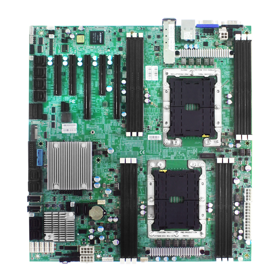
Chapter 1� Product Features 1�1 Components VIRGO Aspeed AST2500 BMC + Video (IPMI 2.0) 6 x DDR4 DIMM Slots 6 Channel (from CPU1) 3 x PCIe Gen3 x8 Slot 6 x SFF-8643 Connectors (Supports 6 x PCIe x4 for NVMe SSD) -
Page 10: 1�2 Specifications
Chapter 1. Product Features 1�2 Specifications Intel® Xeon® Scalable Processors Processor (Skylake/Cascade Lake/Cascade Lake Refresh) Support Controller with dual SFP+ rear connectors 165W CPU TDP Network (KR/SFI/XFI) by onboard header UPI Speeds 10.4 GT/s, 9.6 GT/s Controller (optional by PCH C624 SKU) Socket P0 (LGA-3647 Socket) Socket Type On-board... -
Page 11: 1�3 Feature
Instruction Set (AVX-512, VMD, QAT - optional by PCH SKU), Speed Shift Technology, UPI link speeds up to 10.4GT/s, the Virgo server board enable next generation server solutions with an incredible leap in performance in a standard EATX form factor platform. -
Page 12: Chapter 2� Hardware Setup
Chapter 2� Hardware Setup This section describes a simple instruction guide for installing the hardware components on the serverboard system. Turn off and unplug all system and peripheral devices before proceeding. 2�1 Central Processing Unit Setup The serverboard supports dual Xeon scalable processors and Socket P0 (LGA-3647). 2�1�1 Processor Installation To ensure a safe and easy setup, you need to prepare before installation: ... - Page 13 Chapter 2. Hardware Setup Processor Socker Assembly: The server board includes two processor sockets (LGA-3647), supports two Intel® Xeon® Processor Scalable Family and has a Thermal Design Power (TDP) of up to 165W on selected models. PHM (Processor Heat sink Module) Component: Non Frabic Processor Non Frabic...
- Page 14 Chapter 2. Hardware Setup PHM Screw Installation Order: The PHM sits level with the processor socket assembly. The PHM is NOT installed properly if it does not sit level with the processor socket assembly. Once the PHM is seated over the processor socket assembly, the four heat sink torque screws must be secured in the following order as shown below.
-
Page 15: 2�2 System Memory
PCIE4 PCIE3 PCIE2 PCIE1 SFF-8643 SFF-8643 NOTE -In Virgo case, the lanes from CPU#0 are routed to PCIe slots 1 & 5 and onboard SFF- 8643. -The lanes from CPU#1 are routed to PCIe slots 2/3/4 and the onboard SFF-8643. -
Page 16: Dimm Population
Chapter 2. Hardware Setup 2�2�1 DIMM Population JDIMML0 JDIMMC0 JDIMMK0 JDIMMB0 JDIMMJ0 JDIMMA0 DIMM Numbers DIMM ARRANGMENT CPU 0 CPU 0 CPU 0 CPU 1 CPU 1 CPU 1 CPU1 CPU0 2 DIMMs JDIMM_L0 JDIMM_C0 JDIMMG0 JDIMMD0 JDIMMH0 JDIMME0 JDIMMI0 JDIMMF0 JDIMML0 JDIMMC0... - Page 17 Chapter 2. Hardware Setup JDIMML0 JDIMMC0 JDIMMK0 JDIMMB0 JDIMMJ0 JDIMMA0 CPU1 CPU0 JDIMM_L0 JDIMM_C0 CPU 0 CPU 0 CPU 0 CPU 1 CPU 1 CPU 1 JDIMM_K0 JDIMM_B0 10 DIMMs JDIMM_J0 JDIMM_A0 JDIMM_G0 JDIMM_D0 JDIMMG0 JDIMMD0 JDIMM_I0 JDIMM_F0 JDIMMH0 JDIMME0 JDIMMI0 JDIMMF0 JDIMML0...
-
Page 18: Dcpmm Dimm Population
Chapter 2. Hardware Setup 2�2�2 DCPMM DIMM Population CPU0 CPU1 DIMM JDIMMF0 JDIMME0 JDIMMD0 JDIMMA0 JDIMMB0 JDIMMC0 JDIMML0 JDIMMK0 JDIMMJ0 JDIMMG0 JDIMMH0 JDIMMI0 Direct DCPMM DRAM1 DRAM1 DRAM1 DRAM1 DCPMM Mode Memory DCPMM DRAM2 DRAM2 DRAM2 DRAM2 DCPMM Mode Mixed Memory DCPMM DRAM3... -
Page 19: Memory Installation
Chapter 2. Hardware Setup 2�2�3 Memory Installation Step 1 Unlock the dimm socket by pressing the retaining clips outward. Step 2 Insert the memory module into the slot. Make sure that the DIMM notch is accurately positioned. DIMM notch Step 3 Close the retaining clips to complete installation. -
Page 20: Chapter 3� Motherboard Settings
Chapter 3� Motherboard Settings This section describes the jumpers, internal connectors and internal LEDs setting on Virgo motherboard. The motherboard layout and important jumper settings are listed below. 3�1 Block Diagram Platform Environment Control Interface(PECI) DIMM #L0 DIMM #B0 DIMM #D0... -
Page 21: 3�2 Content List
Chapter 3. Motherboard Settings 3�2 Content List Connector/Jumper/Header Location Connector/Jumper/Header Location Power Supply JPWR1, JPWR3, Front I/O USB Header JUSB_INT Connector JPWR4 Power Supply JPWR2 SSI Front Panel Header JFRNT_SSI Connector External Thermal J2, J13, J24 NGFF Connector JNGFF Sensor CPU Fan Header J1 &... -
Page 22: 3�3 Placement
Chapter 3. Motherboard Settings 3�3 Placement CPU1 CPU1 CPU0 CPU0 33 31 27 26 41 40 39 38b 3a 35b 35a 30 29 25b 25a... -
Page 23: 3�4 Connector And Jumper
Chapter 3. Motherboard Settings 3�1�4 Connector 1a ~ 1c Power Connector (JPWR1, JPWR3 & JPWR4) GND 1 5 +12V GND 2 6 +12V GND 3 7 +12V GND 4 8 +12V 2 Power Connector (JPWR2) +3.3V 1 13 +3.3V +3.3V 2 14 +12V GND 3 15 GND... - Page 24 Chapter 3. Motherboard Settings 8 PMBus Header (JPMBUS) 1 SMB_PMBUS_CLK 2 SMB_PMBUS_DATA 3 PMBUS_ALERT_N 4 GND 5 +3.3V 9 SAS IOC UART Header (J20) 1 UART0_TX 2 GND 3 UART0_RX 4 SAS3008_1V8 15 PCH SSGPIO Header (JSSGPIO) GND 1 2 PCH_SSDATAOUT0 PCH_SSDATAOUT1 3 4 PCH_SSLOAD +3.3V 5...
- Page 25 Chapter 3. Motherboard Settings 28 SSI Front Panel Header (JFRNT_SSI) +3.3V 1 2 +3.3V_DUAL KEY (no pin) 3 4 +5V_AUX PWR_LED# 5 6 UIDLED_OUT# +3.3V 7 8 SYS_HEALTH#2 HD_LED# 9 10 SYS_HEALTH#1 SW_PWR_BTN# 11 12 LAN1_LINK_UP GND 13 14 LAN1_TRAFFIC SW_RST_BTN# 15 16 I2C8SDA GND 17 18 I2C8SCL UID_SW_IN# 19 20 INTRUDER#...
- Page 26 Chapter 3. Motherboard Settings 39 VROC KEY Header (JRAID_KEY) 1 GND 2 +3.3V_DUAL 3 GND 4 PCH_GPP_C10 40 LCM Header (JLCM) 1 SW_PWR_BTN# 2 SW_RST_BTN# 3 TXDC 4 RXDC 5 GND 41 10GbE Carrier Board Header (J28) +3.3V_DUAL 1 2 +3.3V_DUAL LAN_LED3_ACT 3 4 LAN_LED2_ACT LAN_LED3_10G 5...
-
Page 27: Jumper
Chapter 3. Motherboard Settings 51 Front VGA Header (VGA_INT) DVO_5V 1 2 GND GND 3 4 DACROA DDC_DATAO 5 6 GND AVSYNCO 7 8 DACGOA AHSYNCO 9 10 GND DDC_CLKO 11 12 DACBOA Power Connector (JPWR5) GND 1 3 +12V GND 2 4 +12V 3�1�5 Jumper... - Page 28 Chapter 3. Motherboard Settings 19 Flash Descriptor Security override Jumper (J8) Setting Short Flash Security override Open Normal Default 20 NTB Jumper (JNTB) JNTB Setting Short Downstream port Open Upstream port Default 22 System Power Good Lock (JPG_LOCK) JPG_LOCK Setting Short Lock Open...
-
Page 29: 3�5 System Led Indicator
Chapter 3. Motherboard Settings 3�1�6 Internal LED LAN2 10G LED LAN1 10G LED SFP+ LAN1 1G LED LAN2 1G LED LAN4 1G/10G LED LAN3 1G/10G LED BMC Heart Beat LED SAS IOC Status LED NVME Hot-Plug LED (PHY0~PHY7) SAS IOC Heart Beat LED NGFF SAS IOC Error LED System PG LED... -
Page 30: Chapter 4� Bios Configuration Settings
Chapter 4� BIOS Configuration Settings This chapter demonstrates how to configure the UEFI BIOS settings in your system device. You can enter the BIOS screen during system startup. To enter BIOS configuration settings, • Press Esc key during the Power-On-Self-Test (POST) To enter BIOS after POST, you have to restart the system by using one of the three methods: •... -
Page 31: 4�2 Bios Setup
Chapter 4. BIOS Configuration Settings 4�2 BIOS Setup 4�2�1 Menu Press and to select the options of the menu bar. Press Enter to access the option screen. Menu Description Main Displays basic system information and date & time. Advanced Allows configuration of advanced system settings. - Page 32 Chapter 4. BIOS Configuration Settings There will be a message “Entering SETUP” displayed on the diagnostics screen. Identify the BIOS version. NOTE For the official released version, the last digit of the BIOS version must end in a “0.“...
- Page 33 Chapter 4. BIOS Configuration Settings Load Optimal Default Setting. Save the setting and exit the BIOS setup utility.
-
Page 34: Update
Chapter 4. BIOS Configuration Settings 4�2�3 Update To identify the latest BIOS version, please check the BIOS setup. Update BIOS by INSYDE H2OFFT-D utility under DOS environment If you need to update Flash in the DOS environment, please use H2OFFT-D utility. To use this utility, you must include the flash.bat , H2OFFT-D.exe and bin file in the same folder. -
Page 35: Dcpmm Setup
Chapter 4. BIOS Configuration Settings 4�2�4 DCPMM Setup Refer to section 4.2.2 step 1 and 2 to enter the Front Page menu. Enter the option "Device Management." In "Device Management" page, enter "Intel(R) Optane(TM) DC Persistent Memory Configuration"... - Page 36 Chapter 4. BIOS Configuration Settings • Regions • Namespaces • Total Capacity • Diagnostics • Preferences...
-
Page 37: 4�3 Main
Chapter 4. BIOS Configuration Settings 4�3 Main 4�3�1 Main Main System time Configures the current time. System date Configures the current date. -
Page 38: 4�4 Advanced
Chapter 4. BIOS Configuration Settings 4�4 Advanced 4.4.1 Peripheral Configuration Peripheral Configuration PCIe SR-IOV [Enable] Disable PCIe ARI Enable [Disable] ARI Forward Enable [Disable] Spread Spectrum Enable [Disable] 4.4.2 Video Configuration Video Configuration Display Mode Plug In First [On Board First] 4�4�3 OEMBoard Function OEMBoard Function SMBIOS Updated... -
Page 39: Sio Ast2500
Chapter 4. BIOS Configuration Settings 4�4�4 SIO AST2500 SIO AST2500 Serial Port A Auto [Enable] Disable Base I/O Address [3F8] Interrupt IRQ3 [IRQ4] Serial Port B Auto [Enable] Disable Base I/O Address [2F8] Interrupt [IRQ3] IRQ4 Serial Port D Auto Enable [Disable] Base I/O Address... - Page 40 Chapter 4. BIOS Configuration Settings Volatile Memory [Auto] Mode AppDirect cache Auto Enable [Disable] eADR Support Auto Enable [Disable] 1LM Memory 256B Target, 64B Target, 64B Interleave [Auto] 256B Channel Channel Granularity IMC Interleaving [Auto] 1-way Interleave 2-way Interleave Memory Map [Auto] 1-way Interleave Channel...
- Page 41 Chapter 4. BIOS Configuration Settings App Direct [Enable] Disable Memory Hole SWSMI [ASL] implementation SMBus Max Min= 0, Max= 4294967295, [350] Access Time NGNVM DIMM NGN Configuration Secure Erase SMBus Release Min= 0, Max= 4294967295, [150] Unit Delay Erase All DIMMs Enable [Disable] S0 CH0~5 S1 CH0~5...
- Page 42 Chapter 4. BIOS Configuration Settings PCI 64-Bit Resource [Enable] Disable Allocation PCIe Train by BIOS [Yes] PCIe Hot Plug Auto Manual Enable [Disable] PCIe ACPI Hot Plug Enable [Disable] Per-Port PCI-E Completion Timeout (Global) [No] Per-Port Disable 50us to 10ms 16ms to 55ms 65ms to 210ms [260ms to PCI-E Global Timeout...
- Page 43 Chapter 4. BIOS Configuration Settings Intel® VMD 32-bit non-prefetchable for Volume [64-bit non-prefetchable] Intel® VMD MemBar2 IIO Configuration Management technology attribute Device on 64-bit prefetchable Socket 0 WFR Uncore GV Auto Enable [Disable] Rate Reduction Uncore Freq [Enable] Disable Scaling (UFS) [128 Heavy] 256 Light 256 Heavy...
- Page 44 Chapter 4. BIOS Configuration Settings Non-Snoop Enable [Disable] Latency Override Latency Non-Snoop Tolerence Latency Min=0, Max=7, [0] Requirement Multiplier Non-Snoop Min=0x0, Max=0x3ff Latency Value IIO0_PKGC_ Enable CLK_GATE_ [Disable] DISABLE IIO1_PKGC_ Enable CLK_GATE_ [Disable] DISABLE IIO2_PKGC_ Enable CLK_GATE_ [Disable] DISABLE UPI01_PKGC_ Enable CLK_GATE_ [Disable]...
-
Page 45: Me Configuration
Chapter 4. BIOS Configuration Settings 4.4.6 ME Configuration ME Configuration Altitude Min=0x0, Max=0xffff, [0x8000] Server ME General ME Configuration Configuration MCTP Bus Owner Min=0x0, Max=0xffff, [0x0] ME Initialization Min=0, Max=12, [2] Complete Timeout Enable HSIO [Enable] Disable Messaging DRAM Init Done None Enable [Auto - true status]... -
Page 46: Pch Configuration
Chapter 4. BIOS Configuration Settings 4.4.7 PCH Configuration PCH Configuration PCH Devices PCH state after G3 [S5] Last State SATA Controller [Enable] Disable Configure SATA as [AHCI] RAID Support Aggressive Link Power [Enable] Disable Management Port 0~7 [Enable] Disable SATA Port 0 DevSlp Enable [Disable] PCH SATA... -
Page 47: H2O Ipmi Configuration
Chapter 4. BIOS Configuration Settings 4.4.8 H2O IPMI Configuration H2O IPMI Configuration IPMI Support [Enable] Disable BMC Warmup Time Min=0, Max=240, [90] ACPI SPMI Table [Enable] Disable Boot Option Support [Enable] Disable Set BIOS version to [Enable] Disable Watchdog Timer Support Enable [Disable] Not disable in OS... -
Page 48: H2O Event Log Config Manager
Chapter 4. BIOS Configuration Settings 4.4.11 H2O Event Log Config Manager H2O Event Log Config Manager BIOS Log Event To BIOS Event Log BIOS Event [BMC SEL] Memory Disable Configuration Log Viewer Event Log [Stop Overwrite Clear All Full option Logging] POST Message Enable... -
Page 49: 4�5 Security
Chapter 4. BIOS Configuration Settings 4�5 Security 4�5�1 Security Security Current TPM Device Not Detected TPM 1.2 [TPM 2.0] TPM Active PCR Hash [SHA1, SHA256] Algorithm TPM Hardware Supported Hash [SHA1, SHA256] Algorithm TrEE Protocol Version 1.0 [1.1] TPM Availability [Available] Hidden TPM Operation... -
Page 50: 4�6 Power
Chapter 4. BIOS Configuration Settings 4�6 Power 4�6�1 Power Power Wake on PME Enable [Disable]... -
Page 51: 4�7 Boot
Chapter 4. BIOS Configuration Settings 4�7 Boot 4�7�1 Boot Boot Boot Type [Dual Boot Type] Legacy Boot Type UEFI Boot Type Quick Boot [Enable] Disable Quiet Boot Enable [Disable] Network Stack [Enable] Disable [Disable] UEFI:IPv4 UEFI:IPv6 PXE Boot capability UEFI:IPv4/UEFI:IPv6 [Legacy] Add Boot Options First... -
Page 52: 4�8 Exit
Chapter 4. BIOS Configuration Settings 4�8 Exit 4�8�1 Exit Exit Exit Saving Changes Exit system setup and save your changes. Save Change Without Exit Save your changes without exiting the system. Exit Discarding Changes Discard your changes when existing the system. Load Optimal Defaults Load optimal default items. -
Page 53: Chapter 5� Technical Support
Boulvard Suite 404 Fremont, CA 94539, United States Tel: +1-510-573-6730 Sales Email: sales@aicipc�com Support Email: support@aicipc�com For additional technical support or questions about trouble shooting, please contact the AIC® representative nearest to you or visit our AIC® website for more information. AIC® website: https://www.aicipc.com/en/faq.
Need help?
Do you have a question about the Virgo and is the answer not in the manual?
Questions and answers