Table of Contents
Advertisement
Quick Links
Advertisement
Table of Contents

Related Manuals for AIC Vela


Summary of Contents for AIC Vela
- Page 1 Vela Server Motherboard User's Manual UM_Vela_v1.3_030521...
-
Page 2: Table Of Contents
Table of Contents Preface �������������������������������������������������������������������������������������������������������� i Safety Instructions �������������������������������������������������������������������������������������� ii About This Manual ������������������������������������������������������������������������������������� iii Chapter 1� Product Features ���������������������������������������������������������������������� 1 1�1 Component ��������������������������������������������������������������������������������������� 1 1�2 Specifications ����������������������������������������������������������������������������������� 2 1�3 Feature ��������������������������������������������������������������������������������������������� 3 Chapter 2� Hardware Setup ������������������������������������������������������������������������ 4 2�1 Central Processing Unit Setup ���������������������������������������������������������� 4 2.1.1 Processor Installation .................. - Page 3 4.6.1 Power ........................42 4�7 Boot ������������������������������������������������������������������������������������������������ 43 4.7.1 Boot ........................43 4�8 Exit ������������������������������������������������������������������������������������������������� 44 4.8.1 Exit........................44 Chapter 5� BMC Configuration Settings ��������������������������������������������������� 45 5�1 Login ���������������������������������������������������������������������������������������������� 45 5�2 Web GUI ���������������������������������������������������������������������������������������� 46 5.2.1 Menu Bar ......................46 5.2.2 User Information and Quick Button ..............47 5.2.3 Dashboard ......................
- Page 4 Document Release History Release Date Version Update Content September User's Manual release to public. 2019 November Specification update. 2019 January Manual cover update. 2021 March Connector update. 2021...
- Page 5 Copyright © 2019 AIC®, Inc� All Rights Reserved� This document contains proprietary information about AIC® products and is not to be disclosed or used except in accordance with applicable agreements.
-
Page 6: Preface
Disclaimer AIC® shall not be liable for technical or editorial errors or omissions contained herein. The information provided is provided "as is" without warranty of any kind. To the extent permitted by law, neither AIC®... -
Page 7: Safety Instructions
Safety Instructions When installing, operating, or performing maintenance on this equipment, the following safety precautions should always be taken into account in order to reduce the risk of fire, electric shock, and personal injury. Carefully read the safety instructions below before using this product. •... -
Page 8: About This Manual
This document pellucidly presents a brief overview of the product design, device installation, and firmware settings for the Vela motherboard. For the latest version of this user's manual, please refer to the AIC website: https://www.aicipc.com/en/productdetail/51202. -
Page 9: Chapter 1� Product Features
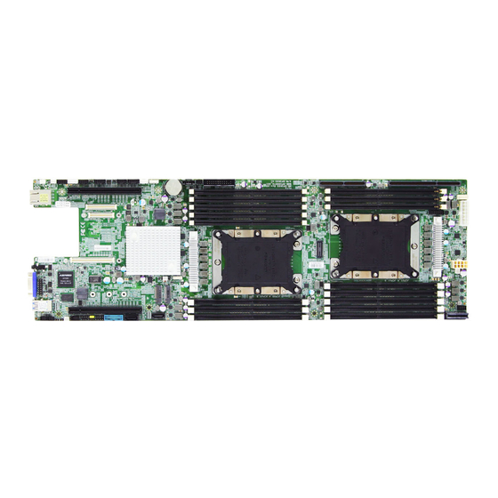
Chapter 1� Product Features This section describes the hardware specifications and features of the Vela motherboard. The fundamental components of the Vela severboard are provided below. 1�1 Component Vela Serverboard PCIe Gen3 x16 8 x SATA3 Intel PCH (from CPU0) -
Page 10: 1�2 Specifications
Chapter 1. Product Features 1�2 Specifications Intel® Xeon® Scalable Processors Intel ® Lewisburg PCH on-chip solution Processor (Skylake/Cascade Lake/Cascade Lake Refresh) • 2 x SATA 6.0 Gb/s (by 2 x SATA 7 pin) Support SATA • 8 x SATA 6.0 Gb/s by edge slot for extension 240W CPU TDP Aspeed AST2500 Advanced PCIe Graphics &... -
Page 11: 1�3 Feature
Featured with ground breaking technologies including Intel® Next Generation Microarchitecture and Instruction Set (AVX-512, VMD, QAT - optional by PCH SKU), Speed Shift Technology, UPI link speeds up to 10.4GT/s, the Vela server board enable next gener- ation server solutions with an incredible leap in performance. -
Page 12: Chapter 2� Hardware Setup
Chapter 2� Hardware Setup This chapter provides the graphic detail and basic instruction for hardware installation. Turn off the system and unplug all peripheral devices before proceeding. 2�1 Central Processing Unit Setup The serverboard supports dual Xeon scalable processors and Socket P0 (LGA-3647). 2�1�1 Processor Installation To ensure a safe and easy setup, you need to prepare before installation: ... - Page 13 Chapter 2. Hardware Setup Processor Socket Assembly: The server board includes two processor sockets (LGA-3647), supports one or two of the Intel® Xeon® Processor Scalable Family and has a Thermal Design Power (TDP) of up to 165W on selected models. PHM (Processor Heatsink Module) Component: Non Frabic Processor...
- Page 14 Chapter 2. Hardware Setup The PHM sits level with the processor socket assembly. The PHM is NOT installed properly if it does not sit level with the processor socket assembly. Once the PHM is seated over the processor socket assembly, the four heat sink torque screws must be tightened in order as shown below.
-
Page 15: 2�2 System Memory
Chapter 2. Hardware Setup 2�2 System Memory 2�2�1 Placement The DIMMs are displayed on the Vela board as JDIMMC0/ JDIMMB0/JDIMMA0/JDIMMD0/ JDIMME1/ JDIMME0/JDIMMF1/ JDIMMF0/JDIMML0/JDIMMK0/ JDIMMK1/JDIMMJ0/JDIMMJ1/ JDIMMG0/JDIMMH0/JDIMMI0. To ensure satisfactory performance, you need to: Verify the DIMM type: This product supports DDR4 RDIMM/LRDIMM with EEC (Error Correction Code). -
Page 16: Dimm Population
Chapter 2. Hardware Setup 2�2�2 DIMM Population JDIMMF0 JDIMMI0 JDIMMF1 JDIMMH0 JDIMME0 JDIMMG0 JDIMME1 JDIMMD0 DIMM Number DIMM Arrangement CPU1 CPU0 CPU1 2 DIMMs CPU0 JDIMMC0 JDIMMI0 JDIMMJ1 JDIMMJ0 JDIMMA0 JDIMMK1 JDIMMB0 JDIMMK0 JDIMMC0 JDIMML0 JDIMMF0 JDIMMI0 JDIMMF1 JDIMMH0 JDIMME0 JDIMMG0 JDIMME1 JDIMMD0... - Page 17 Chapter 2. Hardware Setup JDIMMF0 JDIMMI0 JDIMMF1 JDIMMH0 JDIMME0 JDIMMG0 JDIMME1 DIMM Number DIMM Arrangement JDIMMD0 CPU0 CPU1 JDIMMC0 JDIMMI0 CPU1 JDIMMB0 JDIMMH0 10 DIMMs CPU0 JDIMMA0 JDIMMG0 JDIMMF0 JDIMML0 JDIMME0 JDIMMK0 JDIMMJ1 JDIMMJ0 JDIMMA0 JDIMMK1 JDIMMB0 JDIMMK0 JDIMML0 JDIMMC0 JDIMMF0 JDIMMI0 JDIMMF1...
-
Page 18: Dcpmm Dimm Population
Chapter 2. Hardware Setup 2�2�3 DCPMM DIMM Population CPU0 DIMM JDIMMF0 JDIMMF1 JDIMME0 JDIMME1 JDIMMD0 JDIMMA0 JDIMMB0 JDIMMC0 App Direct DCPMM DRAM1 DCPMM DRAM1 DRAM1 DCPMM DRAM1 DRAM1 Mode Memory DCPMM DRAM2 DCPMM DRAM2 DRAM2 DCPMM DRAM2 DRAM2 Mode Mixed Memory DCPMM DRAM3... -
Page 19: Installation
Chapter 2. Hardware Setup 2�2�4 Installation Step 1 Unlock the DIMM socket by pressing the retaining clips outward. Step 2 Insert the memory module into the slot. Make sure that the DIMM notch is accurately positioned. DIMM notch Step 3 Close the retaining clips to complete installation. -
Page 20: Chapter 3� Motherboard Settings
Chapter 3� Motherboard Settings This section provides illustrations that display the internal jumpers, connectors, and system LED indicators on the Vela motherboard. The motherboard layout and essential connectors are listed below for your reference. 3�1 Block Diagram... -
Page 21: 3�2 Content List
Chapter 3. Motherboard Settings 3�2 Content List Connector and Header Placement Connector and Header Placement 1 VGA Connector JVGA_INT 17 Rack Connector JRACK OCP Mezzaine Power Supply Connector CN1~3 JPWR1 Connector (2 x 4 pin) PCIE1 3b PCIe Connector 19 LAN Header JLAN2 PCIE2 JCOM1... -
Page 22: 3�3 Placement
Chapter 3. Motherboard Settings 3�3 Placement CPU0 CPU0 CPU1 CPU1... -
Page 23: 3�4 Connector And Jumper
Chapter 3. Motherboard Settings 3�4 Connector and Jumper 3�4�1 Connector 1 VGA Connector (JVGA_INT) GND 1 2 DACROA VGA abbreviates for Video Graphics Array. DACGOA 3 4 N.C. This is a standard 15-pin D-sub connector DDC_DATAO 5 6 GND used for video output. GND 7 8 DACBOA N.C. - Page 24 Chapter 3. Motherboard Settings 7a BMC I C Header (JBMC_I2C1) C abbreviates for Inter-Integrated Circuit. 1 I2C10SCL This 3-pin header is an I C bus that provides a 2 I2C10SDA interconnection between the BMC and chassis 3 GND devices. 7b IPMB Header (JBMC_I2C2) 1 I2C1SDA IPMB abbreviates for Intelligent Platform Management Bus.
- Page 25 Chapter 3. Motherboard Settings 15 Power Supply Connector (J13) This 5-pin connector provides the motherboard 1 +5V_AUX with power. 2 +5V_AUX 3 ATX_GD 4 PS_ON# 5 GND 16 Power Supply Connector (JPWR2) This 14-pin connector provides the GND 1 8 +12V motherboard with power.
- Page 26 Chapter 3. Motherboard Settings 26 Front I/O Header (JUSB_INT1) This is a 11-pin front I/O header. +5V_USB23 1 20 KEY (no pin) PCH_FP_USB3_RX_N2 2 19 +5V_USB23 10 11 PCH_FP_USB3_RX_P2 3 18 PCH_FP_USB3_RX_N3 GND 4 17 PCH_FP_USB3_RX_P3 PCH_FP_USB3_TX_N2 5 16 GND PCH_FP_USB3_TX_P2 6 15 PCH_FP_USB3_TX_N3 GND 7...
-
Page 27: Jumper
Chapter 3. Motherboard Settings 3�4�2 Jumper A NCSI_RXER (J5) Setting Short Enable Open Disable Default B BMC Debug port Configurations (J9) Setting Short Disable Open BMC Debug port Default C Top Swap Override Jumper (J8) Setting Enable Top swap Short mode Disable Top Open... - Page 28 Chapter 3. Motherboard Settings H Power Good Lock Jumper (JPG_LOCK) JPG_LOCK Setting Short Enable Open Disable Default I Flash Descriptor Security verride Jumper (J4) Setting Flash security Short override Open Disable Default J BMC Reset Jumper (JBMC_RST) JBMC_RST Setting Short Reset BMC Open Normal...
-
Page 29: Led Indicator
Chapter 3. Motherboard Settings 3�4�3 LED Indicator Green (Blinking) BMC activity is detected. BMC Heart Beat BMC is not active. Green System power good is ready. SYS PG LED S y s t e m p o w e r g o o d i s n o t ready. -
Page 30: Chapter 4� Bios Configuration Settings
Chapter 4� BIOS Configuration Settings This chapter demonstrates how to configure the UEFI BIOS settings in your system device. You can enter the BIOS screen during system startup. To enter BIOS configuration settings, • Press Esc key during the Power-On-Self-Test (POST) To enter BIOS after POST, you have to restart the system by using one of the three methods: •... -
Page 31: 4�2 Bios Setup
Chapter 4. BIOS Configuration Settings 4�2 BIOS Setup 4�2�1 Menu Press and to select the options of the menu bar. Press Enter to access the option screen. Menu Description Main Displays basic system information and date & time. Advanced Allows configuration of advanced system settings. - Page 32 Chapter 4. BIOS Configuration Settings There will be a message “Entering SETUP” displayed on the diagnostics screen. Identify the BIOS version. NOTE For the official released version, the last digit of the BIOS version must end in a “0.“ ...
-
Page 33: Update
Chapter 4. BIOS Configuration Settings 4�2�3 Update To identify the latest BIOS version, please check the BIOS setup. Update BIOS by INSYDE H2OFFT-D utility under DOS environment If you need to update Flash in the DOS environment, please use H2OFFT-D utility. To use this utility, you must include the flash.bat , H2OFFT-D.exe, and bin file in the same folder. -
Page 34: Dcpmm Setup
Chapter 4. BIOS Configuration Settings 4�2�4 DCPMM Setup Refer to section 4.2.2 step 1 and 2 to enter the Front Page menu. Enter the option "Device Management." In "Device Management" page, enter "Intel(R) Optane(TM) DC Persistent Memory Configuration"... - Page 35 Chapter 4. BIOS Configuration Settings Intel(R) Optane(TM) DC Persistent Memory Configuration • DIMMs • Regions • Namespaces...
- Page 36 Chapter 4. BIOS Configuration Settings • Total Capacity • Diagnostics • Preferences...
-
Page 37: 4�3 Main
Chapter 4. BIOS Configuration Settings 4�3 Main Main Option Key: 4�3�1 Main Main System time Configures the current time. System date Configures the current date. -
Page 38: 4�4 Advanced
Chapter 4. BIOS Configuration Settings 4�4 Advanced Advanced Option Key: 4.4.1 Peripheral Configuration Peripheral Configuration PCIe SR-IOV [Enable] Disable PCIe ARI Enable [Disable] ARI Forward Enable [Disable] Spread Spectrum Enable [Disable] 4.4.2 Video Configuration Video Configuration Display Mode Plug In First [On Board First] 4�4�3 OEMBoard Function OEMBOARD Function... -
Page 39: Sio Ast2500
Chapter 4. BIOS Configuration Settings 4�4�4 SIO AST2500 SIO AST2500 Serial Port A Auto [Enable] Disable Base I/O Address [3F8] Interrupt IRQ3 [IRQ4] Serial Port B Auto [Enable] Disable Base I/O Address [2F8] Interrupt [IRQ3] IRQ4 Serial Port D Auto Enable [Disable] Base I/O Address... - Page 40 Chapter 4. BIOS Configuration Settings Volatile Memory [Auto] Mode AppDirect cache Auto Enable [Disable] eADR Support Auto Enable [Disable] 1LM Memory 256B Target, 64B Target, 64B Interleave [Auto] 256B Channel Channel Granularity Memory Map IMC Interleaving [Auto] 1-way Interleave 2-way Interleave [Auto] 1-way Interleave Channel...
- Page 41 Chapter 4. BIOS Configuration Settings App Direct [Enable] Disable Memory Hole SWSMI [ASL] implementation SMBus Max Min= 0, Max= 4294967295, [350] Access Time NGNVM DIMM NGN Configuration Secure Erase SMBus Release Min= 0, Max= 4294967295, [150] Unit Delay Erase All DIMMs Enable [Disable] S0 CH0~5 S1 CH0~5...
- Page 42 Chapter 4. BIOS Configuration Settings PCI 64-Bit Resource [Enable] Disable Allocation PCIe Train by BIOS [Yes] PCIe Hot Plug Auto Manual Enable [Disable] PCIe ACPI Hot Plug Enable [Disable] Per-Port PCI-E Completion Timeout (Global) [No] Per-Port Disable 50us to 10ms 16ms to 55ms 65ms to 210ms [260ms to PCI-E Global Timeout...
- Page 43 Chapter 4. BIOS Configuration Settings Intel® VMD 32-bit non-prefetchable for Volume [64-bit non-prefetchable] Intel® VMD MemBar2 IIO Configuration Management technology attribute Device on 64-bit prefetchable Socket 0 WFR Uncore GV Auto Enable [Disable] Rate Reduction Uncore Freq [Enable] Disable Scaling (UFS) [128 Heavy] 256 Light 256 Heavy...
- Page 44 Chapter 4. BIOS Configuration Settings Force Non- Snoop Latency Min=0x0, Max=0x3ff, [0x0] Override Non-Snoop Enable [Disable] Latency Latency Override Tolerence Non-Snoop Requirement Latency Min=0, Max=7, [0] Multiplier Non-Snoop Min=0x0, Max=0x3ff, [0x0] Latency Value IIO0_PKGC_ Enable CLK_GATE_ [Disable] DISABLE IIO1_PKGC_ Enable CLK_GATE_ [Disable] DISABLE...
-
Page 45: Me Configuration
Chapter 4. BIOS Configuration Settings 4.4.6 ME Configuration ME Configuration Altitude Min=0x0, Max=0xffff, [0x8000] Server ME General ME Configuration Configuration MCTP Bus Owner Min=0x0, Max=0xffff, [0x0] ME Initialization Min=0, Max=12, [2] Complete Timeout Enable HSIO [Enable] Disable Messaging DRAM Init Done None Enable [Auto - true status]... -
Page 46: Pch Configuration
Chapter 4. BIOS Configuration Settings 4.4.7 PCH Configuration PCH Configuration PCH Devices PCH state after G3 [S5] Last State SATA Controller [Enable] Disable Configure SATA as [AHCI] RAID Support Aggressive Link Power [Enable] Disable Management Port 0~7 [Enable] Disable SATA Port 0 DevSlp Enable [Disable] PCH SATA... -
Page 47: H2O Ipmi Configuration
Chapter 4. BIOS Configuration Settings 4.4.8 H2O IPMI Configuration H2O IPMI Configuration IPMI Support [Enable] Disable BMC Warmup Time Min=0, Max=240, [90] ACPI SPMI Table [Enable] Disable Boot Option Support [Enable] Disable Set BIOS version to [Enable] Disable Watchdog Timer Support Enable [Disable] Not disable in OS... -
Page 48: H2O Event Log Config Manager
Chapter 4. BIOS Configuration Settings 4.4.11 H2O Event Log Config Manager H2O Event Log Config Manager BIOS Log Event To BIOS Event Log BIOS Event [BMC SEL] Memory Disable Configuration Log Viewer Event Log [Stop Overwrite Clear All Full option Logging] POST Message Enable... -
Page 49: 4�5 Security
Chapter 4. BIOS Configuration Settings 4�5 Security Security Option Key: 4�5�1 Security Security Current TPM Device Not Detected TPM 1.2 [TPM 2.0] TPM Active PCR Hash [SHA1, SHA256] Algorithm TPM Hardware Supported Hash [SHA1, SHA256] Algorithm TrEE Protocol Version 1.0 [1.1] TPM Availability [Available]... -
Page 50: 4�6 Power
Chapter 4. BIOS Configuration Settings 4�6 Power Power Option Key: 4�6�1 Power Power Wake on PME Enable [Disable]... -
Page 51: 4�7 Boot
Chapter 4. BIOS Configuration Settings 4�7 Boot Boot Option Key: 4�7�1 Boot Boot Boot Type [Dual Boot Type] Legacy Boot Type UEFI Boot Type Quick Boot [Enable] Disable Quiet Boot Enable [Disable] Network Stack [Enable] Disable [Disable] UEFI:IPv4 UEFI:IPv6 PXE Boot capability UEFI:IPv4/UEFI:IPv6 [Legacy] Add Boot Options... -
Page 52: 4�8 Exit
Chapter 4. BIOS Configuration Settings 4�8 Exit Exit Option Key: 4�8�1 Exit Save and Exit Exit Saving Changes Exit system setup and save your changes. Save Change Without Exit Save your changes without exiting the system. Exit Discarding Changes Discard your changes when existing the system. Load Optimal Defaults Load optimal default items. -
Page 53: Chapter 5� Bmc Configuration Settings
Chapter 5� BMC Configuration Settings 5�1 Login NOTE This feature works with the JAVA 6 run time installed console environment. The BMC default IP source is DHCP. The IP address can be configured in H2O IPMI configuration as demonstrated by the example below. Step 1 Open the browser and then type in the BMC IP address. -
Page 54: 5�2 Web Gui
Chapter 5. BMC Configuration Settings 5�2 Web GUI 5�2�1 Menu Bar Click to select the options of the menu bar. Menu Description The Dashboard page gives the overall information about the status of a Dashboard device. Sensor The Sensor Readings page displays all the sensor related information. The FRU Information page displays the details for FRU devices in the FRU Information system. -
Page 55: User Information And Quick Button
Chapter 5. BMC Configuration Settings 5�2�2 User Information and Quick Button The user information and quick access buttons are located at the top right corner. It displays the logged-in user, his/her privilege and the four quick buttons allowing you to perform different functions. Button Description User... - Page 56 Chapter 5. BMC Configuration Settings 5�2�3 Dashboard The Dashboord page displays device, system, and network information. Click Dashboard on the menu bar to view the overall information of the server. 5�2�4 Sensor The Sensor page displays the status and records on related sensors. Click a record to view detailed information on a particular sensor.
-
Page 57: Fru Information
Chapter 5. BMC Configuration Settings 5�2�5 FRU Information The FRU Information page displays Basic Information, Chassis Information, Board Information and Product Information of the FRU device. Click FRU Information on the menu bar to view the details of the selected device. 5�2�6 Logs and Reports The System Inventory page displays IPMI Event Log and Video Log. -
Page 58: Settings
Chapter 5. BMC Configuration Settings 5�2�7 Settings The Settings page displays the configuration settings for KVM Mouse Setting, Media Redirection Settings, Network Settings, Platform Event Filter, Services, SMTP Settings, SSL Settings, System Firewall, User Management, and Video Recording. Settings Menu and Option Keys: Settings Mouse Mode Configuration •... -
Page 59: Remote Control
Chapter 5. BMC Configuration Settings 5�2�8 Remote Control The Remote Control page displays the configuration for power control and remote KVM. Launch KVM... - Page 60 Chapter 5. BMC Configuration Settings Procedure To Start KVM Step 1 Click Start KVM to start the H5Viewer video redirection. Step 2 Click Browse to select CD Image. Step 3 Click Start Media to redirect the selected CD image file to the Host. Step 4 To stop the recording, click Stop Record.
- Page 61 Chapter 5. BMC Configuration Settings Remote KVM Menu and Option Key Button Description Start KVM Starts the H5Viewer video redirection. Stop KVM Stops the H5Viewer video redirection. Pause Video This option is used for pausing Console Redirection. This option is used to resume the Console Redirection when the session Resume Video is paused.
- Page 62 Chapter 5. BMC Configuration Settings This menu item can be used to act as the Right <Ctrl> right-side <CTRL> key when in Console Redirection. This menu item can be used to act as Right <Alt> the right-side <ALT> key when in Console Redirection.
-
Page 63: Power Control
Chapter 5. BMC Configuration Settings 5�2�9 Power Control The Power Control page allows you to view and control the power of your server. To open Power Control, click Power Control from the menu bar. The various options of Power Control are given below. Power Off: To immediately power off the server. -
Page 64: Maintenance
Chapter 5. BMC Configuration Settings 5�2�10 Maintenance This Maintenance page displays the configuration settings for Backup Configuration, Firmware Image Location, Firmware Information, Fimware Update, Preserve Configuration, Restore Configuration, Restore Configuration, and Restore Factory Defaults. Maintenance Procedure 1. Click Check All to backup the selected configuration items. The Backup Configuration page will appear Click Download Config to save the backup file to the client system Backup Configuration... -
Page 65: Sign Out
Chapter 5. BMC Configuration Settings 5�2�11 Sign out To log out of the BMC: Method 1: Click Sign out from the menu bar. The Logout dialog box will pop out. Method 2: Click the root quick button on the top right corner of the screen. -
Page 66: 5�3 Firmware Update
1. Boot to the DOS (MS-DOS or Free DOS is workable). 2. Enter BMC firmware directory [XXXXXVEOOOYYY_ARK]; XXXXX: project name ; OOO: for Vela standard version YYY:firmware version; K: For auxiliary version 3. Execute a.bat batch file to update the BMC firmware. -
Page 67: Chapter 6� Technical Support
Chapter 6� Technical Support Taiwain, Global Headquarters South California, United States Address: No� 152, Section 4, Address: 21808 Garcia Lane Linghang N� Rd, Dayuan District, City of Industry, CA 91789, Taoyuan City 337, Taiwan United States Tel: +886-3-433-9188 Toll free: + 1-866-800-0056 Fax: +886-3-287-1818- Tel: +1-909-895-8989 Sales Email: sales@aicipc�com�tw...
Need help?
Do you have a question about the Vela and is the answer not in the manual?
Questions and answers