Table of Contents
Advertisement
Quick Links
Advertisement
Table of Contents

Subscribe to Our Youtube Channel
Related Manuals for AIC Lynx


Summary of Contents for AIC Lynx
- Page 1 Lynx Server Motherboard User's Manual UM_Lynx_v3.1_041119...
-
Page 2: Table Of Contents
Table of Contents Preface ������������������������������������������������������������������������������������������������ ii Safety Instructions ����������������������������������������������������������������������������� iii About This Manual ������������������������������������������������������������������������������ iv Chapter 1� Product Features �������������������������������������������������������������� 1 1�1 Componenets �����������������������������������������������������������������������������������1 1.2 Specifications �����������������������������������������������������������������������������������2 1�3 Feature ���������������������������������������������������������������������������������������������3 Chapter 2� Hardware Setup ���������������������������������������������������������������� 4 2�1 Central Processiong Unit Setup ���������������������������������������������������������4 2.1.1 Processor Support ....................4 2.1.2 Processor Heat Sink Module and Processor Socket Assembly .......5 2.1.3 Processor Heat Sink Module ................6... - Page 3 4.4.5 System Event Log .................... 36 4.4.6 Debug Configuration..................39 4.4.7 OEMBOARD Function ..................39 4.4.8 SIO AST2500 ....................39 4.4.9 Socket Configuration ..................40 4.4.10 ME Configuration ................... 51 4.4.11 PCH Configuration ..................53 4.4.12 H2O IPMI Configuration ................58 4.4.13 APEI Configuration ..................
- Page 4 Copyright © 2018 AIC, Inc� All Rights Reserved� This document contains proprietary information about AIC products and is not to be disclosed or used except in accordance with applicable agreements.
- Page 5 Document Release History Release Date Version Update Content November User's Manual release to public 2017 March 1. Gramnar Errors 2018 2. Add About this Manual 1. Datasheet January 2. Hardware Settings update 2019 3. SW update April BIOS update. 2019...
-
Page 6: Preface
Disclaimer AIC shall not be liable for technical or editorial errors or omissions contained herein. The information provided is provided "as is" without warranty of any kind. To the extent permitted by law, neither AIC or its affiliates, subcontractors or suppliers will be liable for incidental, special or consequential damages including downtime cost;... -
Page 7: Safety Instructions
Safety Instructions When installing, operating, or performing maintenance on this equipment, the following safety precautions should always be observed in order to reduce the risk of fire, electric shock, and personal injury. Read and understand all instructions. Observe warnings and instructions marked on the product. •... -
Page 8: About This Manual
This document pellucidly presents a brief overview of the product design, device installation, and firmware settings for the Lynx motherboard. For the latest version of this user's manual, please refer to the AIC website: http://www.aicipc.com/en/productdetail/20870. -
Page 9: Chapter 1� Product Features
(Share with Max I/O® #2) 2 x NGFF(M.2) M-Key (2280, 2242 by additional bracket) support SATA/ PCIe x2 AIC Max I/O® #2; (CPU1) AIC Max I/O® #1; (CPU0) PCIe Gen3 Supports 48 Lanes PCIe Gen3 Supports 48 Lanes (Share with OCP Mezzanine) (Share with OCP Mezzanine) 10 x SATA 3.0... -
Page 10: 1.2 Specifications
Remote Management Processor - up to 3072GB LRDIMM 3DS 8Rx4//QRx4 Graphics (Apache Pass) support 2 x AIC Max I/O® support: 10 x SATA 6.0 Gb/s ports Serial ATA PCIe Gen3 total 96 lanes; (each 48 lanes from CPU0 & CPU1) x16 (share with Max I/O®) -
Page 11: 1�3 Feature
By implementing Intel® Xeon® Scalable Processors, fully integrated microarchitecture with AIC MAX I/O® 2.0 which support up to 96 lanes of PCIe Gen3, Lynx server board can maximize your I/O intensive application demand, providing six channels per CPU with total twenty-four DIMM slots deployment which can support up to DDR4 2400/2666MHz (feature supports up to DDR4 2933MHz by next gen. -
Page 12: Chapter 2� Hardware Setup
Chapter 2� Hardware Setup Lynx User Manual Chapter 2. Hardware Setup Spica User Manual 2�1 Central Processiong Unit Setup 2�1�1 Processor Support The server board includes two processor sockets (LGA-3647) that provides support for Intel® Xeon® Processor Scalable Family processor and a Thermal Design Power (TDP) of up... -
Page 13: Processor Heat Sink Module And Processor Socket Assembly
Lynx User Manual Chapter 2. Hardware Setup 2�1�2 Processor Heat Sink Module and Processor Socket Assembly Each processor socket on the server board is pre-assembled with a loading mechanism that is designed to secure the Processor Heat Sink Module (PHM) to the server board as shown below. -
Page 14: Processor Heat Sink Module
Lynx User Manual Chapter 2. Hardware Setup 2�1�3 Processor Heat Sink Module The PHM refers to the sub-assembly where the heat sink and processor are clipped together onto the server board prior to installation. The PHM consists of the components shown below. - Page 15 Lynx User Manual Chapter 2. Hardware Setup The PHM sits level with the processor socket assembly. The PHM is NOT installed properly if it does not sit level with the processor socket assembly. Once the PHM is seated over the processor socket assembly, the four heat sink torque screws must be tightened in order as shown below.
- Page 16 Lynx User Manual Chapter 2. Hardware Setup 2�2 HFI Carrier Card for Host Fabric Interface (HFI) Supported The Intel® Fabric Passive (IFP) Internal Cable Assembly enables high speed, low loss data connections between the Intel® Xeon™ Phi™ processor (KNL-F) and chassis connections to an external network interface via QSFP +28 style connectors.
-
Page 17: 2�2 System Memory Setup
Lynx User Manual Chapter 2. Hardware Setup 2�2 System Memory Setup This server board supports 24 DDR4 2400/2666 Registered ECC SDRAM(RDIMM) / Load- Reduced DIMM (LRDIMM). 2�2�1 DIMM Installation Step 1 Unlock the dimm socket by pressing the retaining clips outward. -
Page 18: Dimm Location
Lynx User Manual Chapter 2. Hardware Setup 2�2�2 DIMM Location CPU1 JDIMMJ1 JDIMMJ0 JDIMMK1 JDIMMK0 JDIMML1 JDIMML0 JDIMMC0 JDIMMC1 JDIMMB0 JDIMMB1 JDIMMA0 JDIMMA1 CPU0 JDIMMD1 JDIMMD0 JDIMME1 JDIMME0 JDIMMF1 JDIMMF0... -
Page 19: Dimm Slot Installation Order
Lynx User Manual Chapter 2. Hardware Setup 2�2�3 DIMM Slot Installation Order DIMM DIMM Numbers Placement Numbers CPU1 CPU0 JDIMMI1 JDIMMC1 JDIMMH0 JDIMMB0 JDIMMH1 JDIMMB1 JDIMMG0 JDIMMA0 JDIMMG1 JDIMMA1 2 DIMMs JDIMM_I0 JDIMM_C0 CPU1 CPU1 CPU0 CPU0 JDIMMJ1 JDIMMD1 JDIMMJ0... - Page 20 Lynx User Manual Chapter 2. Hardware Setup CPU1 CPU0 JDIMMI1 JDIMMC1 JDIMM_I0 JDIMM_C0 JDIMMH1 JDIMMB1 JDIMMG1 JDIMMA1 JDIMM_H0 JDIMM_B0 10 DIMMs CPU1 CPU1 CPU0 CPU0 JDIMM_G0 JDIMM_A0 JDIMM_K0 JDIMM_E0 JDIMMJ1 JDIMMD1 JDIMMJ0 JDIMMD0 JDIMME1 JDIMMK1 JDIMM_L0 JDIMM_F0 JDIMMF1 JDIMML1 CPU1...
- Page 21 Lynx User Manual Chapter 2. Hardware Setup CPU1 CPU0 JDIMM_I0 JDIMM_C0 JDIMM_I1 JDIMM_C1 JDIMM_H0 JDIMM_B0 JDIMM_H1 JDIMM_B1 20 DIMMs JDIMM_G0 JDIMM_A0 CPU1 CPU1 CPU0 CPU0 JDIMM_G1 JDIMM_A1 JDIMM_J0 JDIMM_D0 JDIMMD1 JDIMMJ1 JDIMM_K0 JDIMM_E0 JDIMMK1 JDIMME1 JDIMM_L1 JDIMM_F1 JDIMM_L0 JDIMM_F0 CPU1...
-
Page 22: Chapter 3� Hardware Settings
Chapter 3� Hardware Settings Lynx User Manual Chapter 2. Hardware Setup This section provides illustrations that display the internal jumpers, connectors, and system LED indicators. 3�1 Motherboard Block Diagram Platform Environment Control Interface(PECI) USB2#9 DIMM #I1 DIMM #C1 USB2#8 USB2.0(X2) -
Page 23: 3�2 Motherboard Content List
Lynx User Manual Chapter 2. Hardware Setup Connector/Header/Jumper Location Connector/Header/Jumper Location 3�2 Motherboard Content List Power Supply COM CPU0 Configurations J15, J16 JPG_LOCK Bus Disable Jumper Jumper Power Supply PSKILL J14, J17 COM Port JCOM1, JCOM4 Disable Jumper Backplane Power... - Page 24 Lynx User Manual Chapter 2. Hardware Setup Connector/Header/Jumper Location Connector/Header/Jumper Location No Reboot (Watch 51 VROC Key Header JRAID_KEY dog) Jumper BIOS Recovery Mode ME Force Recovery Jumper Mode Jumper JNGFF1, JNGFF Connector 53 Speaker JSPKR JNGFF2 AUX Power Header...
-
Page 25: 3�3 Motherboard Layout
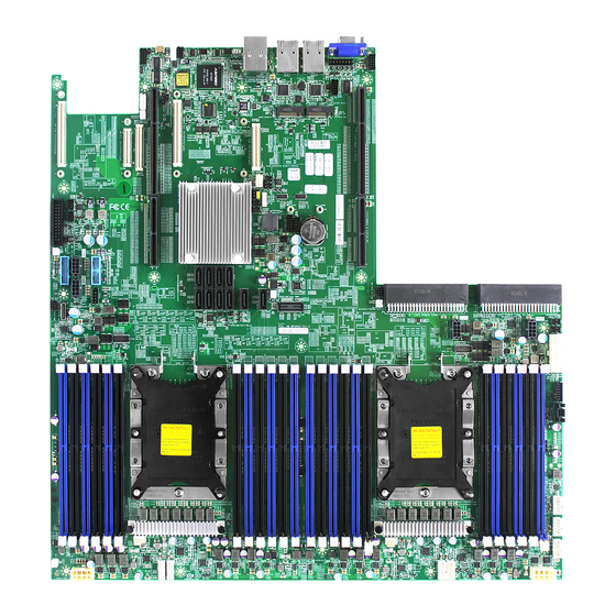
Lynx User Manual Chapter 2. Hardware Setup 3�3 Motherboard Layout 29b 30b 54 55 56 57 CPU1 JDIMMJ1 JDIMMJ 0 JDIMMK0 JDIMML1 JDIMML0 JDIMMC0 JDIMMC1 JDIMMB0 SATA6 JDIMMB1 JDIMMA0 SATA5 JDIMMA1 24 DIMM Sockets SATA4 SATA10 SATA3 SATA9 SATA2 SATA8... -
Page 26: 3�4 Connector And Jumper
Lynx User Manual Chapter 2. Hardware Setup 3�4 Connector and Jumper 3a Backplane Power Header (JPWR1) 3b Backplane Power Header (JPWR2) 3c Backplane Power Header (JPWR3) 3d Backplane Power Header (JPWR4) 4 Power Supply Connector (JPWR5) 6 Power Supply Header (JPMBUS_PDB) - Page 27 Lynx User Manual Chapter 2. Hardware Setup 8a Fan Connector (J19) 8e Fan Connector (J26) 8b Fan Connector (J20) 8f Fan Connector (J27) 8c Fan Connector (J23) 8g Fan Connector (J28) 8d Fan Connector (J25) +12V TACH FAN_PRSNT_N LED_FAN_FAULT 9a Power Supply Connector: 12V (JPWR6)
- Page 28 Lynx User Manual Chapter 2. Hardware Setup 14 Front I/O USB 2.0 Header (JUSB20) 15 OCulink Connector (JSYS_EXT) BMC GPIO Header (JBMC_GPIO1) BMC GPIO Header (JBMC_GPIO2) GPIOP3 GPIOP2 GPIOI3 GPION7 +3.3V_DUAL...
- Page 29 Lynx User Manual Chapter 2. Hardware Setup 17 Front Panel Header ( JFRNT_SSI PCH SGPIO Header (JSGPIO) 20 PCH SSGPIO (JSSGPIO)
- Page 30 Lynx User Manual Chapter 2. Hardware Setup COM Port (JCOM1) COM Port (JCOM4) 23 BMC Debug Port Header (JBMC_DP) BMC_UART_TXD5 BMC_UART_RXD5 24 Buzzer Header (JBUZZER) BMC_BUZZER- 25 LCM Header (JLCM) SW_PWR_BTN# SW_RST_BTN# TXDC RXDC HFI Header (JHFI1/JHFI2) SMB_HFI0CPU0_LVC2_SCL FM_MODPRST_HFI0_CPU0_LVT2_N SMB_HFI0CPU0_LVC2_SDA...
- Page 31 Lynx User Manual Chapter 2. Hardware Setup HFI Header (JHFI2) SMB_HFI0CPU1_LVC2_SCL FM_MODPRST_HFI0_CPU1_LVT2_N SMB_HFI0CPU1_LVC2_SDA LED_HFI0_CPU1_N RST_HFI0_CPU1_LVT2_N IRQ_HFI0_CPU1_LVT2_N SMB_HFI1CPU1_LVC2_SCL FM_MODPRST_HFI1_CPU1_LVT2_N SMB_HFI1CPU1_LVC2_SDA LED_HFI1_CPU1_N RST_HFI1_CPU1_LVT2_N IRQ_HFI1_CPU1_LVT2_N +12V +3.3V PVPP_GHI_GD +3.3V PVPP_GHI SMB_3V3SB_CLK SMB_3V3SB_DAT 33 IPMB Header (JBMC_I2C1) I2C1SDA I2C1SCL N.C. 39 BMC I2C10 Header (JBMC_I2C10)
- Page 32 Lynx User Manual Chapter 2. Hardware Setup 45 VGA Header (JVGA_INT) DACROA N.C. DACGOA DDC_DATAO DACBOA AHSYNCO N.C. DVO_5V AVSYNCO DDC_CLKO 46 SATA DOM Power Header (JDOM_PWR) +12V 47 VRM SMB Header (JSMB_VR) SMB_VR_DAT SMB_VR_CLK 51 VROC KEY BOX Header (JRAID_KEY) +3.3V_DUAL...
- Page 33 Lynx User Manual Chapter 2. Hardware Setup 58 PCIE Hot-Plug SMB Header (JPCIE_HP) CPU1_HP_I2C_CLK CPU0_HP_I2C_CLK CPU1_HP_I2C_DAT CPU10_HP_I2C_DAT +3.3V Power Supply Connector (J9) Power Supply Connector (J10) +12V +12V +12V +12V +12V +12V +12V +12V +12V +12V +12V +12V +12V +12V...
- Page 34 Lynx User Manual Chapter 2. Hardware Setup 34 BMC Disable Jumper (JBMC_DIS) BMC Disable Jump Setting JBMC_DIS Setting Short Disable (Default) Open Normal 35 BMC Reset Jumper (JBMC_RST) BMC Reset Jump Setting JBMC_RST Setting Short Reset BMC (Default) Open Normal...
-
Page 35: 3�5 System Led Indicator
Lynx User Manual Chapter 2. Hardware Setup 3�5 System LED Indicator 3�5�1 Internal LED JDIMMJ0 JDIMMK1 NGFF2 ACT LED JDIMML0 JDIMMC0 JDIMMC1 NGFF1 ACT LED JDIMMB0 JDIMMB1 UID LED UID LED JDIMMA1 RSMRST PG LED RSMRST PG LED SYSTEM PG LED... -
Page 36: Chapter 4. Bios Configuration Settings
Chapter 4. BIOS Configuration Settings Lynx User Manual Chapter 4. BIOS Configuration Settings This chapter demonstrates how to configure the UEFI BIOS settings in your system device. You can enter the BIOS screen during system startup. To enter BIOS configuration settings, •... -
Page 37: 4�2 Bios Menu
Lynx User Manual Chapter 4. BIOS Configuration Settings 4�2 BIOS Menu Press and to select the options of the menu bar. Press Enter to access the option screen. Menu Description Displays system information such as CPU bus speed, system memory speed, total installed Main memory, current EFI language, and system date &... - Page 38 Lynx User Manual Chapter 4. BIOS Configuration Settings Step 2 There will be a message “Entering SETUP” displayed on the diagnostics screen. Step 3 Identify the BIOS version. CAUTION For the official released version, the last digit of the BIOS version must end in a “0.“...
- Page 39 Lynx User Manual Chapter 4. BIOS Configuration Settings Step 4 Load Optimal Default Setting. Step 5 Save the setting and exit the BIOS setup utility.
-
Page 40: Update
Lynx User Manual Chapter 4. BIOS Configuration Settings 4�2�3 Update To identify the latest BIOS version, please check the BIOS setup. - Page 41 Lynx User Manual Chapter 4. BIOS Configuration Settings Update BIOS by INSYDE H2OFFT-D utility under DOS environment If you need to update Flash in the DOS environment, please use H2OFFT-D utility. To use this utility, you must include the flash.bat , H2OFFT-D.exe, and bin file in the same folder.
-
Page 42: 4�3 Main
Lynx User Manual Chapter 4. BIOS Configuration Settings 4�3 Main Main Option Key: 4�3�1 Main Option Key Description System time Configures the current time. System date Configures the current date. -
Page 43: 4�4 Advanced
Lynx User Manual Chapter 4. BIOS Configuration Settings 4�4 Advanced Advanced Option Key: 4.4.1 Boot Configuration Boot Configuration Numlock SCU Resolution 640*480 800*600 1024*768 Auto CSM on Enable Disable Demand USB BIOS Support USB BIOS Enable Disable UEFI Only Support... -
Page 44: 4.4.2 Peripheral Configuration
Lynx User Manual Chapter 4. BIOS Configuration Settings 4.4.2 Peripheral Configuration Peripheral Configuration PCIe SR-IOV Enable Disable PCIe ARI Enable Disable ARI Forward Enable Disable Spread Enable Disable Spectrum 4.4.3 Video Configuration Video Configuration Display Mode Plug In First On Board First 4�4�4 ACPI Table/Features Control... - Page 45 Lynx User Manual Chapter 4. BIOS Configuration Settings EMCA MCE-SMI EMCA gen 1 Dual EMCA gen 2 - Disable Enable Mode MSMI Corrected Error eLog Enable Disable eMCA Settings Memory Error eLog Enable Disable Processor Error eLog Enable Disable WHEA Support...
- Page 46 Lynx User Manual Chapter 4. BIOS Configuration Settings IIO/PCH Global Error Enable Disable Support IIO MCA Support Enable Disable IIO Error Pin Programming Enable Disable IIO Error Registers Clear Enable Disable IIO LER Support Enable Disable LER MA Error Logging...
-
Page 47: Debug Configuration
Lynx User Manual Chapter 4. BIOS Configuration Settings PCIE AER Corrected Enable Disable Errors PCIE AER Advisory Enable Disable Nonfatal Error PCIE AER Nonfatal Error Enable Disable PCIe Error PCIE AER Fatal Error Enable Disable Enabling SERR Propagation Enable Disable... -
Page 48: Socket Configuration
Lynx User Manual Chapter 4. BIOS Configuration Settings Serial Port D Auto Enable Disable Base I/O Address Interrupt IRQ7 IRQ10 4�4�9 Socket Configuration Socket Configuration Hyper-Threading Enable Disable [ALL] Check CPU BIST Enable Disable Result 3StrikeTimer Enable Disable Fast String... - Page 49 Lynx User Manual Chapter 4. BIOS Configuration Settings Core Disable Min=0x0, Max=0xfffffff Bitmap(Hex) CPU Socket IOT Cfg Enable Disable Processor 0/1/2/3 Configuration Num of OCLA Configuration Min=0, Max=8 Ways OCLA Tor IDs Min=0, Max=17 MMCFG Size 128M 256M 512M MMIO High Base...
- Page 50 Lynx User Manual Chapter 4. BIOS Configuration Settings Auto RdCur for XPT Enable Prefetch Disable Maximun UPI VNA Credit Minimun Override Per Link Auto CRC Mode 16 Bit CRC 32 Bit rolling CRC UPI Load Board for Enable Disable Failed Links...
- Page 51 Lynx User Manual Chapter 4. BIOS Configuration Settings Halt at UPI Link Train Auto Enable Disable Failure UPI Max Init Auto Enable Disable Abort Llc Share Auto Enable Disable Drd Crd Auto Mode 0 Mode 1 CBo Bias Fwd Mode...
- Page 52 Lynx User Manual Chapter 4. BIOS Configuration Settings Multi- Threaded Auto Enable Disable SPD CRC Auto Enable Disable Check Enhanced Log Enable Disable Parsing LRDIMM Auto Disable Module Delay Mem Test Auto Enable Disable Mem Test Min=0, Max=65535 Loops UDIMMs and...
- Page 53 Lynx User Manual Chapter 4. BIOS Configuration Settings WR CRC feature Auto Enable Disable Control DIMM Isolation Auto Enable Disable Enable Scrambling Min=0, Max=65535 Seed Low Scrambling Min=0, Max=65535 Seed High Enable ADR Enable Disable Legacy ADR Enable Disable Mode...
- Page 54 Lynx User Manual Chapter 4. BIOS Configuration Settings Volatile Memory Auto Mode Auto 64B Target 1LM Memory Interleave 64B Channel Granularity 256B Target 256B Channel 1-way 2-way Auto Interleaving Interleave Interleave Memory Map Auto 1-way Interleave Channel Interleaving 2-way Interleave...
- Page 55 Lynx User Manual Chapter 4. BIOS Configuration Settings Patrol Scrub Min=0, Max=24 Interval Memory RAS Configuration Patrol Scrub System Physical Setup Address Reverse Address Address Mode Set TDP DIMM power limit Auto ARS on Boot Enable Disable Auto Lock NGN CSRs...
- Page 56 Lynx User Manual Chapter 4. BIOS Configuration Settings NGN DIMM DIMM Auto BIOS Setup Management Management Driver Load NGN DIMM Auto Enable Disable Management Drivers Persistent Memory Memory Dfx Memory Auto Enable Disable Configuration Configuration Mode NVMDIMM Enable Disable Partitioning...
- Page 57 Lynx User Manual Chapter 4. BIOS Configuration Settings PCIE Coherent PCIRd Cur Setting, PRd Setting Read Partial PCIE Coherent PCIRd Cur Setting, PRd Setting Read Full PCI-E Completion Timeout (Global) Per-port Disable PCI-E Global 50m~64s Timeout Value PCI-E ASPM Per-port...
- Page 58 Lynx User Manual Chapter 4. BIOS Configuration Settings IIO IOAPIC Stack Enable Disable Intel® VT for Enable Disable Directed I/O (VT-d) Interrupt Enable Disable Remapping Intel® VT for PassThrough DMA Enable Disable Directed I/O (VT-d) Enable Disable Posted Interrupt Enable...
-
Page 59: 4.4.10 Me Configuration
Lynx User Manual Chapter 4. BIOS Configuration Settings Intel® AIC Retimer/AIC Enable Disable SSD HW at PStack0~2 Intel® AIC Intel® AIC Port A Retimer/AIC SSD Retimer/ Port B Technology (non- AIC SSD on Enable Disable Port C VMD) Socket 0~1... - Page 60 Lynx User Manual Chapter 4. BIOS Configuration Settings Enable Pre- DramInitDone None ME Reset HMRFPO_LOCK Enable Disable Message HMRFPO_ENABLE Enable Disable Message END_OF_POST Enable Disable Message HECI-1 Enable HECI-2 Enable Enable Disable HECI-3 Enable Boot Mode Override None Performance Optimized...
-
Page 61: Pch Configuration
Lynx User Manual Chapter 4. BIOS Configuration Settings 4�4�11 PCH Configuration PCH Configuration DCI enable Enable Disable (HDCIEN) DCI Auto Detect Enable Disable Enable PCH Server Error Reporting Mode Enable Disable (SERM) CLKRUN# logic Enable Disable Serial IRQ Mode Queit... - Page 62 Lynx User Manual Chapter 4. BIOS Configuration Settings SATA Controller Enable Disable Configure SATA as AHCI RAID SATA test mode Enable Disable Support Aggressive Enable Disable Link Power Management Port .~7 Enable Disable SATA Port 0 Enable Disable DevSlp Hot Plug...
- Page 63 Lynx User Manual Chapter 4. BIOS Configuration Settings sSATA Controller Enable Disable Configure SATA as AHCI RAID SATA test mode Enable Disable Support Aggressive Enable Disable Link Power Management Port 0~5 Enable Disable Hot Plug Enable Disable Configure as Enable...
- Page 64 Lynx User Manual Chapter 4. BIOS Configuration Settings USB Precondition Enable Disable XHCI Manual Mode Enable Disable Trunk Clock Gating Enable Disable (BTCG) Enable USB 3.0 Enable Disable pins USB 3.0 pin Enable Disable #1~#10 USB Per-Connector Enable Disable Disable...
- Page 65 Lynx User Manual Chapter 4. BIOS Configuration Settings MCTP Broadcast Enable Disable Cycle DMI Link Down Hang Bypass Enable Disable (DLDHB) Enable/ Platform-POR Enable Disable Disable ADR ADR GPIO GPIO B GPIO C Enable/ Disable ADR Platform-POR Enable Disable Timer...
-
Page 66: H2O Ipmi Configuration
Lynx User Manual Chapter 4. BIOS Configuration Settings 4�4�12 H2O IPMI Configuration H2O IPMI Configuration IPMI Support Enable Disable BMC Warmup Min=0, Max=240 Time ACPI SPMI Enable Disable Table Boot Option Enable Disable Support Set BIOS Enable Disable version to BMC... -
Page 67: Console Redirection Setup
Lynx User Manual Chapter 4. BIOS Configuration Settings 4�4�14 Console Redirection Setup Console Redirection Setup Console Serial Enable Disable Redirect Terminal Type VT_100 VT_100+ VT_UTF8 PC_ANSI Baud Rate 1200 2400 4800 9600 19200 38400 57600 115200 Data Bits 7 Bits... -
Page 68: 4�5 Security
Lynx User Manual Chapter 4. BIOS Configuration Settings 4�5 Security Security Option Key: 4�5�1 Security Security Current TPM Not Detected TPM 1.2 TPM 2.0 Device TPM Availability Available Hidden TPM Operation No operation Disable and Deactivate Enable and Activate Clear TPM... -
Page 69: 4�6 Power
Lynx User Manual Chapter 4. BIOS Configuration Settings 4�6 Power Power Option Key: 4�6�1 Power Power Wake on PME Enable Disable Auto Wake on S5 By Every day By Day of Month Disable Wake on S5 Time HH(0):MM(0):SS(0) Day of Month... -
Page 70: 4�7 Boot
Lynx User Manual Chapter 4. BIOS Configuration Settings 4�7 Boot Boot Option Key: 4�7�1 Boot Boot Boot Type Dual Boot Type Legacy Boot Type UEFI Boot Type Quick Boot Enable Disable Quiet Boot Enable Disable Network Stack Enable Disable PXE Boot to LAN... -
Page 71: 4�8 Exit
Lynx User Manual Chapter 4. BIOS Configuration Settings 4�8 Exit Exit Option Key: 4�8�1 Exit Save and Exit Exit Saving Changes Exit system setup and save your changes. Save Change Without Save your changes without exiting the system. Exit Exit Discarding Discard your changes when existing the system. -
Page 72: Chapter 5. Bmc Configuration Settings
Chapter 5. BMC Configuration Settings Lynx User Manual Chapter 5. BMC Configuration Settings 5�1 Login NOTE This feature works with the JAVA 6 run time installed console environment. The IP address below is an example using the default IP setting. The IP address is configurable. -
Page 73: 5�2 Web Gui
Lynx User Manual Chapter 5. BMC Configuration Settings 5�2 Web GUI 5�2�1 Menu Bar Click to select the options of the menu bar. Menu Description The Dashboard page gives the overall information about the status of a Dashboard device. Sensor The Sensor Readings page displays all the sensor related information. -
Page 74: User Information And Quick Button
Lynx User Manual Chapter 5. BMC Configuration Settings 5�2�2 User Information and Quick Button The user information and quick access buttons are located at the top right corner. It displays the logged-in user, his/her privilege and the four quick buttons allowing you to perform different functions. -
Page 75: Dashboard
Lynx User Manual Chapter 5. BMC Configuration Settings 5�2�3 Dashboard The Dashboord page displays device, system, and network information. Click Dashboard on the menu bar to view the overall information of the server. 5�2�4 Sensor The Sensor page displays the status and records on related sensors. -
Page 76: Fru Information
Lynx User Manual Chapter 5. BMC Configuration Settings 5�2�5 FRU Information The FRU Information page displays Basic Information, Chassis Information, Board Information and Product Information of the FRU device. Click FRU Information on the menu bar to view the details of the selected device. -
Page 77: Logs And Reports
Lynx User Manual Chapter 5. BMC Configuration Settings 5�2�6 Logs and Reports The System Inventory page displays IPMI Event Log and Video Log. Click Logs and Reports from the menu bar → select Event Log or Video Log to view the contents. -
Page 78: Settings
Lynx User Manual Chapter 5. BMC Configuration Settings 5�2�7 Settings The Settings page displays the configuration settings for KVM Mouse Setting, Media Redirection Settings, Network Settings, Platform Event Filter, Services, SMTP Settings, SSL Settings, System Firewall, User Management, and Video Recording. - Page 79 Lynx User Manual Chapter 5. BMC Configuration Settings Settings Menu and Option Keys: Settings Mouse Mode Configuration • Relative Positioning (Linux) KVM Mouse Setting • Absolute Positioning (Windows) • Other Mode (SLES-11 OS Installation) Media Redirection VMedia Instance General Settings...
-
Page 80: Remote Control
Lynx User Manual Chapter 5. BMC Configuration Settings 5�2�8 Remote Control The Remote Control page displays the configuration for power control and remote KVM. Launch KVM... - Page 81 Lynx User Manual Chapter 5. BMC Configuration Settings Procedure To Start KVM Step 1 Click Start KVM to start the H5Viewer video redirection. Step 2 Click Browse to select CD Image. Step 3 Click Start Media to redirect the selected CD image file to the Host.
- Page 82 Lynx User Manual Chapter 5. BMC Configuration Settings Remote KVM Menu and Option Key Button Description Start KVM Starts the H5Viewer video redirection. Stop KVM Stops the H5Viewer video redirection. Pause Video This option is used for pausing Console Redirection.
- Page 83 Lynx User Manual Chapter 5. BMC Configuration Settings This menu item can be used to act as the right- Right <Ctrl> side <CTRL> key when in Console Redirection. This menu item can be used to act as the right- Right <Alt>...
-
Page 84: Power Control
Lynx User Manual Chapter 5. BMC Configuration Settings 5�2�9 Power Control The Power Control page allows you to view and control the power of your server. To open Power Control, click Power Control from the menu bar. The various options of Power Control are given below. -
Page 85: Maintenance
Lynx User Manual Chapter 5. BMC Configuration Settings 5�2�10 Maintenance This Maintenance page displays the configuration settings for Backup Configuration, Firmware Image Location, Firmware Information, Fimware Update, Preserve Configuration, Restore Configuration, Restore Configuration, and Restore Factory Defaults. - Page 86 Lynx User Manual Chapter 5. BMC Configuration Settings Maintenance Procedure 1. Click Check All to backup the selected configuration items. The Backup Configuration page will appear Click Download Config to save the backup file to the client system Backup Configuration 2.
-
Page 87: Sign Out
Lynx User Manual Chapter 5. BMC Configuration Settings 5�2�11 Sign out To log out of the BMC: Method 1: Click Sign out from the menu bar. The Logout dialog box will pop out. Method 2: Click the root quick button on the top right corner of the screen. -
Page 88: 5�3 Firmware Update
1. Boot to the DOS (MS-DOS or Free DOS is workable). 2. Enter BMC firmware directory [XXXXXLXOOOYYY_ARK]; XXXXX: project name ; OOO: for Lynx standard version YYY:firmware version; K: For auxiliary version 3. Execute a�bat batch file to update the BMC firmware. -
Page 89: Chapter 6� Technical Support
Chapter 6� Technical Support Taiwain, Global Headquarters South California, United States Address: No. 152, Section 4, Address: 21808 Garcia Lane Linghang N� Rd, Dayuan District, City of Industry, CA 91789, Taoyuan City 337, Taiwan United States Tel: +886-3-433-9188 Toll free: +7-4997019998 Fax: +886-3-287-1818 Tel: +1-909-895-8989 Sales Email: sales@aicipc�com�tw...
Need help?
Do you have a question about the Lynx and is the answer not in the manual?
Questions and answers