Table of Contents
Advertisement
Quick Links
Advertisement
Table of Contents

Related Manuals for AIC Auriga


Summary of Contents for AIC Auriga
- Page 1 Auriga Server Motherboard User's Manual UM_Auriga_v1_103118...
-
Page 2: Table Of Contents
Table of Contents Preface ��������������������������������������������������������������������������������������������������������� i Safety Instructions �������������������������������������������������������������������������������������� ii About This Manual �������������������������������������������������������������������������������������� iii Chapter 1� Product Features ����������������������������������������������������������������������1 1�1 Component ���������������������������������������������������������������������������������������1 1.2 Specifications �����������������������������������������������������������������������������������2 1�3 Feature ���������������������������������������������������������������������������������������������3 Chapter 2� Hardware Setup ������������������������������������������������������������������������4 2�1 Central Processing Unit Setup ����������������������������������������������������������4 2.1.1 Processor Installation ..................4 2�2 System Memory Setup ����������������������������������������������������������������������7 2.2.1 DIMM Installation ....................7... - Page 3 4�3 Main ����������������������������������������������������������������������������������������������24 4.3.1 Main ........................24 4�4 AMD CBS ����������������������������������������������������������������������������������������25 4.4.1 Zen Common Options ..................25 4.4.2 DF Common Options ..................26 4.4.3 UMC Common Options ..................26 4.4.4 NBIO Common Options ................... 29 4.4.5 FCH Common Options ..................29 4�5 Advanced ���������������������������������������������������������������������������������������30 4.5.1 Demo Board .....................
- Page 4 5�1 Login ����������������������������������������������������������������������������������������������38 5�2 Web GUI ������������������������������������������������������������������������������������������39 5.2.1 Menu Bar ......................39 5.2.2 User Information and Quick Button ............... 40 5.2.3 Dashboard ......................41 5.2.4 Sensor ......................41 5.2.5 FRU Information ....................42 5.2.6 Logs and Report ....................43 5.2.7 Settings ......................44 5.2.8 Remote Control ....................
- Page 5 Document Release History Release Date Version Update Content October User's Manual release to public. 2018 Contents...
- Page 6 Copyright © 2018 AIC, Inc. All Rights Reserved. This document contains proprietary information about AIC products and is not to be disclosed or used except in accordance with applicable agreements.
-
Page 7: Preface
Disclaimer AIC shall not be liable for technical or editorial errors or omissions contained herein. The information provided is provided "as is" without warranty of any kind. To the extent permitted by law, neither AIC or its affiliates, subcontractors or suppliers will be liable for incidental, special or consequential damages including downtime cost;... -
Page 8: Safety Instructions
Safety Instructions When installing, operating, or performing maintenance on this equipment, the following safety precautions should always be taken into account in order to reduce the risk of fire, electric shock, and personal injury. Carefully read the safety instructions below before using this product. •... -
Page 9: About This Manual
This document pellucidly presents a brief overview of the product design, device installation, and firmware settings for the Auriga motherboard. For the latest version of this user's manual, please refer to the AIC website: http://www.aicipc.com/tw/productdetail/50944. -
Page 10: Chapter 1� Product Features
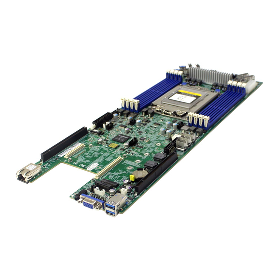
Chapter 1� Product Features Spica User Manual Auriga User Manual Chapter 1. Product Features This section describes the hardware specifications and features of the Auriga motherboard. The fundamental components of the Auriga severboard are provided below. 1�1 Component Auriga Serverboard Socket SP3 (Single AMD EPYC™... -
Page 11: 1.2 Specifications
Auriga User Manual Chapter 1. Product Features 1.2 Specifications Processor Aspeed AST2500 Advanced PCIe Graphics & Single AMD EPYC™ 7000-series Support Remote Management Processor • Baseboard Management Controller 180W CPU TDP • Intelligent Platform Interface 2.0 (IPMI 2.0) • iKVM, Media Redirection, IPMI over LAN,... -
Page 12: 1�3 Feature
Chapter 1. Product Features 1�3 Feature The Auriga server board integrates AMD EPYC™ 7000-series processor and 8 channel DDR4 memory slots to offer support for greater capacity, durability, and proficiency for our customers. Featuring the AMD EPYC™ 7000-series processor as the core design of the serverboard, which is emphasized for its outstanding performance, great memory bandwidth, and high security based on “Zen”... -
Page 13: Chapter 2� Hardware Setup
Chapter 2� Hardware Setup Chapter 2. Hardware Setup Auriga User Manual This section describes a simple instruction guide for installing the hardware components on the serverboard system. Turn off and unplug all system and peripheral devices before proceeding. 2�1 Central Processing Unit Setup The serverboard supports a single AMD EPYC™... - Page 14 Auriga User Manual Chapter 2. Hardware Setup Step 2 Lift the carrier frame by the blue metal tab and remove the protective cover as demonstrated in figure 3 and figure 4. Figure 3 Lift carrier frame Figure 4 Remove protective cover...
- Page 15 Chapter 2. Hardware Setup Auriga User Manual Step 5 Close the carrier frame with the CPU package as demonstated in figure 7. Check if the frame is properly installed as demonstrated in figure 8. Figure 7 Close carrier frame Figure 8 Verify installation...
-
Page 16: 2�2 System Memory Setup
Auriga User Manual Chapter 2. Hardware Setup 2�2 System Memory Setup This server board supports 8 DIMM memory slots with 1 DIMM per channel. 2�2�1 DIMM Installation Step 1 Unlock the DIMM socket by pressing the retaining clips outward. Step 2 Insert the memory module into the slot. Make sure that the DIMM notch is accurately positioned. -
Page 17: Dimm Location
Chapter 2. Hardware Setup Auriga User Manual 2�2�2 DIMM Location The DIMMs are displayed on the Aurigaboard as JDMA0, JDMB0, JDMC0, JDMD0, JDME0, JDMF0, JDMG0, JDMH0 as demonstrated. JDMA0 and JDME0 are the located nearest to the CPU. To ensure satisfactory performance, you need to: ... -
Page 18: Chapter 3� Motherboard Settings
Auriga User Manual Chapter 3. Motherboard Settings This section provides illustrations that display the internal jumpers, connectors, and system LED indicators on the Auriga motherboard. The motherboard layout and essential connectors are listed below for your reference. 3�1 Block Diagram... -
Page 19: 3�2 Content List
Auriga User Manual Chapter 3. Motherboard Settings 3�2 Content List Connector/Jumper/Header Location Connector/Jumper/Header Location JG0FR1, JG0FR2 JG1FR1, JG1FR2 Battery Socket (For PCIe Bus JBAT1 JG2FL1, JG2FL2 CR2032) JG3FL1, JG3FL2 JFAN1, JFAN2, FAN connector 25 Clear CMOS JCMOS1 JFAN3, JFAN4 JTHM1, JTHM2... -
Page 20: 3�3 Connector And Jumper Location
Auriga User Manual Chapter 3. Motherboard Settings 3�3 Connector and Jumper Location CPU0 A2 A1 K A2 A1 K... - Page 21 Auriga User Manual Chapter 3. Motherboard Settings 2a FAN Header (JFAN1) 4 PMBUS I2C Header (JPMBUS1 ) FANTACH_2 1 2 FANTACH_1 1 SMB_PMBUS_CLK +12V_S0 3 4 +12V_S0 2 SMB_PMBUS_DATA SYS1_FAN_PWM_C 5 6 SYS1_FAN_PWM_C 3 PMBUS_ALERT_N 7 8 GND 4 GND...
- Page 22 Auriga User Manual Chapter 3. Motherboard Settings 11 a SATA-DOM Power Header (JSATA1_PWR2 ) 17 GPIO Header (JBMC_GPIO1) 1 GND RACK_EXTRST_N 1 GND BMC_GPY1 3 BMC_I2C_09_SDA 2 DOM_PWR1 BMC_GPY0 5 BMC_I2C_09_SCL 3 +5V_S0_SATA1 Jumper default PIN-1 & PIN-2 18 Debug Port Header (JLPC1)
- Page 23 Auriga User Manual Chapter 3. Motherboard Settings 36 Front panel Header for RACK (JRACK1) 42 BMC COM2 Header (JCOM1) RACK_EXTRST_N 2 BMC_I2C_08_SCL DCDB 1 DSRB RXDB 3 RTSB 4 BMC_I2C_08_SDA TXDB 5 CTSB BMC_I2C_01_SCL 6 GND DTRB 7 RIB BMC_I2C_01_SDA...
- Page 24 Auriga User Manual Chapter 3. Motherboard Settings A2 A1 K A2 A1 K 25 SOC CMOS Clean Header(JCMOS1) 28 Front VGA Header (JVGA2) 1 +VDDBT_RTC_JP DACROA 1 GND (CR2032) 3 DACGOA 2 +1V5_RTC (SOC) 5 DDC_DATAO 3 GND DACBOA 7 GND Jumper default PIN-1 &...
-
Page 25: 3�4 System Led Indicator
Auriga User Manual Chapter 3. Motherboard Settings 3�4 System LED Indicator 3�4�1 Rear Panel LED Cable Link/Active Status: 1. Cable Plug-In : Green Green LAN1 (Right, JLAN1 Pin-13,14) 2. Cable Plug-Out : Off 1. 1Gbps : Green Linking Speed: Green, 2. -
Page 26: Led Indicator Location
Auriga User Manual Chapter 3. Motherboard Settings 3�4�3 LED Indicator Location LED1 LED1 LED2 LED2 LED3 LED3 LED4 LED5 LED4 LED5 LED7 LED6 LED7 LED6 JLAN1 A2 A1 K A2 A1 K Pin-13, 14 LED 8 Pin-15, 16... -
Page 27: Chapter 4. Bios Configuration Settings
Chapter 4. BIOS Configuration Settings Auriga User Manual Chapter 4. BIOS Configuration Settings This chapter demonstrates how to configure the UEFI BIOS settings in your system device. You can enter the BIOS screen during system startup. To enter BIOS configuration settings, •... -
Page 28: 4�2 Bios Setup
Auriga User Manual Chapter 4. BIOS Configuration Settings 4�2 BIOS Setup 4�2�1 BIOS Menu Press and to select the options of the menu bar. Press Enter to access the option screen. Menu Description Main Displays system information such as CPU bus speed, system memory speed, total installed memory, current EFI language, and system date &... - Page 29 Auriga User Manual Chapter 4. BIOS Configuration Settings Step 2 There will be a message “Entering SETUP” displayed on the diagnostics screen. Step 3 Identify the BIOS version.
- Page 30 Auriga User Manual Chapter 4. BIOS Configuration Settings Step 4 Load Optimal Default Setting. Step 5 Save the setting and exit the BIOS setup utility.
-
Page 31: Bios Update
Auriga User Manual Chapter 4. BIOS Configuration Settings 4�2�3 BIOS Update To identify the latest BIOS version, please check the BIOS setup. - Page 32 Auriga User Manual Chapter 4. BIOS Configuration Settings Update BIOS by INSYDE H2OFFT-D utility under DOS environment If you need to update Flash in the DOS environment, please use H2OFFT-D utility. To use this utility, you must include the flash.bat , H2OFFT-D.exe, and bin file in the same folder.
-
Page 33: 4�3 Main
Auriga User Manual Chapter 4. BIOS Configuration Settings 4�3 Main 4�3�1 Main Main Option Key: Option Key Description Language Configures the language used for your BIOS settings. System time Configures the current time. System date Configures the current date. -
Page 34: 4�4 Amd Cbs
Auriga User Manual Chapter 4. BIOS Configuration Settings 4�4 AMD CBS AMD CBS Option Key: 4�4�1 Zen Common Options Zen Common Options Core Performance Auto Disable Boost Global C-state Auto Enable Disable Control Global C-state Min=0x1,Max=0x10 Control Two (1+1) Two (2+0) -
Page 35: Df Common Options
Auriga User Manual Chapter 4. BIOS Configuration Settings 4�4�2 DF Common Options DF Common Options Memory None Channel Socket Auto interleaving Memory Auto interleaving 4�4�3 UMC Common Options UMC Common Options I Decline Auto Overclock Enabled Auto 333 MHz 400 MHz... - Page 36 Auriga User Manual Chapter 4. BIOS Configuration Settings Activate Delay TrrdL Time, same bank group Auto Tfaw Ctrl Manual Min=0x6 Tfaw Max=0x36 Minimum Write to Read Time, TwtrS different bank group Minimum Write to TwtrL Read Time, same bank group...
- Page 37 Auriga User Manual Chapter 4. BIOS Configuration Settings ProcODT Processor ODT Minimum CAS Tcwl Write Latency Range Read to Precharge Trtp Delay Trdwr tWRTTO time. Read delay Twrrd when accessing different DIMMs. DDR4 Common DRAM Timing I Accept Options Configuration...
-
Page 38: Nbio Common Options
Auriga User Manual Chapter 4. BIOS Configuration Settings 4�4�4 NBIO Common Options NBIO Common Options Determinism Slider Auto Power Performance cTDP Control Auto Manual Auto NB Configuration IOMMU Enable Disable 4�4�5 FCH Common Options FCH Common Options Always off Always on... -
Page 39: 4�5 Advanced
Auriga User Manual Chapter 4. BIOS Configuration Settings 4�5 Advanced Advanced Option Key: 4�5�1 Demo Board Demo Board OnBrd/Ext VGA Select Auto Onboard External 4�5�2 USB Configuration USB Configuration USB Ports Per-Port Enable Disable Disable Control USB 3.0 Port 0 USB 3.0 Port 1... -
Page 40: Cpu Related Setting
Auriga User Manual Chapter 4. BIOS Configuration Settings 4�5�3 CPU Related Setting CPU Related Setting SVM support Enable Disable SMM Code Lock Enable Disable AMD CPU SMT Support Auto Disable AMD CPU P-state Control Enable Disable 4�5�4 PCI Sub System Setting... -
Page 41: H2O Event Log Config Manager
Auriga User Manual Chapter 4. BIOS Configuration Settings Power Cycle Time Enable Disable Support Power Cycle Time Min=0, Max=255 Power Button Enable Disable Reset Button Enable Disable NMI Button Enable Disable BMC Configuration Lan Port Dedicated Shared Configuration Lan Port... -
Page 42: Console Redirection
Auriga User Manual Chapter 4. BIOS Configuration Settings Serial Debug Show Debug Configuration Pages Message Code Serial Enable Disable Configuration Message Event And Message Read only. Pages 4�5�9 Console Redirection Console Redirection Console Serial Enable Disable Redirect Terminal Type VT_100... -
Page 43: 4�6 Security
Auriga User Manual Chapter 4. BIOS Configuration Settings 4�6 Security Security Option Key: 4�6�1 Current TPM Device Current TPM Device Not detected TPM 2.0 4�6�2 TrEE Protocol Version TrEE Protocol Version 4�6�3 TPM Availability TPM Availability Available Hidden 4�6�4 TPM Operation... -
Page 44: 4�7 Power
Auriga User Manual Chapter 4. BIOS Configuration Settings 4�7 Power Disabled,By Every Day,By Day of Mo nth Power Option Key: 4�7�1 Auto Wake on S5 Auto Wake on S5 Disable By Every Day By Day of Month... -
Page 45: 4�8 Boot
Auriga User Manual Chapter 4. BIOS Configuration Settings 4�8 Boot Boot Option Key: Boot Boot Type UEFI Boot Type Legacy Boot Type Quick Boot Enable Disable Quiet boot Enable Disable Network Stack Enable Disable PXE Boot capability Enable Disable Power Up in Standby Support... -
Page 46: 4�9 Exit
Auriga User Manual Chapter 4. BIOS Configuration Settings 4�9 Exit Exit Option Key: Save and Exit Exit Saving Changes Exit system setup and save your changes. Save Change Without Exit Save your changes without exiting the system. Exit Discarding Changes Discard your changes when existing the system. -
Page 47: Chapter 5. Bmc Configuration Settings
Chapter 5. BMC Configuration Settings Auriga User Manual Chapter 5. BMC Configuration Settings This chapter displays the configuration settings of IPMI BMC in your system device. 5�1 Login NOTE This feature works with the html5. Please use a browser that supports html5. -
Page 48: 5�2 Web Gui
Auriga User Manual Chapter 5. BMC Configuration Settings 5�2 Web GUI 5�2�1 Menu Bar Click to select the options of the menu bar. Menu Description The Dashboard page gives the overall information about the Dashboard status of a device. The Sensor Readings page displays all the sensor related Sensor information. -
Page 49: User Information And Quick Button
Auriga User Manual Chapter 5. BMC Configuration Settings 5�2�2 User Information and Quick Button The user information and quick access buttons are located at the top right corner. It displays the logged-in user, his/her privilege and the four quick buttons allowing you to perform different functions. - Page 50 Auriga User Manual Chapter 5. BMC Configuration Settings 5�2�3 Dashboard The Dashboard page displays device, system information, and assert logs. Click Dashboard on the menu bar to view the overall information of the server. 5�2�4 Sensor The Sensor page displays the status and records on related sensors. Click a record to...
-
Page 51: Fru Information
Auriga User Manual Chapter 5. BMC Configuration Settings 5�2�5 FRU Information The FRU Information page displays Basic Information, Chassis Information, Board Information and Product Information of the FRU device. Click FRU Information on the menu bar to view the details of the selected device. -
Page 52: Logs And Report
Auriga User Manual Chapter 5. BMC Configuration Settings 5�2�6 Logs and Report The System Inventory page displays IPMI Event Log and Video Log. Click Logs and Reports from the menu bar and select Event Log or Video Log to view the contents. -
Page 53: Settings
Auriga User Manual Chapter 5. BMC Configuration Settings 5�2�7 Settings The Settings page displays the configuration settings for Date & Time, External User Services, KVM Mouse Setting, Log Settings, Media Redirection Settings, Network Settings, PAM Order Settings, Platform Event Filter, Services, SMTP Settings, SSL... - Page 54 Auriga User Manual Chapter 5. BMC Configuration Settings Settings Menu and Option Key: Settings Description Date and Time LDAP/E-directory Active directory Settings Radius Settings Settings External User General Advanced Services General Role General Role Radius Radius Settings Groups Settings Groups...
-
Page 55: Remote Control
Auriga User Manual Chapter 5. BMC Configuration Settings 5�2�8 Remote Control The Remote Control page displays the configuration for power control and remote KVM. Click Java Console to start the JViewer video redirection. - Page 56 Auriga User Manual Chapter 5. BMC Configuration Settings Click Launch KVM to open the Remote KVM page.
- Page 57 Auriga User Manual Chapter 5. BMC Configuration Settings Procedure to Start KVM Step 1 Click Start KVM to start the H5Viewer video redirection. Step 2 Click Browse to select CD Image. Step 3 Click Start Media to redirect the selected CD image file to the Host.
- Page 58 Auriga User Manual Chapter 5. BMC Configuration Settings Remote KVM Menu and Option Key: Remote KVM Description Start KVM Starts the H5Viewer video redirection. Stop KVM Stops the H5Viewer video redirection. Pause Video This option is used for pausing Console Redirection.
- Page 59 Auriga User Manual Chapter 5. BMC Configuration Settings This menu item can be used to act Right <Ctrl> as the right-side <CTRL> key during Console Redirection. This menu item can be used to act Right <Alt> as the right-side <ALT> key during Console Redirection.
-
Page 60: Power Control
Auriga User Manual Chapter 5. BMC Configuration Settings 5�2�9 Power Control The Power Control page allows you to view and control the power of your server. To open Power Control, click Power Control from the menu bar. The various options of Power Control are given below. -
Page 61: Chassis Identify Control
Auriga User Manual Chapter 5. BMC Configuration Settings 5�2�10 Chassis Identify Control The Chassis Identify Control page displays the BMC’s UID control information. Users can change the Identify LED behavior on this page. Click Chassis Identify Control from the menu bar. Select Off/On to control UID LED. -
Page 62: Maintenance
Auriga User Manual Chapter 5. BMC Configuration Settings Maintenance Description 1. Click Check All to backup the selected configuration items. The Backup Configuration page will appear Click Download Config to save the backup Backup file to the client system. Configuration 2. -
Page 63: Sign Out
Auriga User Manual Chapter 5. BMC Configuration Settings 5�2�12 Sign out To log out of the BMC: Method 1: Click Sign out from the menu bar. The Logout dialog box will pop out. Cancel Method 2: Click the root quick button on the top right corner of the screen. -
Page 64: Chapter 6� Technical Support
Chapter 6� Technical Support Taiwain, Global Headquarters South California, United States Address: No� 152, Section 4, Address: 21808 Garcia Lane Linghang N� Rd, Dayuan District, City of Industry, CA 91789, Taoyuan City 337, Taiwan United States Tel: +886-3-433-9188 Toll free: +7-4997019998 Fax: +886-3-287-1818 Tel: +1-909-895-8989 Sales Email: sales@aicipc�com�tw...
Need help?
Do you have a question about the Auriga and is the answer not in the manual?
Questions and answers