FAAC 412 Installation Instructions Manual
Operator and control panel
Hide thumbs
Also See for 412:
- Manual (57 pages) ,
- Installation manual (28 pages) ,
- Installation manual (20 pages)
Table of Contents
Advertisement
Quick Links
The 412 Operator and
450 MPS Control Panel:
Installation Manual
Important Safety Information........................................................................ 2
Technical Data .............................................................................................. 4
The 412 Compact Operator.................................................................... 4
The Control Panel .................................................................................. 4
Unpacking the Operator ................................................................................ 5
The 412 Compact Operator........................................................................... 6
General Characteristics .......................................................................... 6
Operating Logic ..................................................................................... 6
Manual Release Mechanism ........................................................... 6
General Operating Logic ................................................................ 7
Logical Operating Modes ............................................................... 7
Installation Instructions............................................................................... 10
Prepare the Gate................................................................................... 10
Install the Operator .............................................................................. 10
Attach the Rear Mounting Bracket .............................................. 10
Attach the Operator to the Rear Mounting Bracket ...................... 12
Attach the Operator to the Front Mounting Bracket ..................... 12
Attach the Front Mounting Bracket to the Gate Leaf ................... 12
Attach the Operator Cover............................................................ 13
Install the 450 MPS Control Panel...................................................... 14
Connect the Main Power Supply .................................................. 14
Connect One Activating Device ................................................... 15
Connect the Operator(s) to the Control Panel.............................. 15
Check the Motor's Direction of Rotation .................................... 17
Connect Other Devices ................................................................. 17
Set Operating Controls......................................................................... 20
Set DIP Switches .......................................................................... 20
Adjust the Potentiometers ............................................................. 20
Maintenance ................................................................................................ 21
The 412 Operator ................................................................................. 21
The Control Panel ................................................................................ 21
Troubleshooting .......................................................................................... 22
FAAC International, Inc.
303 Lexington Avenue
Cheyenne, WY 82007
Contents
Advertisement
Table of Contents

Related Manuals for FAAC 412


Summary of Contents for FAAC 412
-
Page 1: Table Of Contents
450 MPS Control Panel: Installation Manual Contents Important Safety Information................ 2 Technical Data ....................4 The 412 Compact Operator..............4 The Control Panel .................. 4 Unpacking the Operator ................5 The 412 Compact Operator................6 General Characteristics ................6 Operating Logic ..................6 Manual Release Mechanism ............ -
Page 2: Important Safety Information
Important Safety Information Both the installer and the owner and/or operator of Gate Design this system need to read and understand this 1. A gate is a potential traffic hazard, so it is im- installation manual and the safety instructions portant that you locate the gate far enough away supplied with other components of the gate system. - Page 3 Refer to the label on your 8. To guarantee the efficiency of this equipment, the operator system. manufacturer recommends that qualified personnel periodically check and maintain the equipment. U.L. Class and FAAC Operator Duty Cycle Typical Use Model Class I: Residential Vehicular Gate Operator •...
-
Page 4: Technical Data
Department. Note that any change in the capacitors may affect duty cycle. The 90-deg opening time for a gate with the 412 Operator is a maximum of about 46 sec. Note that both the mounting dimensions and the torque adjustment help to determine the precise opening speed. -
Page 5: Unpacking The Operator
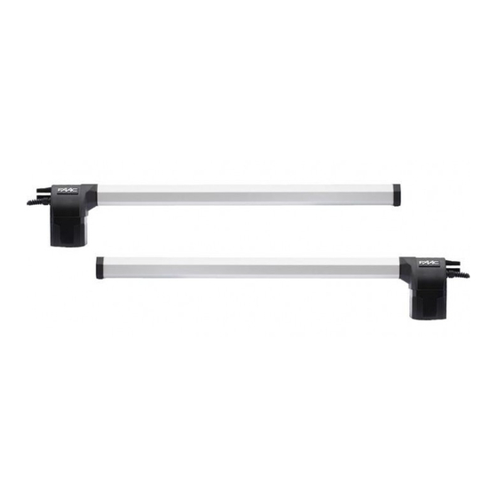
Cover Rear bracket Motor Power cable Cable cover Figure 1. Parts of the 412 Compact Operator (SX model is shown) Figure 2. Mount the proper model (SX or DX) on the gate leaf whether the gate swings inward or outward. -
Page 6: The 412 Compact Operator
The Manual Release mechanism is a built-in release right and one left version. device of the 412 Operator (see Figure 3). To access the keyhole, remove the plug on the top of the motor In two-operator gate installations, both operators are housing. -
Page 7: General Operating Logic
General Operating Logic command during closing reopens the gate. Given the electromechanical nature of the 412 Operator, • S (security): The automatic mode is like A the behavior of the operator when it encounters an... - Page 8 A (Automatic) Logic Gate Open A Open B Stop Opening Closing Warning Status Reversing Reversing Light Device(s) Device(s) Opens both leaves Opens single leaf No effect No effect No effect Closed and closes them connected to after pause time Motor 1 and closes it after pause time Opening...
- Page 9 E (Semi-automatic) Logic Gate Open A Open B Stop Opening Closing Warning Status Reversing Reversing Light Device(s) Device(s) Closed Opens both leaves Opens single leaf No effect No effect No effect connected to Motor 1 Opening Stops Stops Stops Stops; gate closes No effect when reversing device no longer...
-
Page 10: Installation Instructions
Attaching the front mounting bracket to the gate leaf Prepare the Gate • Attaching the operator’s protective cover Before you install the 412 Operator, you need to • Installing the 450 MPS control panel prepare the gate itself for the operator. Be sure to do •... - Page 11 Gate speed increases as the dimensions A and B decrease. The torque adjustment may also affect the gate speed. The sum of A and B must equal a minimum of 3 5/8 in. (9 cm). Figure 5. Important mounting dimensions for inward-swinging 412 operators, top view 11 13/16 in. mounting bracket (see Figure 6). The recessed liner (30 cm) should be constructed of 3/16 or 1/4 in.
-
Page 12: Attach The Operator To The Rear Mounting Bracket
Outward swinging gate: in the direction of the gate’s closing. If you are installing the 412 Operator to swing the gate outward, construct a steel elbow of sufficient size to attach to the gate pillar and rear mounting bracket (see You should be able to lengthen or shorten the cylinder covering the operator’s worm screw by pulling or... -
Page 13: Attach The Operator Cover
Next, you must determine that the worm screw has not dimensions are incorrect (see Figure 5 or 7, whichever reached the full extent of its travel. Remove the applies to your installation). Reattach the rear operator from the front mounting bracket and push or mounting bracket as necessary. -
Page 14: Install The 450 Mps Control Panel
WARNING! The voltage of the main power Figure 12 shows the typical layout for a two-leaf gate must match the required voltage of the 412 with two 412 Operators. Operator and the 450 MPS control panel. -
Page 15: Connect One Activating Device
J1 terminal block for main power supply Leaf delay potentiometer J2 terminal block for connecting the operator(s) DIP switch assembly J3 terminal block for low-voltage accessories Fuses 220 VAC 115 VAC J4 quick connector port F1, Main power 10 A Pressure adjustment potentiometer F2, Accessories 800 mA... - Page 16 9 10 11 12 13 14 15 16 17 18 19 20 21 22 23 24 25 Figure 14. The terminal strip wiring of the 450 MPS To the U. L. Listed gate operator U.L. Listed Control Panel Enclosure 450 MPS Control Panel Junction box U.L.Listed cord grip...
-
Page 17: Check The Motor's Direction Of Rotation
If any operator is more than 2 ft away from the U.L. Disengage the operator(s) with the Manual Release key, Listed control panel enclosure, the connection must be and open the gate by hand about halfway. made inside a junction box. Use a U. L. Listed cord grip where the operator cord enters the junction box;... - Page 18 17. If your gate has two leaves, connect the devices to terminals 18 and 19. FAAC International, Inc., strongly recommends you install reversing devices. If you choose not to install In addition, terminal block J3 requires a fail-safe such devices, then you must install the necessary connection for the transmitter of the photocells.
- Page 19 Stop Button: The stop button you install must have 11 12 13 14 15 16 17 18 19 20 21 22 23 24 25 normally closed (N.C.) contacts. Multiple stop buttons — — — — — — — must be wired in series. Connect your stop device 30 Vcc STOP FSWTX W.LIGHT...
-
Page 20: Set Operating Controls
The 450 MPS Control Panel offers six operating modes: A, S, E, EP, B, and C. B and C logic are appropriate for guard station applications of the 412 Operator. Refer to the operating logic tables earlier in these instructions for more detail. -
Page 21: Maintenance
Maintenance The 412 Operator The Control Panel The FAAC 412 Operator requires no maintenance. The control panel requires no maintenance, but every six months you should verify that the torque adjustment Periodically inspect the operator, however, to confirm setting is appropriate. -
Page 22: Troubleshooting
Troubleshooting WARNING! Turn the main power off before you make any electrical connections or set any switches or potentiometers inside the control panel box. Problem: The gate does not respond to an activating Determine if the fault is in the receiver by temporarily signal. -
Page 23: Lexington Avenue Cheyenne, Wy
Neither FAAC S.p.A. or FAAC International, Inc., assumes nor authorizes any person to assume for them any other liability in connection with the sale or use of the products of FAAC S.p.A. or FAAC International, Inc.
Need help?
Do you have a question about the 412 and is the answer not in the manual?
Questions and answers