
Related Manuals for EVA Stampaggi HYDRO CURVED FRONT 20 KW


Summary of Contents for EVA Stampaggi HYDRO CURVED FRONT 20 KW
- Page 1 INSTRUCTION MANUAL PELLET HYDRO STOVES HYDRO KANTINA 20/24 KW HYDRO CURVED FRONT 20/24 KW HYDRO STRAIGHT FRONT 20/24 KW...
- Page 2 IMPORTANT: ESSENTIAL TO READ 1. The warranty is only valid if INITIAL IGNITION is carried out by an AUTHORISED TECHNICIAN. 2. Do not turn the product UPSIDE DOWN or LAY IT IN A HORIZONTAL POSITION DURING TRANSPORTATION AND INSTALLATION. 3. Stove installation must be carried out by qualified staff and pursuant to the regulations in force in the relevant country.
- Page 4 9. The burn pot and the combustion chamber MUST BE CLEANED DAILY. The manufacturer declines any liability for any malfunctioning due to a failure to do so. Eva Stampaggi S.r.l. declines any liability for any damage to persons or property arising from the failure to comply with the points mentioned...
-
Page 5: Table Of Contents
INDICE 01. PRODUCT SAFETY ........................ 5 01.1 SAFETY WARNINGS ....................5 01.2 GENERAL SAFETY PRECAUTIONS ................6 01.3 E CERTIFICATE OF CONFORMITY ................8 02. PRODUCT DESCRIPTION ....................... 9 02.1 DESCRIPTION OF COMPONENTS ................11 03. INSTALLING THE PRODUCT ....................12 03.1 INTRODUCTION .................... -
Page 6: Product Safety
Read this manual carefully before use or any maintenance operation. Eva Stampaggi aims to provide as much information as possible to ensure safer use and to avoid damage to persons, property or parts of the stove itself. -
Page 7: General Safety Precautions
01. PRODUCT SAFETY 01.2 GENERAL SAFETY PRECAUTIONS Use the stove only as described in this manual. Any other use not recommended by the manufacturer may cause fires or accidents to people. Make sure that the electrical power available corresponds to the value indicated on the data plate (220V~/50Hz). - Page 8 01. PRODUCT SAFETY Do not use the appliance as waste incinerator or for any other purpose other than the intended one. Do not use liquid fuels. Do not modify the appliance without prior authorisation. Use only original spare parts recommended by the manufacturer. ...
-
Page 9: E Certificate Of Conformity
01. PRODUCT SAFETY 01.3 EC CERTIFICATE OF CONFORMTY... -
Page 10: Product Description
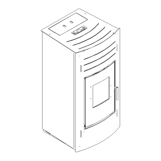
02. PRODUCT DESCRIPTION The Hydro curved front 20/24 kW and the Hydro straight front 20/24 kW stoves They are tireless workers, we simply have to remember to feed them. Available in four power versions 20/24 kW. The essential lines and curved front means it is a stove that can be used as a furnishing item. The aspects of robustness, reliability, ease of use, the cast iron and steel interiors, the corten steel exchanger and the high yields result in a self-sufficient and durable appliance. - Page 11 02. PRODUCT DESCRIPTION HYDRO KANTINA 20/24 KW STOVE TECHNICAL DATA Technical data of the appliance: CURVED FRONT HYDRO CURVED FRONT HYDRO HYDRO KANTINA 20 KW HYDRO KANTINA 24 Dati tecnici dell’apparecchio: 20 KW / STRAIGHT 24 KW / STRAIGHT FRONTHYDRO 20 KW FRONTHYDRO 24 KW Nominal heat Reduced...
-
Page 12: Description Of Components
02 PRODUCT DESCRIPTION 02.1 DESCRIPTION OF COMPONENTS 1 - Electronic pump 2 - Pressure transducer 3 - Safety valve (3bar) 4 - Heating inlet 5 - Heating return 6 - Expansion tank 7 - Fume motor 8 - Depressor 9 - Manual reset thermostat 10 - Automatic release valve... -
Page 13: Installing The Product
INSTALLATION WITH WALL FUME OUTLET IS PROHIBITED. INSTEAD THE FUME OUTLET MUST BE ROOF-TYPE AS PROVIDED FOR BY NATIONAL REGULATIONS. Eva Stampaggi S.r.l. declines any liability for any damage to persons or property arising from the failure to comply with the points mentioned above and from non-compliant product installation. - Page 14 03 PRODUCT INSTALLATION The vent pipe is one of the key features for guaranteeing the proper functioning of the stove. Thanks to the quality of the materials, the strength, the durability, the easy cleaning and maintenance, the best vent pipes are made of steel, either stainless steel or aluminised.
- Page 15 03. INSTALLING THE PRODUCT EXISTING VENT PIPE (TRADITIONAL) Types of vent pipe Examples of vent pipe Steel vent pipe with Traditional clay vent pipe double chamber with cavities. Optimal insulated with material efficiency. resistant 400°C. Optimum efficiency. Refractory vent pipe with Avoid vent pipes with insulated double chamber internal...
-
Page 16: Chimney Cowl
03. INSTALLING THE PRODUCT 03.3 CHIMNEY COWL A properly installed chimney cowl ensures optimum stove functioning. The anti-downdraught chimney cowl consists of a number of components whose outlet section sum always doubles the vent pipe section. Make sure the chimney cowl is at least 150cm above the roof top so that it is fully exposed to the wind. -
Page 17: Draught
03. INSTALLING THE PRODUCT 03.4 DRAUGHT Fumes heat up during combustion, increasing their volume. Their density is therefore lower than the one of the surrounding colder air. This difference between the inside and outside temperatures of the chimney results in a negative pressure which increases proportionally to the vent pipe length and the temperature. -
Page 18: Stove Efficiency
03. INSTALLING THE PRODUCT 03.5 STOVE EFFICIENCY Highly efficient stoves may pose difficulties for fume extraction. In order for a vent pipe to work properly its internal temperature must increase as a consequence of the fumes generated during combustion. Importantly, the efficiency of a heater is determined by its ability to transfer most of the heat produced to the environment to be heated: consequently, the greater the efficiency of the stove, the "colder"... -
Page 19: Installation
03. INSTALLING THE PRODUCT 03.6 INSTALLATION Using coaxial tubes the air will be pre-warmed contributing to improved combustion and lower emissions into the atmosphere. Follow the instructions before installing your stove. Select the position where the stove is to be installed and: ... - Page 20 03. INSTALLING THE PRODUCT The combustion air intake must be connected directly to the outside or to adjacent rooms provided they are fitted with external air supply vents and are not used as bedrooms or bathrooms or, whenever a fire hazard exists, as storage rooms, garages, combustible material warehouses, etc.
- Page 21 03. INSTALLING THE PRODUCT INSTALLATION EXAMPLE: EXAMPLE OF INCORRECT INSTALLATION: Exhaust pipes must never be fitted pointing downwards or horizontally so that fumes are discharged directly through the external wall.
- Page 22 03. INSTALLING THE PRODUCT CONNECTION EXAMPLES, SYSTEM DRAWINGS...
- Page 23 03. INSTALLING THE PRODUCT...
- Page 24 03. INSTALLING THE PRODUCT INSTALLATION In compliance with the current regulations for installation, the pellet thermo-stove should be installed in a ventilated place with air that is sufficient to ensure correct combustion and therefore good operation. The room must have a volumetry of no less than 20 m3 and to ensure good combustion (40 m3/h of air), there must be a combustion air intake"...
-
Page 25: Product Use
04. PRODUCT USE 04.1 ELECTRONICS WITH 6-BUTTON LCD DISPLAY Proper functioning and control adjustment devices Control panel The control panel shows the information concerning the stove status. Several types of data can be displayed and the settings available according to the access level can be modified by entering the menu. Depending on the selected mode and on their position on the display, the data visualised may acquire different meanings. - Page 26 04. PRODUCT USE Description of Panel BUTTON 1 (P1) - Temperature increase: When in programming mode, use this button to modify/increase the selected menu value. When in working mode/switched off, use instead this button to increase the stove temperature value. BUTTON 2 (P2) - Temperature decrease: When in programming mode, use this button to modify/decrease the selected menu value.
- Page 27 04. PRODUCT USE Level 1 Level 2 Level 3 Level 4 Value 01 - time clock setting 01 - day Week day 02 - hours Hour 03 - minutes Minute 04 - day day month 05 - month Month 06 - year Year 02 –...
- Page 28 04. PRODUCT USE Level 1 Level 2 Level 3 Level 4 Value 29 - start prog 4 Hour 30 - stop prog 4 Hour 31 - Monday prog 4 On/off 32 - Tuesday prog 4 On/off 33 - Wednesday prog 4 On/off 34 - Thursday prog 4 On/off...
- Page 29 04. PRODUCT USE Menu 01 - time clock setting Use this function to set current time and date. The control board is equipped with a lithium battery guaranteeing the internal time clock a 3/5 year-long life. Menu 02 – chrono setting Sub-menu 02 - 01 –...
- Page 30 04. PRODUCT USE Sub-menu 02 - 03 – weekly programme The weekly programmable thermostat functions can be enabled, disabled and set. The weekly programmer consists of 4 independent programmes which can be combined together in different ways. The weekly programmer can be enabled or disabled. Moreover, if the time is set to OFF, the time clock ignores the corresponding control.
- Page 31 04. PRODUCT USE PROGRAMME 4 menu level setting meaning available values 03-03-29 START PROG 4 switching-on time time - OFF 03-03-30 STOP PROG 4 switching-off time time - OFF 03-03-31 MONDAY PROG 4 on/off 03-03-32 TUESDAY PROG 4 on/off 03-03-33 WEDNESDAY PROG 4 on/off 03-03-34...
- Page 32 04. PRODUCT USE Menu 04 - stand-by-mode - activate mode 2 If you select the “STAND-BY” mode, the stove switches off after a period of time, set by Pr44, during which the room temperature remains at a value higher than the SET temperature. Only if the following condition occurs it is then possible to switch the stove back on: TSET <...
- Page 33 04. PRODUCT USE Menu 07 – stove status This function displays the current status of all the devices connected to the stove. A few examples are included in the following pages.
- Page 34 04. PRODUCT USE User functions Standard functioning of a control board properly installed on a forced air pellet stove is described below with reference to the functions available to users. The indications listed below refer to a control board fitted with programmable thermostat. Before switching on the stove, the display is as in figure 16.
- Page 35 04. PRODUCT USE Changing set stove temperature Press P1 button to change the set room temperature. The display shows the current SET temperature value. External thermostat/chronothermostat use If you want to use an external programmable thermostat, connect it to the TERM clamps (connector CN7 pin 7-8). ...
- Page 36 04. PRODUCT USE Stove switched off The display will show the wording OFF. The fume fan stops working. Stove re-ignition It will be possible to switch the stove back on only at the end of the safety period of time set by Pr38 and if the fume temperature has reached a value below Pr13.
- Page 37 04. PRODUCT USE Alarms In case of malfunctioning the control board reports the problem and activates various procedures depending on the type of alarm. Possible alarm messages are listed below. Cause Display shows Fume temperature sensor ALARM FUME SENSOR Fume overheating ALARM HOT TEMP Ignition failure ALARM NO FIRE...
- Page 38 04. PRODUCT USE Stove switching-off during working mode alarm If during normal working mode, the flame goes out and the fume temperature falls below the minimum threshold (Pr13 parameter), the alarm is activated as shown in figure 30. The stove switching-off phase starts immediately. fig.
- Page 39 04. PRODUCT USE Connections...
-
Page 40: Cleaning And Maintenance
05. CLEANING AND MAINTENANCE 05.1 INTRODUCTION The stove requires a simple yet constant cleaning to guarantee top efficiency and proper functioning. Constant maintenance by a qualified technician is recommended. The stove should be cleaned before the cold season because it can sometimes get clogged during the summer (by nests for example) preventing exhaust fumes to flow regularly. -
Page 41: Troubleshooting
06. TROUBLESHOOTING PROBLEM CAUSE SOLUTION IT MAY BE NECESSARY TO REPEAT THE FIRST LOAD PHASE A FEW TIMES TO FACILITATE THE APPLIANCE FIRST START-UP FIRST START-UP SINCE THE AUGER TUBE IS COMPLETELY EMPTY AND IT MAY TAKE A SPECIFIC PERIOD OF TIME TO FILL. POWER OUTAGE CHECK PLUG AND POWER SUPPLY. - Page 42 14. CERTIFICATE OF INSTALLATION AND TESTING LET STOVE COOL DOWN, LET STOVE COOL DOWN, MANUALLY RESET THERMOSTAT ON BACK. IF THE MANUALLY RESET PROBLEM REMAINS UNSOLVED, CONTACT A SPECIALISED TECHNICIAN. THERMOSTAT ON BACK. LET STOVE COOL DOWN, MANUALLY RESET THERMOSTAT ON BACK. SWITCH TEMPORARY POWER OUTAGE ALARM SIC FIREBOX STOVE ON AGAIN.
-
Page 43: Certificate Of Installation And Testing
07. CERTIFICATE OF INSTALLATION AND TESTING CERTIFICATE OF INSTALLATION AND TESTING CUSTOMER:___________________________ Retailer's Stamp: ROAD: _______________________________ CITY: ________________________________ Installer's stamp: POSTAL CODE: _________________________ PROVINCE: __________________________ First name: ___________________________ TEL: _________________________________ Last Name: ___________________________ Address: ___________________Postal code: Delivery date:________________________ Location: ___________________________ Delivery date: ________________________ Tel: Equipment mod.: _____________________... -
Page 45: Yearly Scheduled Maintenance
08. YEARLY SCHEDULED MAINTENANCE Date 1st maintenance ____________ / ____________ / (Technical Assistance Centre stamp) Date 2nd maintenance ____________ / ____________ / (Technical Assistance Centre stamp) Date 3rd maintenance ____________ / ____________ / (Technical Assistance Centre stamp) -
Page 46: Warranty Certificate
09. WARRANTY CERTIFICATE Congratulations! Thank you for purchasing an Eva Stampaggi product. Warranty The warranty period is two years if fiscally described as sold to an individual (Legislative Decree no. 24 of 02.02.2002) and one year if sold to a company or profession (subject to VAT). - Page 47 Attention: after purchase, please keep this warranty certificate together with the original package, installation and testing certificate and the retailer receipt. Eva Stampaggi S.r.l. Retailer Stamp and Signature Via Cal Longa Z.I.
Need help?
Do you have a question about the HYDRO CURVED FRONT 20 KW and is the answer not in the manual?
Questions and answers